FANUC Series 0i-MODEL F. For Lathe System OPERATOR'S MANUAL (B-64604EN-1/01) - page 18
 

  Index      Manuals     FANUC Series 0i-MODEL F. For Lathe System OPERATOR'S MANUAL (B-64604EN-1/01)


Search            copyright infringement  


Content      ..     16      17      18      19     ..


FANUC Series 0i-MODEL F. For Lathe System OPERATOR'S MANUAL (B-64604EN-1/01) - page 18


 B-64604EN-1/01

 PROGRAMMING 


- 265 - 

6.MEMORY OPERATION 

USING Series 10/11 FORMAT

 Unit 

Diameter/radius 

programming 

Sign 

Decimal point 

input 

Δ

Depends on the increment 
system for the reference axis. 

Radius programming 

Required 

Allowed 

Δ

Depends on the increment 
system for the reference axis. 

Radius programming 

Required 

Allowed 

Δ

Depends on the increment 
system for the reference axis. 

Depends on diameter/radius programming 
for the second axis on the plane. 

Required Allowed 

Δ

Depends on the increment 
system for the reference axis. 

Depends on diameter/radius programming 
for the first axis on the plane. 

Required


Allowed 


Δ

k+

Δ

w


Δ

w


A'


Δ

u/2


Δ

i+

Δ

u/2


B

D

C


Δ

w


Δ

u/2

Target figure 

(F):  Cutting feed 
(R):  Rapid traverse 

(R)

+X


+Z


(R)

A

(F)


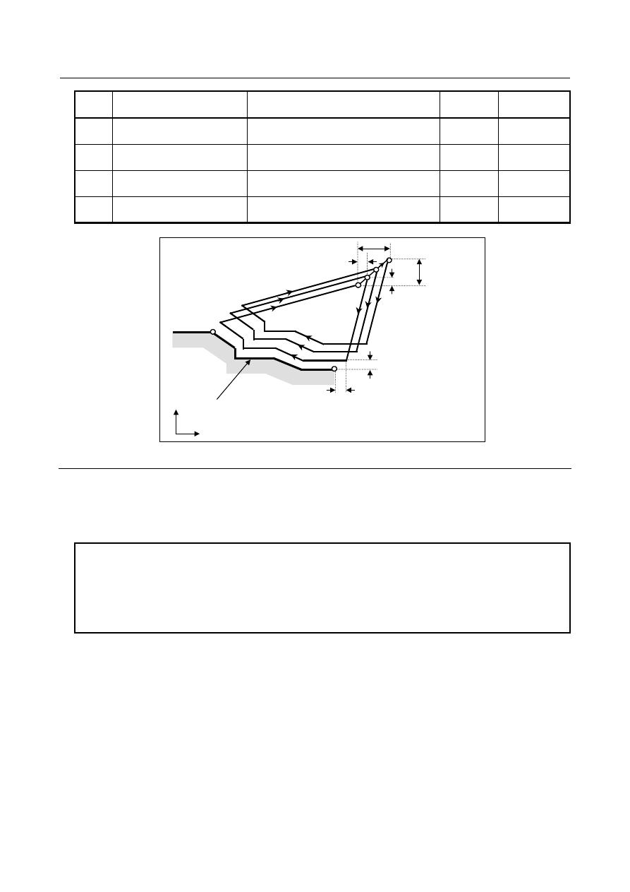
Fig. 6.4.3 (c) Cutting path in pattern repeating 


Explanation 

 -  Operations 

When a target figure passing through A, A', and B in this order is given by a program, rough cutting is 
performed the specified number of times, with the finishing allowance specified by 

Δ

u/2 and 

Δ

w left. 


NOTE 

1  After cycle operation terminates, the tool returns to point A. 
2  F, S, and T functions which are specified in the move command between points 

A and B are ineffective and those specified in G73 block or the previous block 
are effective. M and second auxiliary functions are treated in the same way as F, 
S, and T functions. 


Target figure 

 Patterns 

As in the case of G71, there are four target figure patterns. Be careful about signs of 

Δ

u, 

Δ

w, 

Δ

i, and 

Δ

when programming this cycle. 


Start block 

In the start block in the program for the target figure (block with sequence number ns in which the path 
between A and A' is specified), G00 or G01 must be specified. If it is not specified, alarm PS0065 is 
issued. 
When G00 is specified, positioning is performed along A-A’. When G01 is specified, linear interpolation 
is performed with cutting feed along A-A’. 
 

 PROGRAMMING 

 B-64604EN-1/01


- 266 - 

6. MEMORY OPERATION   

USING Series 10/11 FORMAT 


Check function 

The following check can be made. 
 

Check Related 

parameter 

Checks that a block with the sequence number specified at address 
Q is contained in the program before cycle operation. 

Enabled when bit 2 (QSR) of parameter 
No. 5102 is set to 1. 


  - 

Tool nose radius compensation 

Like G71, this cycle operation is performed according to the figure determined by the tool nose radius 
compensation path when the offset vector is 0 at start point A and start-up is performed in a block 
between path A-A'. 

 B-64604EN-1/01

 PROGRAMMING 


- 267 - 

6.MEMORY OPERATION 

USING Series 10/11 FORMAT

6.4.4 

Finishing Cycle (G70) 

After rough cutting by G71, G72 or G73, the following command permits finishing. 
 

Format 

G70 P(ns) Q(nf) ; 

ns : Sequence number of the first block for the program of finishing shape. 
nf  : Sequence number of the last block for the program of finishing shape. 


Explanation 

 -  Operations 

The blocks with sequence numbers ns to nf in the program for a target figure are executed for finishing. 
The F, S, T, M, and second auxiliary functions specified in the G71, G72, or G73 block are ignored and 
the F, S, T, M, and second auxiliary functions specified in the blocks with sequence numbers ns to nf are 
effective. 
When cycle operation terminates, the tool is returned to the start point in rapid traverse and the next G70 
cycle block is read. 
 

 -  Target figure 
 Check 

function 

The following check can be made. 
 

Check Related 

parameter 

Checks that a block with the sequence number specified at address 
Q is contained in the program before cycle operation. 

Enabled when bit 2 (QSR) of parameter 
No. 5102 is set to 1. 


  - 

Storing P and Q blocks 

When rough cutting is executed by G71, G72, or G73, up to three memory addresses of P and Q blocks 
are stored. By this, the blocks indicated by P and Q are immediately found at execution of G70 without 
searching memory from the beginning for them. After some G71, G72, and G73 rough cutting cycles are 
executed, finishing cycles can be performed by G70 at a time. At this time, for the fourth and subsequent 
rough cutting cycles, the cycle time is longer because memory is searched for P and Q blocks. 
 

Example 


G71 P100 Q200 ...; 

 N100 

...; 

 ...; 
 ...; 
 N200 

...; 


G71 P300 Q400 ...; 

 N300 

...; 

 ...; 
 ...; 
 N400 

...; 

 ...; 
 ...; 
 

G70 P100 Q200 ;  (Executed without a search for the first to third cycles) 


G70 P300 Q400 ;  (Executed after a search for the fourth and subsequent 

cycles) 


 PROGRAMMING 

 B-64604EN-1/01


- 268 - 

6. MEMORY OPERATION   

USING Series 10/11 FORMAT 

NOTE 


The memory addresses of P and Q blocks stored during rough cutting cycles by 
G71, G72, and G73 are erased after execution of G70. 


All stored memory addresses of P and Q blocks are also erased by a reset. 


  - 

Return to the cycle start point 

In a finishing cycle, after the tool cuts the workpiece to the end point of the target figure, it returns to the 
cycle start point in rapid traverse. 
 

NOTE 


The tool returns to the cycle start point always in the nonlinear positioning mode 
regardless of the setting of bit 1 (LRP) of parameter No. 1401. 


Before executing a finishing cycle for a target figure with a pocket cut by G71 or 
G72, check that the tool does not interfere with the workpiece when returning 
from the end point of the target figure to the cycle start point. 


  - 

Tool nose radius compensation 

When using tool nose radius compensation, specify a tool nose radius compensation command (G41 or 
G42) before a multiple repetitive canned cycle command (G70) and specify the cancel command (G40) 
after the multiple repetitive canned cycle command (G70). 
 
Program example 
G42;..............................Specify this command before a multiple repetitive canned cycle command. 
G70P10Q20; 
G40;..............................Specify this command after a multiple repetitive canned cycle command. 
 
Like G71, this cycle operation is performed according to the figure determined by the tool nose radius 
compensation path when the offset vector is 0 at start point A and start-up is performed in a block 
between path A-A'. 
 

 B-64604EN-1/01

 PROGRAMMING 


- 269 - 

6.MEMORY OPERATION 

USING Series 10/11 FORMAT

Example 


Stock removal in facing (G72)


(Diameter designation for X axis, metric input)


N011 

G50 X220.0 Z190.0 ; 

N012 

G00 X176.0 Z132.0 ; 

N013 

G72 P014 Q019 U4.0 W2.0 D7000 F0.3 S550 ; 

N014 

G00 Z56.0 S700 ; 

N015     G01 X120.0 W14.0 F0.15 ; 
N016 W10.0 

N017 X80.0 

W10.0 

N018 W20.0 

N019 X36.0 

W22.0 

N020 

G70 P014 Q019 ; 

 
Parameter No. 5133 = 1.0 (escaping amount) 
Finishing allowance (4.0 in diameter in the X direction, 2.0 in the Z direction) 


φ

120


φ

80


φ

40

φ

160 


20

2


88 

Start point


Z axis

X axis


20

10 


60

 10 


10

190

1

10 

7

2

2


 PROGRAMMING 

 B-64604EN-1/01


- 270 - 

6. MEMORY OPERATION   

USING Series 10/11 FORMAT 

Pattern repeating (G73)


(Diameter designation, metric input)


φ

80


φ

180


Z axis

X axis


220

  B

2


130


 16


 16

1

10 

14


φ

160


2

14

0


20

φ

120


40


10


40

20

40

10

N011 

G50 X260.0 Z220.0 ; 

N012 

G00 X220.0 Z160.0 ; 

N013 

G73 P014 Q019 U4.0 W2.0 I14.0 K14.0 D3 F0.3 S0180


N014 

G00 X80.0 W-40.0 ; 

N015 

G01 W-20.0 F0.15 S0600 ; 

N016 X120.0 

W-10.0; 

N017 

W-20.0 S0400 ; 

N018 

G02 X160.0 W-20.0 R20.0 ; 

N019 

G01 X180.0 W-10.0 S0280 ; 

N020 

G70 P014 Q019 ; 


 B-64604EN-1/01

 PROGRAMMING 


- 271 - 

6.MEMORY OPERATION 

USING Series 10/11 FORMAT

6.4.5 

End Face Peck Drilling Cycle (G74) 

This cycle enables chip breaking in outer diameter cutting. If the second axis on the plane (X-axis 
(U-axis) for the ZX plane) and address P are omitted, operation is performed only along the first axis on 
the plane (Z-axis for the ZX plane), that is, a peck drilling cycle is performed. 


Format 

ZpXp-plane 

G74X(U)_ Z(W)_ I(

Δ

i) K(

Δ

k) D(

Δ

d) F(f ) ; 

YpZp-plane 

G74Y(V)_ Z(W)_ J(

Δ

k) K(

Δ

i) D(

Δ

d) F(f ) ; 

XpYp-plane 

G74X(U)_ Y(V)_ I(

Δ

k) J(

Δ

i) D(

Δ

d) F(f ) ; 

X_,Z_  : Coordinate of the second axis on the plane (X-axis for the ZX plane) at point B 

and 


  Coordinate of the first axis on the plane (Z-axis for the ZX plane) at point C 

U_,W_ : Travel distance along the second axis on the plane (U for the ZX plane) from 

point A to B 


  Travel distance along the first axis on the plane (W for the ZX plane) from point 

A to C 
(When G code system A is used. In other cases, X_, Z_ is used for 
specification.) 

Δ

: Travel distance in the direction of the second axis on the plane (X-axis for the 

ZX plane) 

Δ

: Depth of cut in the direction of the first axis on the plane (Z-axis for the ZX 

plane) 

Δ

: Relief amount of the tool at the cutting bottom 

f : 

Feedrate 


 Unit 

Diameter/radius 

programming 

Sign 

Decimal point 

input 

Δ

Depends on the increment system for 
the reference axis. 

Radius programming 

Not required 

Allowed 

Δ

Depends on the increment system for 
the reference axis. 

Radius programming 

Not required 

Allowed 

Δ

Depends on the increment system for 
the reference axis. 

Radius programming 

NOTE 1 

Not allowed 


NOTE 

1  Normally, specify a positive value for 

Δ

d. When X (U) and 

Δ

i are omitted, specify 

a value with the sign indicating the direction in which the tool is to escape. 

2  Even if pocket calculator type decimal point programming is specified (bit 0 (DPI) 

of parameter No. 3401 = 1), the unit of address D is least input increment. In 
addition, when a decimal point is input in address D, an alarm PS0007, 
“ILLEGAL USE OF DECIMAL POINT” is issued. 


 PROGRAMMING 

 B-64604EN-1/01


- 272 - 

6. MEMORY OPERATION   

USING Series 10/11 FORMAT 


 U/2


  W

Δ

d


Δ

i’

  C


Δ

k'


Δ

k


Δ

k


Δ

k


Δ

k

  A


(R)

 (R) 


(F)


 (R)


 (R)

 (R)


(F)

 (F)

 (F) 

 (F)


Δ

i


Δ

i


  e

  B

[0 < 

Δ

k’ 


Δ

k]


  X

 Z 

 (R)

[0 < 

Δ

i’ 


Δ

i]


(R) ... Rapid traverse 
(F) ... Cutting feed


+X


+Z


e : Return amount (parameter No.5139) 


Fig. 6.4.5 (a) Cutting path in end face peek drilling cycle 


Explanation 

 -  Operations 

A cycle operation of cutting by 

Δ

k and return by e is repeated. 

When cutting reaches point C, the tool escapes by 

Δ

d. Then, the tool returns in rapid traverse, moves to 

the direction of point B by 

Δ

i, and performs cutting again. 


  - 

Return amount (e) 

The return amount (e) is set in parameter No. 5139. 
 

No. Unit 

Diameter/radius 

programming 

Sign 

5139 

Depends on the increment system for the 
reference axis. 

Radius programming 

Not required 


  - 

Tool nose radius compensation 

Tool nose radius compensation cannot be applied. 
 

 B-64604EN-1/01

 PROGRAMMING 


- 273 - 

6.MEMORY OPERATION 

USING Series 10/11 FORMAT

6.4.6 

Outer Diameter / Internal Diameter Drilling Cycle (G75) 

This cycle is equivalent to G74 except that the second axis on the plane (X-axis for the ZX plane) 
changes places with the first axis on the plane (Z-axis for the ZX plane). This cycle enables chip breaking 
in end facing. It also enables grooving during outer diameter cutting and cutting off (when the Z-axis 
(W-axis) and Q are omitted for the first axis on the plane). 
 

Format 

ZpXp-plane 

G75 X(U)_ Z(W)_ I(

Δ

i) K(

Δ

k) D(

Δ

d) F (f ) ; 

YpZp-plane 

G75 Y(V)_ Z(W)_ J(

Δ

k) K(

Δ

i) D(

Δ

d) F(f ) ; 

XpYp-plane 

G75 X(U)_ Y(V)_ I(

Δ

k) J(

Δ

i) D(

Δ

d) F(f ) ; 

X_, Z_  :  Coordinate of the second axis on the plane (X-axis for the ZX plane) at point B 

and 


  Coordinate of the first axis on the plane (Z-axis for the ZX plane) at point C 

U_, W_  :  Travel distance along the second axis on the plane (U for the ZX plane) from 

point A to B 


  Travel distance along the first axis on the plane (W for the ZX plane) from point 

A to C 

Δ

:  Depth of cut in the direction of the second axis on the plane (X-axis for the ZX 

plane) 

Δ

:  Travel distance in the direction of the first axis on the plane (Z-axis for the ZX 

plane) 

Δ

:  Relief amount of the tool at the cutting bottom 

f : 

Feedrate 


 Unit 

Diameter/radius 

programming 

Sign 

Decimal point 

input 

Δ

Depends on the increment system for 
the reference axis. 

Radius programming 

Not required 

Allowed 

Δ

Depends on the increment system for 
the reference axis. 

Radius programming 

Not required 

Allowed 

Δ

Depends on the increment system for 
the reference axis. 

Radius programming 

NOTE 1 

Not allowed 


NOTE 

1  Normally, specify a positive value for 

Δ

d. When Z (W) and 

Δ

k are omitted, 

specify a value with the sign indicating the direction in which the tool is to 
escape. 

2  Even if pocket calculator type decimal point programming is specified (bit 0 (DPI) 

of parameter No. 3401 = 1), the unit of address D is least input increment. In 
addition, when a decimal point is input in address D, an alarm PS0007, 
“ILLEGAL USE OF DECIMAL POINT” is issued. 


 PROGRAMMING 

 B-64604EN-1/01


- 274 - 

6. MEMORY OPERATION   

USING Series 10/11 FORMAT 


W


Δ

d

A

 (R)


(F)


Δ

i

  e

Z


Δ

k

  X


(F)

 (F)

(R)

(F)

(R)

(R)

 (F)

 (R)


U/2 

(R) ... Rapid traverse 
(F) ... Cutting feed


(R)

B


Δ

i


Δ

i


Δ

i

+X


+Z


Δ

i’

e : Return amount (parameter No.5139) 


Fig. 6.4.6 (a) Outer diameter/internal diameter drilling cycle   


Explanation 

 -  Operations 

A cycle operation of cutting by 

Δ

i and return by e is repeated. 

When cutting reaches point B, the tool escapes by 

Δ

d. Then, the tool returns in rapid traverse, moves to 

the direction of point C by 

Δ

k, and performs cutting again. 

 
Both G74 and G75 are used for grooving and drilling, and permit the tool to relief automatically. Four 
symmetrical patterns are considered, respectively. 
 

  - 

Return amount (e) 

The return amount (e) is set in parameter No. 5133. 
 

No. Unit 

Diameter/radius 

programming 

Sign 

5139 

Depends on the increment system for the 
reference axis. 

Radius programming 

Not required 


  - 

Tool nose radius compensation 

Tool nose radius compensation cannot be applied. 
 

 B-64604EN-1/01

 PROGRAMMING 


- 275 - 

6.MEMORY OPERATION 

USING Series 10/11 FORMAT

6.4.7 

Multiple Threading Cycle (G76) 

The multiple threading cycle can select four cutting methods. 
 

Format 

ZpXp-plane 

G76 X(U)_ Z(W)_ I(i) K(k) D(

Δ

d) A(a) F(L) P(p) Q(q) ; 

YpZp-plane 

G76 Y(V)_ Z(W)_ J(k) K(i) D(

Δ

d) A(a) F(L) P(p) Q(q) ; 

XpYp-plane 

G76 X(U)_ Y(V)_ I(k) J(i) D(

Δ

d) A(a) F(L) P(p) Q(q) ; 

X_, Z_  : Coordinates of the cutting end point (point D in the figure) in the direction of the 

length 

U_, W_  : Travel distance to the cutting end point (point D in the figure) in the direction of the 

length 

: Angle of tool nose 


  From 0 to 120 in steps of 1 degree (The default is 0.) 

i : 

Taper 

amount 


  If i = 0, ordinary straight threading can be made. 

: Height of thread 

Δ

: Depth of cut in 1st cut   

: Lead of thread 

: Cutting method (one-edge threading with constant cutting amount by default or for 

P0) 
P1 :  One-edge threading with constant cutting amount 
P2 :  Both-edge zigzag threading with constant cutting amount 
P3 :  One-edge threading with constant depth of cut 
P4 :  Both-edge zigzag threading with constant depth of cut 

: Threading start angle shift (From 0 to 360 degrees in steps of 0.001 degrees) 


NOTE 

1  Even if pocket calculator type decimal point programming is specified (bit 0 (DPI) 

of parameter No. 3401 = 1), the unit of address D is least input increment. In 
addition, when a decimal point is input in address D, an alarm PS0007, 
“ILLEGAL USE OF DECIMAL POINT” is issued. 

2  A decimal point included in address A has no meaning. That is, ‘A120.’ is 

equivalent to ‘A120’ in specifying 120 degrees. 

3  Address Q does not allow decimal point input. 


 Unit 

Diameter/radius 

programming 

Sign 

Decimal point 

input 

Depends on the increment system for 
the reference axis. 

Radius programming 

Required 

Allowed 

Depends on the increment system for 
the reference axis. 

Radius programming 

Not required 

Allowed 

Δ

Depends on the increment system for 
the reference axis. 

Radius programming 

Not required 

Not allowed 


 PROGRAMMING 

 B-64604EN-1/01


- 276 - 

6. MEMORY OPERATION   

USING Series 10/11 FORMAT 


  W

 (F)

 (R)

 A 

 U/2


Δ

d


  i


Z

  r


k


 (R)


+X 

+Z 

 (R)


  r:    Amount of thread chamfering (parameter No.5130) 


Fig. 6.4.7 (a) Cutting path in multiple threading cycle 


Explanation 

 -  Operations 

This cycle performs threading so that the length of the lead only between C and D is made as specified in 
the F code. In other sections, the tool moves in rapid traverse. 
The time constant for acceleration/deceleration after interpolation and FL feedrate for thread chamfering 
and the feedrate for retraction after chamfering are the same as for thread chamfering with canned cycle. 
 

 CAUTION 


Notes on threading are the same as those on G32 threading. For feed hold in a 
threading cycle, however, see "Feed hold in a threading cycle" described below. 

 
 -  Cutting method 

There are four cutting methods. 


Tool tip


  k

Δ

d


1st 

 3rd 

2nd 

nth

a

One-edge thread cutting with constant cutting amount(P1)

d (finishing allowance) 

4th 


Δ

d

n


a

Tool tip


Both-edge zigzag thread cutting with constant cutting amount(P2)

d (finishing allowance) 

2

⋅Δ

d / 2

1st 

2nd 

3rd 

5th 

6th 


Fig. 6.4.7 (b) One-edge threading with constant cutting amount,   

both-edge zigzag threading with constant cutting amount (P1/2) 


 B-64604EN-1/01

 PROGRAMMING 


- 277 - 

6.MEMORY OPERATION 

USING Series 10/11 FORMAT


Δ

d

k

d (finishing allowance)

Δ

d

Δ

d

Δ

d

Δ

d

One-edge thread cutting with constant depth of cut (P3) 

d (finishing allowance) 

a

Δ

Δ

Δ

Δ

Both-edge zigzag thread cutting with constant depth of cut (P4)

Tool tip

Tool tip


Fig. 6.4.7 (c) One-edge threading with constant depth of cut,   

both-edge zigzag threading with constant depth of cut (P3/4) 


  - 

Repetitive count in finishing 

The last finishing cycle (cycle in which the finishing allowance is removed by cutting) is repeated. 
The repetitive count is set in parameter No. 5142. 
If the setting is 0, the operation is performed once. 

+X

+Z

k

d (finishing allowance)

Last finishing cycle


  - 

Minimum depth of cut 

When a cutting method with constant cutting amount is selected (P1 or P2), clamping can be performed 
with the minimum depth of cut to prevent the depth of cut from becoming too small. 
The minimum depth of cut is set in parameter No. 5140. 
 

No. Unit 

Diameter/radius 

programming 

Sign 

5140 

Depends on the increment system for the 
reference axis. 

Radius programming 

Not required 


 -  Finishing allowance 

The finishing allowance is set in parameter No. 5141. 
 

No. Unit 

Diameter/radius 

programming 

Sign 

5141 

Depends on the increment system for the 
reference axis. 

Radius programming 

Not required 


NOTE 


Set a value smaller than the height of thread as the finishing allowance. (No. 
5141 < k) 


 PROGRAMMING 

 B-64604EN-1/01


- 278 - 

6. MEMORY OPERATION   

USING Series 10/11 FORMAT 

  - 

Relationship between the sign of the taper amount and tool path 

The signs of incremental dimensions for the cycle shown in Fig. 6.4.7 (a) are as follows: 
Cutting end point in the direction of the length for U and W:   
 

  Minus (determined according to the directions of paths A-C and C-D) 

Taper amount (i) 

:  Minus (determined according to the direction of path A-C) 

Height of thread (k) 

:  Plus (always specified with a plus sign) 

Depth of cut in the first cut (

Δ

d)  :  Plus (always specified with a plus sign) 

The four patterns shown in the Table 6.4.7 (a) are considered corresponding to the sign of each address. A 
female thread can also be machined. 
 

Table 6.4.7 (a) 

Outer diameter machining 

Internal diameter machining 

1. U < 0, W < 0, i < 0 

2. U > 0, W < 0, i > 0 

Z


U/2


3(R)


4(R)


1(R)

2(F)


W


i

X


X

Z

U/2

3(R)

4(R)


1(R)

2(F)


W


i

X


3. U < 0, W < 0, i > 0 

at |i|

|U/2| 

4. U > 0, W < 0, i < 0 

at |i|

|U/2| 


Z


U/2 

3(R) 

4(R)


1(R)

2(F)


W


i


X

Z

U/2

3(R)

4(R)


1(R)

2(F)


W


i

X


 -  Acceleration/deceleration after interpolation for threading 

Acceleration/deceleration after interpolation for threading is acceleration/deceleration of exponential 
interpolation type. By setting bit 5 (THLx) of parameter No. 1610, the same acceleration/deceleration as 
for cutting feed can be selected. (The settings of bits 1 (CTBx) and 0 (CTLx) of parameter No. 1610 are 
followed.) However, as a time constant and FL feedrate, the settings of parameter No. 1626 and No. 1627 
for the threading cycle are used. 
 

  - 

Time constant and FL feedrate for threading 

The time constant for acceleration/deceleration after interpolation for threading specified in parameter No. 
1626 and the FL feedrate specified in parameter No. 1627 are used. 
The FL feedrate is valid only for exponential acceleration/deceleration after interpolation.


 -  Thread chamfering 

Thread chamfering can be performed in this threading cycle. A signal from the machine tool initiates 
thread chamfering. 
The maximum amount of thread chamfering (r) can be specified in a range from 0.1L to 12.7L in 0.1L 
increments in parameter No. 5130. 

 B-64604EN-1/01

 PROGRAMMING 


- 279 - 

6.MEMORY OPERATION 

USING Series 10/11 FORMAT

A thread chamfering angle between 1 to 89 degrees can be specified in parameter No. 5131. When a 
value of 0 is specified in the parameter, an angle of 45 degrees is assumed. 
For thread chamfering, the same type of acceleration/deceleration after interpolation, time constant for 
acceleration/deceleration after interpolation, and FL feedrate as for threading are used. 
 

NOTE 


Common parameters for specifying the amount and angle of thread chamfering 
are used for this cycle and G92 threading cycle. 


  - 

Retraction after chamfering 

The Table 6.4.7 (b) lists the feedrate, type of acceleration/deceleration after interpolation, and time 
constant of retraction after chamfering. 
 

Table 6.4.7 (b) 

Bit 3 (CFR) of 

parameter No. 1611 

Parameter No. 

1466 

Description 

Other than 0 

Uses the type of acceleration/deceleration after interpolation for threading, 
time constant for threading (parameter No. 1626), FL feedrate (parameter 
No. 1627), and retraction feedrate specified in parameter No. 1466. 

Uses the type of acceleration/deceleration after interpolation for threading, 
time constant for threading (parameter No. 1626), FL feedrate (parameter 
No. 1627), and rapid traverse rate specified in parameter No. 1420. 


Before retraction a check is made to see that the specified feedrate has 
become 0 (delay in acceleration/deceleration is 0), and the type of 
acceleration/deceleration after interpolation for rapid traverse is used 
together with the rapid traverse time constant and the rapid traverse rate 
(parameter No. 1420). 

 
By setting bit 4 (ROC) of parameter No. 1403 to 1, rapid traverse override can be disabled for the feedrate 
of retraction after chamfering. 
 

NOTE 


During retraction, the machine does not stop with an override of 0% for the 
cutting feedrate regardless of the setting of bit 4 (RF0) of parameter No. 1401. 


  - 

Shifting the start angle 

Address Q can be used to shift the start angle of threading. 
The start angle (Q) increment is 0.001 degrees and the valid setting range is between 0 and 360 degrees. 
No decimal point can be specified. 
 

  - 

Feed hold when the threading cycle retract function is used 

When feed hold is applied during threading in a multiple threading cycle (G76), the tool quickly retracts 
in the same way as for the last chamfering in a threading cycle and returns to the start point in the current 
cycle. 
When cycle start is triggered, the multiple threading cycle resumes. 

 PROGRAMMING 

 B-64604EN-1/01


- 280 - 

6. MEMORY OPERATION   

USING Series 10/11 FORMAT 


F e e d  h o ld  is  a p plied   a t  th is   po in t

Sta rt  p o in t 
in   the   c urre n t c yc le


O rd in a ry  c yc le


R a p id   tra ve rs e

M o tio n   a t  fe ed   h old


X -a xis


Z -a xis


C u ttin g fe ed


The angle of chamfering during retraction is the same as that of chamfering at the end point. 
 

 CAUTION 


Feed hold operation during retraction is disabled. 


 -  Inch threading 

Inch threading specified with address E is allowed. 
 

  - 

Tool nose radius compensation 

Tool nose radius compensation cannot be applied. 
 

Example 


G00 X80.0 Z130.0; 
G76 X60.64 Z25.0 K3680 D1800 A60 P1 F6.0 ; 
Parameter No.5130 = 10(1.0L)


1.

8


3.

68


6

Z axis


 105

 25


ϕ

60.

64


1.

8


X axis


0


ϕ

68


Content      ..     16      17      18      19     ..