FANUC Series 0i-MODEL F. For Lathe System OPERATOR'S MANUAL (B-64604EN-1/01) - page 15
 

  Index      Manuals     FANUC Series 0i-MODEL F. For Lathe System OPERATOR'S MANUAL (B-64604EN-1/01)


Search            copyright infringement  


Content      ..     13      14      15      16     ..


FANUC Series 0i-MODEL F. For Lathe System OPERATOR'S MANUAL (B-64604EN-1/01) - page 15


 B-64604EN-1/01

 PROGRAMMING 

5.COMPENSATION FUNCTION


- 217 - 

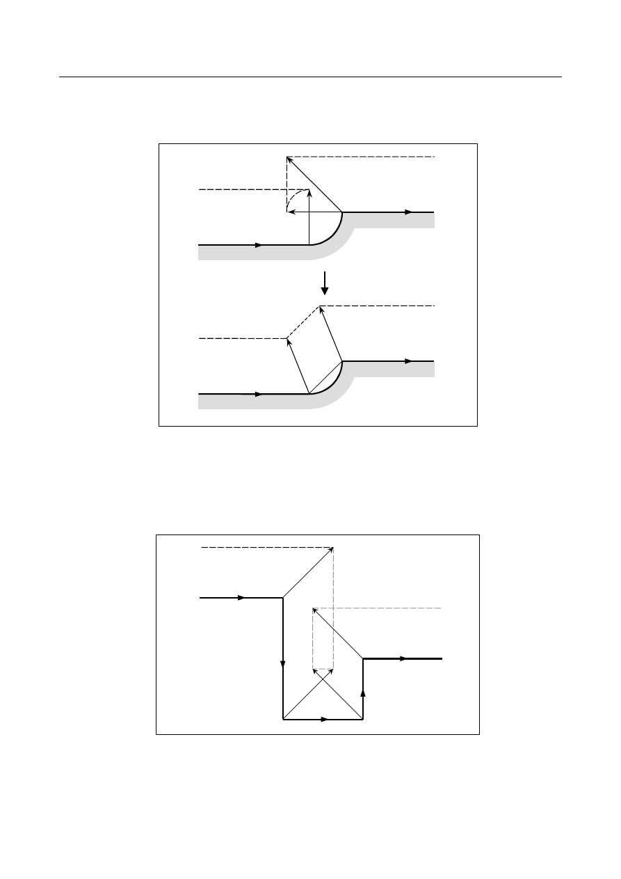
If the cutter or tool nose radius compensation value is greater than the radius of the specified arc as shown 
in the Fig. 5.4.6.3 (c), and a command is specified which results in compensation with respect to the 
inside of the arc, interference is avoided by performing intersection calculation with an arc command 
being assumed a linear one. In this case, avoided vectors are connected with linear interpolation. 

Programmed path

Post-compensation path


Fig. 5.4.6.3 (c) 


  - 

If no interference avoidance vector exists 

If the parallel pocket shown in the Fig. 5.4.6.3 (d) is to be machined, the end-point vector of block 1 and 
the end-point vector of block 2 are judged to interfere, and an attempt is made to calculate, as an 
interference avoidance vector, the intersection vector of the post-compensation path of block 1 and the 
post-compensation path of block 3. In this case, because blocks 1 and 3 are parallel to each other, no 
intersection exists. In this case, an alarm will occur immediately before block 1 and the tool will stop. 


Block 

1

Block 

2

Block 

3


Programmed path

Tool center path

Stopped


Fig. 5.4.6.3 (d) 


5.COMPENSATION FUNCTION

 PROGRAMMING 

 B-64604EN-1/01


- 218 - 

If the circular pocket shown in the Fig. 5.4.6.3 (e) is to be machined, the end-point vector of block 1 and 
the end-point vector of block 2 are judged to interfere, and an attempt is made to calculate, as an 
interference avoidance vector, the intersection vector of the post-compensation path of block 1 and the 
post-compensation path of block 3.   
In this case, because blocks 1 and 3 are circular, no post-compensation intersection exists. In this case, an 
alarm will occur immediately before block 1 and the tool will stop, as in the previous example. 

Programmed path

Tool center path

Block 

1

Block 

2

Block 

3

Stopped


Fig. 5.4.6.3 (e) 


  - 

If it is judged dangerous to avoid interference 

If the acute-angle pocket shown in the Fig. 5.4.6.3 (f) is to be machined, the end-point vector of block 1 
and the end-point vector of block 2 are judged to interfere, and an attempt is made to calculate, as an 
interference avoidance vector, the intersection vector of the post-compensation path of block 1 and the 
post-compensation path of block 3. In this case, the movement direction of the post-avoidance path 
extremely differs from the previously specified direction. If the post-avoidance path extremely differs 
from that of the original command (90

°

 or greater or 270

°

 or less), interference avoidance operation is 

judged dangerous; an alarm will occur immediately before block 1 and the tool will stop. 

Tool center path

Programmed path

Block 

1

Block 

2

Block 

3

Stopped

Post-compensation intersection of
blocks 

1

 and 

3


Fig. 5.4.6.3 (f) 


 B-64604EN-1/01

 PROGRAMMING 

5.COMPENSATION FUNCTION


- 219 - 

If a pocket in which the bottom is wider than the top, such as that shown in the Fig. 5.4.6.3 (g), is to be 
machined, the end-point vector of block 1 and the end-point vector of block 2 are judged to interfere, and 
an attempt is made to calculate, as an interference avoidance vector, the intersection vector of the 
post-compensation path of block 1 and the post-compensation path of block 3. In this case, the relation 
between blocks 1 and 3 is judged an outer one, the post-avoidance path results in overcutting as compared 
with the original command. In such a case, interference avoidance operation is judge dangerous; an alarm 
will occur immediately before block 1 and the tool will stop. 

Tool center path

Programmed path

Post-compensation intersection
of blocks 

1

 and 

3

Block 

1

Block 

2

Block 

3

Stopped


Fig. 5.4.6.3 (g) 


  - 

If further interference with an interference avoidance vector occurs 

If the pocket shown in the Fig. 5.4.6.3 (h) is to be machined, if the number of blocks to read is 3, the 
end-point vector of block 1 and the end-point vector of block 2 are judged to interfere, and an attempt is 
made to calculate, as an interference avoidance vector, the intersection vector of the post-compensation 
path of block 1 and the post-compensation path of block 3. In this case, however, the end-point vector of 
block 3 that is to be calculated next further interferes with the previous interference avoidance vector. If a 
further interference occurs to the interference avoidance vector once created and output, the movement in 
the block will not be performed; an alarm will occur immediately before the block and the tool will stop. 


Tool center path 

Programmed path 

Block 

1

Block 

2

Block 

3


Block 

5


The intersection vectors of 
blocks 

3

 and 

4

 further interfere. 

Stopped

Block 

4


Fig. 5.4.6.3 (h) 


5.COMPENSATION FUNCTION

 PROGRAMMING 

 B-64604EN-1/01


- 220 - 

NOTE 

1  For "If it is judged dangerous to avoid interference" and "If further interference 

with an interference avoidance vector occurs", by setting bit 6 (NAA) of 
parameter No. 19607 appropriately, it is possible to suppress an alarm to 
continue machining. For "If no interference avoidance vector exists", however, it 
is not possible to avoid an alarm regardless of the setting of this parameter. 

2  If a single block stop occurs during interference avoidance operation, and an 

operation is performed which differs from the original movement, such as 
manual intervention, MDI intervention, cutter or tool nose radius compensation 
value change, intersection calculation is performed with a new path. If such an 
operation is performed, therefore, an interference may occur again although 
interference avoidance has been performed once. 


5.4.7 

Cutter or Tool Nose Radius Compensation for Input from MDI 

Explanation 

 -  MDI operation 

During MDI operation, that is, if a program command is specified in MDI mode in the reset state to make 
a cycle start, intersection calculation is performed for compensation in the same way as in memory 
operation/DNC operation. Compensation is performed in the same way if a subprogram is called from 
program memory due to MDI operation. 


   Subprogram in program memory 


O9000 ; 
N1 G41 G17 G01 U10.0 V10.0 
   T0101 ; 
N2 V15.0 ; 
N3 U15.0 ; 
N4 V-15.0 ; 
N5 U-15.0 ; 
N6 G40 U-10.0 V-10.0 ; 
M99 ;


  MDI command 


G00 X0 Y0 ; 
M98 P9000 ; 
M02 ;


N6


N2

N3


N4

N5


N1


Fig. 5.4.7 (a) 


 -  MDI intervention 

If MDI intervention is performed, that is, if a single block stop is performed to enter the automatic 
operation stop state in the middle of memory operation, DNC operation, and the like, and a program 
command is specified in MDI mode to make a cycle start, cutter compensation does not perform 
intersection calculation, retaining the last compensation vector before the intervention. 

 B-64604EN-1/01

 PROGRAMMING 

5.COMPENSATION FUNCTION


- 221 - 


MDI intervention

 MDI intervention
 

W30.0 ; 
U20.0 W20.0 ; 
U-20.0 W20.0 ; 

 MEM mode 
 

  (G41) 
N2 U30.0 W10.0 ; 
N3 U-30.0 W10.0 ; 
N4 W40.0 ;


N2  N3


N4


Program command 

Last compensation vector

Retained compensation vector 


Fig. 5.4.7 (b) 


5.COMPENSATION FUNCTION

 PROGRAMMING 

 B-64604EN-1/01


- 222 - 

5.5 

VECTOR RETENTION (G38) 

In cutter or tool nose radius compensation, by specifying G38 in offset mode, it is possible to retain the 
compensation vector at the end position of the previous block, without performing intersection 
calculation. 
 

Format 

(In offset mode) 

G38 

IP

_ ; 

IP 

:Value specified for axial movement 


Explanation 

 -  Vector retention 

By specifying the above command, a vector is created at the end point of the block immediately 
preceding the G38 block, vertical to that block. In the G38 block, the vertical vector output in the 
previous block is retained. G38 is a one-shot G code. With the next move command without a G38 
command, the compensation vector is re-created. 
 

Limitation 

 -  Mode 

Specify G38 in either G00 or G01 mode. If it is specified in G02 or G03 (circular interpolation) mode, a 
radial error may occur at the start and end points. 
 

 -  Start-up/cancel 

In start-up/cancel, the operation is as described in Subsections 5.4.2 and 5.4.4. Thus, G38 cannot be 
specified in the following blocks: 
1) 

Start-up command (G41 or G42) block 

2) 

Cancel command (G40) block 

3) 

Block immediately preceding the cancel command (G40) block 


Example 

X axis

Z axis

(10.0, 0.0)

(15.0, 5.0)

Block N1

Offset vector

Block N2

Block N3

Program command

Tool nose radius
center path


:

                :

     (In offset mode)

N1 G38 X0.0 Z10.0 ;
N2 G38 X5.0 Z15.0 ;
N3 G38 X0.0 Z10.0 ;
N4          Z20.0 ;
                :
                :


Fig. 5.5 (a) 


 B-64604EN-1/01

 PROGRAMMING 

5.COMPENSATION FUNCTION


- 223 - 

5.6 

CORNER CIRCULAR INTERPOLATION (G39) 

By specifying G39 in offset mode during cutter or tool nose radius compensation, corner circular 
interpolation can be performed. The radius of the corner circular interpolation equals the compensation 
value. 
 

Format 

In offset mode 

G39 ; 

or 

I_J_ 

G39 I_K_   ; 

 J_K_ 


Explanation 

  - 

Corner circular interpolation 

When the command indicated above is specified, corner circular interpolation in which the radius equals 
compensation value can be performed. G41 or G42 preceding the command determines whether the arc is 
clockwise or counterclockwise. G39 is a one-shot G code. 
 

  - 

G39 without I, J, or K 

When G39; is programmed, the arc at the corner is formed so that the vector at the end point of the arc is 
perpendicular to the start point of the next block. 
 

  - 

G39 with I, J, and K 

When G39 is specified with I, J, and K, the arc at the corner is formed so that the vector at the end point 
of the arc is perpendicular to the vector defined by the I, J, and K values. 
 

Limitation 

 -  Move command 

In a block containing G39, no move command can be specified. Otherwise, an alarm will occur. 
 

 -  Inner corner 

In an inner corner block, G39 cannot be specified. Otherwise, overcutting will occur. 
 

  - 

Corner arc velocity 

If a corner arc is specified with G39 in G00 mode, the corner arc block velocity will be that of the F 
command previously specified. 
 

5.COMPENSATION FUNCTION

 PROGRAMMING 

 B-64604EN-1/01


- 224 - 

Example 

  - 

G39 without I, J, or K 

:
:   (In offset mode)

N1 Z10.0    ;
N2 G39 ;
N3 X-10.0 ;

:
:

X axis

Z axis

(10.0, 0.0)

(10.0, -10.0)

Block N1

Offset vector

Block N2 (Corner arc)

Block N3

Programmed path

Tool nose radius
center path


Fig. 5.6 (a) 


  - 

G39 with I, J, and K 

:
:   (In offset mode)

N1 Z10.0    ;
N2 G39 I-1.0 K2.0 ;
N3 X-10.0 Z20.0 ;

:
:

X axis

Z axis

Block N1

Offset vector

Block N2 (Corner arc)

Block N3

Tool nose radius
center path

(I=-1.0, K=2.0)

(20.0, -10.0)

Programmed
path

(10.0, 0.0)


Fig. 5.6 (b) 


 B-64604EN-1/01

 PROGRAMMING 

5.COMPENSATION FUNCTION


- 225 - 

5.7 

EXTENDED TOOL SELECTION 

Overview 

In lathe system machines, tools are changed mainly with the following two methods: 
 
(1)  With a turret holding multiple tools, tools are changed by turning the turret (T command). 
(2)  With an automatic tool changer (ATC), tools are changed by using both cartridge indexing (T 

command) and tool change (such as M06) commands. 

 
To support the tool change method explained in (2) above, the following tool selection specifications 
apply to this function: 
<1>  Tool compensation by a T command is disabled. This means that the T command performs auxiliary 

functions only. 

<2> Tool compensation is enabled by using a G code instead of the T command. In this case, the 

following types of tool compensation are enabled: 


Tool offset (compensation equivalent to that of a T command in the case of turret rotation type) 


Format 

M06 T_ ;   

Change tool


    : 

Gxx D_ ;   

Tool compensation start


    : 

    : 

G49 ; 

Tool compensation cancel


Gxx 

: Type of tool compensation 

G43.7 : 

Tool 

offset 

D_ 

: Tool compensation number 


Explanation 

  - 

Selecting a tool change method 

Bit 3 (TCT) of parameter No. 5040 selects a tool change method. 
This changes the way for specifying tool compensation. 
This parameter setting has influence on the following range (Table 5.7 (a)): 
 

Table 5.7 (a) 


Bit 3 (TCT) of parameter No. 5040 = 

0 (Turret type) 

Bit 3 (TCT) of parameter No. 5040 = 

1 (ATC type) 

Operation of T command 

Auxiliary function (tool change) and tool 

offset 

Auxiliary function (tool indexing) only 

Tool compensation 

Specified with T code 

Specified with G43.7 D_   

Compensation No. of tool 

compensation 

Specified with T code 

Specified with D code 

Compensation No. of tool nose 

radius compensation 

Specified with T code 

Specified with D code 

Command such as G43 

Disabled (alarm) 

Enabled 

Compensation No. of G43, etc. 

Specified with D code 


5.COMPENSATION FUNCTION

 PROGRAMMING 

 B-64604EN-1/01


- 226 - 

  - 

T command operation 

(1)  When bit 3 (TCT) of parameter No.5040 is 0 

The T command performs an auxiliary function and tool offset. 
The code signal issued to the machine is the T command value except the last 1 to 3 digits. 
For example, suppose that the following command is issued when 2 is set in parameter No. 5028 (the 
number of digits comprising the offset number in the T code command): 
 T0313 

The T code signal sent to the machine indicates 03. 
The tool compensation number, indicated by the lowest 2 digits, is 13. 
 

(2)  When bit 3 (TCT) of parameter No. 5040 is 1 

The T command performs an auxiliary function only. 
In this case, the code signal issued to the machine is the T command value. 
For example, suppose that the following is specified: 
 T0313 

The T code signal issued to the machine is 0313. The T code signal is not affected by the setting of 
parameter No. 5028 (the number of digits comprising the offset number in the T code command). 
The tool compensation number is not affected by this command. 


 -  Tool offset 

(1)  When bit 3 (TCT) of parameter No.5040 is 0 

The T command performs tool offset. 
 

(2)  When bit 3 (TCT) of parameter No.5040 is 1 

The T command does not perform tool offset. 
To provide tool offset, specify G43.7 D_. 
Tool offset is performed in the same way as with the T command when bit 3 of parameter No. 5040 
is 0. 


  - 

Compensation number of tool offset 

(1)  When bit 3 (TCT) of parameter No.5040 is 0 

The lowest 1 to 3 digits of the T command are used. The number of digits is set in parameter No. 
5028. 
When the tool geometry/wear offset is enabled (bit 6 (NGW) of parameter No.8136 is 0), tool 
geometry offset and wear offset may also be assigned different compensation values by setting bit 1 
(LGN) of parameter No. 5002. 
For details, refer to the description of the tool selection function in the Operator's Manual (Common 
to Lath System/Machining Center System). 
 

(2)  When bit 3 (TCT) of parameter No.5040 is 1 

Except that a compensation number is specified with a D command, the same operation as (1) above 
is performed. 
 

  - 

Compensation number of tool nose radius compensation 


Same as for tool offset described above. 


  - 

Specification of G43, etc. 

(1)  When bit 3 (TCT) of parameter No.5040 is 0 

G codes of group 23 such as G43 cannot be specified. 
Specifying such a G code results in an alarm PS0366. 


 B-64604EN-1/01

 PROGRAMMING 

5.COMPENSATION FUNCTION


- 227 - 

(2)  When bit 3 (TCT) of parameter No.5040 is 1 

G codes of group 23 such as G43 can be specified. The following G codes can be specified: 
G43.7: Tool 

offset 

Specify a compensation number with D_. The D code is specified in the same way as for tool offset 
and tool nose radius compensation. 
 
The reverse meanings can be set for G43/G44 and G43.7 by setting bit 4 (TLG) of parameter No. 
5040. 


  - 

Tool compensation memory 

As the compensation amount used by the functions listed below, only the value set in Z on the tool 
compensation memory screen is used, Values such as values set for the X, R, and Y-axis offsets are 
ignored. 
As the compensation amount used in the following function, the values set for the X, Z, and Y-axis 
offsets on the tool compensation memory screen are used: 
G43.7:   Tool offset 
 

Limitation 

  - 

Multiple repetitive canned cycle 

When a multiple repetitive canned cycle is executed with bit 3 (TCT) of parameter No. 5040 set to 1, note 
the following: 
 

 CAUTION 

1  When a G71 to G76 command is specified in the Series 10/11 program format, a 

value such as the depth of cut is specified with a D code. In this case, a D 
command specified after G71 to G76 is assumed to be the depth of cut. For 
example, suppose that the command shown below is specified. In this case, the 
D command <1> is assumed to be the tool compensation number, and the D 
command <2> is assumed to be the depth of cut. 
 Example: 
    D10 G71 P_Q_ U_ W_ D7000 F_ S_; 
      <1>                                      <2> 

2  In the operation of G71 to G73, a G code such as G43 and a D command 

specified in the finish figure blocks (the portion enclosed by the sequence 
numbers specified with P_ and Q_) are ignored, and the compensation amount 
set when the G71 to G73 block is specified becomes valid. 


  - 

Modifying the setting of bit 3 (TCT) of parameter No. 5040 


 WARNING 


Before modifying the setting of this parameter, ensure that the offset is canceled. 
If the setting is modified with the offset applied, offset operation may be 
performed incorrectly after that, or alarm PS0368 may be issued. 


5.COMPENSATION FUNCTION

 PROGRAMMING 

 B-64604EN-1/01


- 228 - 

5.8 

AUTOMATIC TOOL OFFSET (G36, G37) 

When a tool is moved to the measurement position by execution of a command given to the CNC, the 
CNC automatically measures the difference between the current coordinate value and the coordinate 
value of the command measurement position and uses it as the offset value for the tool. When the tool has 
been already offset, it is moved to the measurement position with that offset value. If the CNC judges that 
further offset is needed after calculating the difference between the coordinate values of the measurement 
position and the commanded coordinate values, the current offset value is further offset. 
Refer to the instruction manuals of the machine tool builder for details. 
 

NOTE 


When bit 7 (IGA) of parameter No.6240 is 0, this function can be used. 


Format 

Txx ; 

Specifies an offset number for


tool position compensation.


G36 X_ ; or G37 Z_ ; 

Automatic tool offset. Absolute programming. 
G36 and G37 are valid only in the block in which it is specified.


Explanation 

 -  Coordinate system 

When moving the tool to a position for measurement, the coordinate system must be set in advance. (The 
workpiece coordinate system for programming is used in common.) 
 

  - 

Movement to measurement position 

A movement to a measurement position is performed by specifying as follows in the MDI, or MEM 
mode : 
G36 Xxa ; or G37 Zza ; 
(In the case of setting bit 3 (G36) of parameter No.3405 to 1, G37.1 Xxa ; or G37.2 Zza ;) 
In this case, the measurement position should be xa or za (absolute programming). 
Execution of this command moves the tool at the rapid traverse rate toward the measurement position, 
lowers the feedrate halfway, then continues to move it until the approach end signal from the measuring 
instrument is issued. 
When the tool tip reaches the measurement position, the measuring instrument outputs the measurement 
position reach signal to the CNC which stops the tool. 
 

 -  Offset 

The current tool offset value is further offset by the difference between the coordinate value (

α

 or 

β

when the tool has reached the measurement position and the value of xa or za specified in G36Xxa or 
G37Zza. 
Offset value x = Current offset value x+(

α

-xa) 

Offset value z = Current offset value z+(

β

-za) 

xa : Programmed X-axis measurement point 
za : Programmed Z-axis measurement point 
These offset values can also be altered from the MDI keyboard. 
 

  - 

Feedrate toward the measurement position and alarm 

The tool, when moving from the stating position toward the measurement position predicted by xa or za 
in G36 or G37, is feed at the rapid traverse rate across area A. Then the tool stops at point T (xa-

γ

 or za-

γ

and moves at the measurement feedrate set by parameter No. 6241 across areas B, C, and D. If the 

 B-64604EN-1/01

 PROGRAMMING 

5.COMPENSATION FUNCTION


- 229 - 

approach end signal turns on during movement across area B, alarm is generated. If the approach end 
signal does not turn on before point V, and tool stops at point V and alarm PS0080 is generated. 

Starting
position

Predicted measurement position

ε

ε

γ

T

S (xs, zs)

X, Z

F

R

F

P

U

V

A

B

C

D

|xa-xs|. |za-zs|

U (xa, za)

FR : Rapid traverse rate
FP : Measurement feedrate (set by parameter(No.6241))

γ

: Parameters No.6251, No.6252

ε

: Parameters No.6254, No.6255


Fig. 5.8 (a) Feedrate and alarm 


 -  G code 

If bit 3 (G36) of parameter No. 3405 has been set to 1, G37.1 and G37.2 are used as the G codes for 
automatic tool compensation for the X- and Z-axes, respectively. 
 

Example 

800

100

380 

50 

300

Programmed zero point

Z-axis measurement position 

X-axis 
measurement 
position 

Tool number T01 


Offset value 

Offset value 

  (Before measurement) 

(After measurement) 

X 100.0 

98.0 

Z 0 4.0 


Fig. 5.8 (b) 


G50 X760.0 Z1100.0 ;  Programming of absolute zero point (Coordinate system setting) 
S01 M03 T0101 ; 

Specifies tool T1, offset number 1, and spindle revolution 

G36 X200.0 ; 

Moves to the X-axis measurement position 


If the tool has reached the measurement position at X198.0 since the correct 
measurement position is 200.0mm, the offset value is altered by 
198.0-200.0=-2.0mm. 

G00 X204.0 ; 

Retracts a little along the X axis. 

G37 Z800.0 ; 

Moves to the Z-axis measurement position. 


If the tool has reached the measurement position at Z804.0 since the correct 
measurement position is 800.0mm, the offset value is altered by 
804.0-800.0=4.0mm. 

T0101 ; 

The new offset value becomes valid when the T code is specified again. 


5.COMPENSATION FUNCTION

 PROGRAMMING 

 B-64604EN-1/01


- 230 - 

 WARNING 

1 Measurement 

speed(Fp), 

γ

, and 

ε

 are set as parameters (Fp : No.6241, 

γ

 : 

No.6251, 

ε

 : No.6254) by machine tool builder. 

ε

 must be positive numbers so 

that 

γ

>

ε

2  Cancel the tool nose radius compensation before G36, G37. 
3  A delay or variation in detection of the measurement position arrival signal is 0 to 

2 msec on the CNC side excluding the PMC side. Therefore, the measurement 
error is the sum of 2 msec and a delay or variation (including a delay or variation 
on the receiver side) in propagation of the measurement position arrival signal 
on the PMC side, multiplied by the feedrate set in parameter No. 6241. 

4  A delay or variation in time after detection of the measurement position arrival 

signal until a feed stops is 0 to 8 msec. To calculate the amount of overrun, 
further consider a delay in acceleration/deceleration, servo delay, and delay on 
the PMC side. 

5  When a manual movement is inserted into a movement at a measurement 

feedrate, return the tool to the position before the inserted manual movement for 
restart. 

6  When tool nose radius compensation is enabled (bit 7 (NCR) of parameter No. 

8136 is set to 0), the tool offset amount is determined considering the value of 
tool nose R. Make sure that tool nose radius value is set correctly. 


(Condition under which the tool-nose radius compensation is considered) 
For the X-axis (first axis of the basic three axes) : TIP=0/5/7 
For the Z-axis (third axis of the basic three axes) : TIP=0/6/8 
For the Y-axis (second axis of the basic three axes) : TIP=0 

A

ct

ual
 m
o

v

e

m

ent

M

ov
em
en
t c

onsi

deri

ng t

ool

nos

e radi

us 
v

al

ue

Tool nose
radius
value

Measurement
position

A

B

C


The tool actually moves from point A to point B, but the tool offset value is 
determined assuming that the tool moves to point C considering the tool nose 
radius value. 


NOTE 

1  When there is no T code command before G36 or G37, alarm PS0081, “G37 

OFFSET NO. UNASSIGNED” is generated. 

2  When a T code is specified in the same block as G36 or G37, alarm PS0082, 

“G37 SPECIFIED WITH T CODE” is generated. 


 B-64604EN-1/01

 PROGRAMMING 


- 231 - 

6.MEMORY OPERATION 

USING Series 10/11 FORMAT

MEMORY OPERATION USING Series 10/11 
FORMAT 

By setting the setting-related parameter (bit 1 of parameter No. 0001), a program created in the Series 
10/11 program format can be registered in memory for memory operation. Registration to memory and 
memory operation are possible for the functions which use the same program format as that for the Series 
10/11 as well as for the following functions which use a different program format: 

 Subprogram 

calling 

 Canned 

cycle 


Multiple repetitive canned cycle 


Canned cycle for drilling 

 
This function is optional. 
 

NOTE 

1  Registration to memory and memory operation are possible only for the 

functions available in Series 0

i

2  Do not change the setting of this parameter (bit 1 (FCV) of parameter No. 0001) 

during memory operation. Change the setting of this parameter in the reset 
state. 

 
Chapter 6, "MEMORY OPERATION USING Series 10/11 FORMAT", consists of the following 
sections: 
 
6.1  ADDRESSES AND SPECIFIED RANGE FOR SERIES 10/11 PROGRAM FORMAT ...............231 
6.2 SUBPROGRAM CALLING.............................................................................................................231 
6.3 CANNED 

CYCLE ............................................................................................................................232 

6.4  MULTIPLE REPETITIVE CANNED CYCLE................................................................................249 
6.5  CANNED CYCLE FOR DRILLING ...............................................................................................283 
 

6.1 

ADDRESSES AND SPECIFIED RANGE FOR Series 10/11 
PROGRAM FORMAT 

Some addresses wh

i

ch cannot be used for the Series 0

i

 can be used 

i

n the Ser

i

es 10/11 program format. 

The spec

i

f

i

able value range for the Ser

i

es 10/11 program format 

i

s bas

i

cally the same as that for the 

Series 0

i

 The addresses with a different specifiable value range are described as follows. If a value out of 

the spec

i

f

i

ed range 

i

s spec

i

f

i

ed, an alarm 

i

i

ssued. 


6.2 

SUBPROGRAM CALLING 

Format 

M98 Pxxxx Lyyyy ; 

P : Subprogram number 
L : Repetition 

count 


 PROGRAMMING 

 B-64604EN-1/01


- 232 - 

6. MEMORY OPERATION 

USING Series 10/11 FORMAT 

Explanation 

 -  Address 

Address L cannot be used 

i

n Series 0

i

 program format but can be used 

i

n the Ser

i

es 10/11 format. 

(When the custom macro is enabled (bit 6(NCV) of parameter No. 8135 is 0), address L can be used 
regardless of whether the format 

i

s Ser

i

es 10/11 or not, however.) 


 -  Subprogram number 

The spec

i

f

i

able value range 

i

s the same as that for Series 0

i

 (1 to 9999). 

If a value of more than f

i

ve d

i

g

i

ts 

i

s spec

i

f

i

ed, the last four d

i

g

i

ts are assumed as the subprogram number. 


 -  Repetition count 

The repetition count L can be specified in the range from 1 to 9999. If no repetition count is specified, 1 
is assumed. 
 

6.3 

CANNED CYCLE 

Explanation 

There are three canned cycles: the outer diameter/internal diameter cutting canned cycle (G90), the 
threading canned cycle (G92), and the end face turning canned cycle (G94). 
 

NOTE 

1  Explanatory figures in this section use the ZX plane as the selected plane, 

diameter programming for the X-axis, and radius programming for the Z-axis. 
When radius programming is used for the X-axis, change U/2 to U and X/2 to X. 

2  A canned cycle can be performed on any plane (including parallel axes for plane 

definition). When G code system A is used, however, U, V, and W cannot be set 
as a parallel axis. 

3  The direction of the length means the direction of the first axis on the plane as 

follows: 


ZX plane: Z-axis direction 


YZ plane: Y-axis direction 


XY plane: X-axis direction 

4  The direction of the end face means the direction of the second axis on the 

plane as follows: 


ZX plane: X-axis direction 


YZ plane: Z-axis direction 


XY plane: Y-axis direction 


Content      ..     13      14      15      16     ..