FANUC Series 90-30 PLC. Installation and Hardware Manual (GFK-0356Q) - page 12
Chapter
Maintenance and Troubleshooting
13
Troubleshooting Features of Series 90-30 Hardware
Indicator Lights (LEDs) and Terminal Board
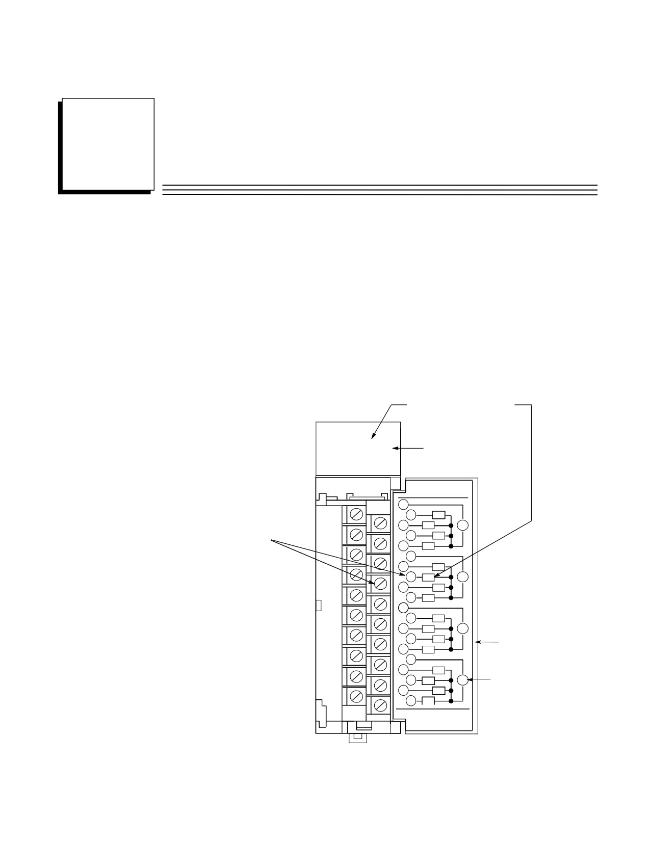
The following figure shows how the indicator LEDs correspond to the circuit connection points on
an I/O Module’s terminal board. The terminal board terminals are numbered from the top, with the
top terminal in the left row being number 1 and the top terminal in the right row being number 2.
The numbers alternate between rows with even numbers on the right and odd numbers on the left,
as shown in the circuit diagram on the back of the hinged cover.
LED A6 corresponds to circuit A6:
A1 2 3 4 5 6 7 8
F
Fuse Indicator LED
B1 2 3 4 5 6 7 8
OUTPUT
RELAY
2 AMP
1
2
A1
3
A2
V
Circuit A6 connects
4
A3
to terminal 8
5
A4
6
7
A5
8
A6
V
9
A7
10
A8
11
12
B1
13
B2
V
14
B3
Hinged Cover
15
B4
16
17
B5
18
B6
V
Indicates External
Power Supply
19
B7
20
B8
44A726782-015
FOR USE WITH
IC693MDL940
Figure 13-1. Relationship of Indicator Lights to Terminal Board Connections
GFK-0356Q
13-1
13
Module LED Indicators
Input Module LED Indicators
When a discrete input device closes, the corresponding input LED should light to indicate that the
signal reached the module. If the light does not turn ON, a voltage check can be made on the
module’s terminal board or block:
■ If the correct voltage is present at the terminal, the corresponding input bit can be checked in
the PLC with your programming software. If the software shows that the input bit is at logic 1,
the module’s LED circuit is defective.
■ If the correct voltage level is not present at the terminal, a check can be made at the input field
device to determine if the device or interconnecting wiring is defective.
If none of an input module’s inputs are working, it may be that the external (field) input power
supply is defective, not powered up, or not connected properly. (Input and output devices are
powered from an external power supply, not from inside the module). Input modules are not fused,
so the Fuse Indicator LED in the previous figure does not apply to them.
Output Module LED Indicators
When a discrete output address (%Q) is turned on in the ladder program, the corresponding output
LED should light to indicate that the signal reached the module.
■ If the light does not turn ON, the module may be defective or the LED light may be bad.
■ If the light turns on but the output device doesn’t operate, a voltage check can be made on the
module’s terminal board or block. If the correct voltage level is present there, the output
device or wiring should be checked.
If none of an output module’s outputs are working, it may be that the external (field) output power
supply is defective, is not powered up or is not connected properly. (Input and output devices are
powered from an external power supply, not from inside the module). If the output module is a
type that has built-in fuses (some have electronic short circuit protection instead), the Fuse
Indicator LED (labeled “F”), shown in the previous figure, will light if a fuse blows.
Power Supply LED Indicators
The power supplies have four LED indicators. Their functions are explained in the “Power
Supplies” chapter.
CPU LED Indicators
There are several different LED arrangements on the various CPUs. These are explained in the
“CPUs” chapter.
Option Module LED Indicators
There are numerous LED arrangements on the various option modules. The “Option Modules”
chapter has some information on this subject. It also directs you, for each module, to further
information in the “Documentation” heading for each module. Also, Appendix G contains a
catalog number to documentation cross-reference.
13-2
Series 90-30 PLC Installation and Hardware Manual - August 2002
GFK-0356Q
Maintenance and Troubleshooting
13
Troubleshooting Features of Programming Software
Detailed information about the following items are found in GFK-0467, Series 90-30/20/Micro
PLC CPU Instruction Set Reference Manual, and GFK-0466, Series 90-30/20/Micro Programming
Software User’s Manual.
Ladder Screens
Contacts, connections, and coils displayed on the ladder screens that are ON (passing power or
energized) are displayed in enhance brightness, allowing the tracing of signals through the
program. Addresses that refer to physical input (%I and %AI) and output signals (%Q and %AQ)
can be checked against module status lights, voltages, etc. to verify that the hardware is working
properly.
Configuration Screens
Normally, the following information is obtained from the system documentation. However, if they
are not available, the configuration screens can be used to determine:
• If the software configuration matches the actual hardware. Sometimes, while
troubleshooting, a module is installed in an incorrect slot by mistake. This will create a fault in
one of the two fault tables. The correct configuration can be determined from the
Configuration Screens.
• The memory addresses that a particular module is using.
Fault Tables
There are two fault tables, the “PLC Fault Table,” and the “I/O Fault Table.” The fault tables can
be viewed using the PLC programming software. These fault tables will not report such things as a
defective limit switch, but will identify system faults such as:
• Loss of or Missing Modules, System Configuration Mismatch.
• CPU hardware failure, Low Battery
• PLC Software Failure, Program Checksum Failure, No User Program, PLC Store Failures.
System Status References
These discrete references (%S, %SA, %SB, and %SC) can be viewed in the System Reference
(Status) Table, or on-screen if used in the ladder program, for determining the status of various
conditions and faults. For example, the %SC0009 bit turns on if a fault is logged in either fault
table. Another example is that bit %SA0011 will turn on if the CPU memory backup battery is low.
The Series 90-30 PLC CPU Instruction Set Reference Manual, GFK-0467, includes a “System
Status Reference Table.”
GFK-0356Q
Chapter 13 Maintenance and Troubleshooting
13-3
13
Reference Tables
There are two types of reference tables, standard and mixed. These tables show groups of memory
addresses and their status. For discrete addresses, the status of these will be shown as either logic 1
or logic 0. For analog and register addresses, values will be displayed. Standard tables display
only one type of memory address, such as all of the %I bits. Mixed reference tables are created by
the user, who selects what addresses to display in the tables. These mixed tables can contain
discrete, analog, and register references all in one table. This makes them useful for gathering
numerous related addresses on one screen where they can all be viewed or monitored at the same
time. This saves time compared with searching or scrolling through the ladder logic screens to find
these addresses.
Override feature
This feature must be used with caution to ensure the safety of personnel and equipment.
Normally, the machine should not be cycling, and all conditions should be such that the
output device can be turned on without any harm being done. This method can be used to
check an output circuit from the ladder screen all the way to the device being controlled. For
example, when overriding and toggling a %Q output to an ON state, the relay, solenoid, or other
device being controlled should turn on or pick up. If it does not, the status light on the output
module could be checked, then voltage checks could be made at the module terminal board, the
system terminal strip, the machinery terminal strip, the solenoid or relay connections, etc. until the
source of the fault is found.
Sequential Event Recorder (SER), DOIO functional instruction
These can be set up to capture the status of specified discrete addresses upon receiving a trigger
signal. They may be used to monitor and capture data about certain portions of the program, even
when unattended. They can be useful for locating the cause of an intermittent problem. For
example, a contact in a string of contacts that maintain power to a coil may, from time to time,
momentarily open and interrupt normal operation. However, when maintenance personnel attempt
to locate the problem, all of these contacts may test OK. By using the SER or DOIO instruction,
the status of all of these contacts can be captured within milliseconds of the time the fault occurs,
and the contact that opened will show a status of logic 0 at the moment of capture.
13-4
Series 90-30 PLC Installation and Hardware Manual - August 2002
GFK-0356Q
Maintenance and Troubleshooting
13
Replacing Modules
Modules do not contain configuration switches. The slot in each baseplate (rack) is configured
(using the configuration software) to hold a particular module type (catalog number). This
configuration information is stored in CPU memory. Therefore, when replacing a module, you do
not have to make any hardware settings on the module itself. You do, however, have to ensure that
you install the correct module type in a particular slot.
Be aware that some “intelligent” modules, such as the CPU, PCM, APM, or DSM302, may contain
application programs that will need to be reloaded after the module is replaced. For such modules,
make sure that up-to-date copies of the application programs are maintained in case they have to be
restored later.
For I/O modules with terminal boards, you do not have to rewire a new terminal board in order to
replace the module. If the old terminal board is not defective, it can be removed from the old
module and reinstalled on the new module without removing any of the wiring. Procedures for
removing and installing modules and terminal boards are found in Chapter 2.
Series 90-30 Product Repair
The Series 90-30 products are, for the most part, not considered to be field-repairable. The one
major exception are the few modules that have replaceable fuses. The next section, “Module Fuse
List,” identifies these modules and their applicable fuses.
GE Fanuc offers a repair/product warranty service through your local distributor. Contact your
distributor for details.
GFK-0356Q
Chapter 13 Maintenance and Troubleshooting
13-5

13
Module Fuse List
Warning
Replace fuse only with the correct size and type. Using an incorrect fuse can
result in harm to personnel, damage to equipment, or both.
Table 13-1. Fuse List for Series 90-30 Modules
Module
Current
Quantity on
GE Fanuc Fuse
Third Party Sources
Catalog
Module Type
Rating
Module
Part Number
and Part Numbers
Number
IC693CPU364
CPU Module with
1A
1
44A725214-001
Littlefuse - R454 001
embedded Ethernet
interface
IC693DVM300
Digital Valve Driver
1A
1
N/A
Bussman - GDB-1A
2A
4
N/A
Littlefuse - 239002
IC693MDL310
120 VAC, 0.5A
3A
2
44A724627-111 (1)
Bussman - GMC-3
Littlefuse - 239003
IC693MDL330
120/240 VAC, 1A
5A
2
44A724627-114 (1)
Bussman - GDC-5
Bussman S506-5
IC693MDL340
120 VAC, 0.5A
3A
2
44A724627-111 (1)
Bussman - GMC-3
Littlefuse -
239003
IC693MDL390
120/240 VAC, 2A
3A
5
44A724627-111 (1)
Bussman - GMC-3
Littlefuse -
239003
IC693MDL730
12/24 VDC Positive
5A
2
259A9578P16 (1)
Bussman - AGC-5
Logic, 2A
Littlefuse - 312005
IC693MDL731
12/24 VDC Negative
5A
2
259A9578P16 (1)
Bussman, AGC-5
Logic, 2A
Littlefuse - 312005
IC693PWR321
120/240 VAC or 125 VDC
2A
1
44A724627-109 (2)
Bussman - 215-002
and
Input, 30 Watt Power
(GDC-2 or GMC-2)
IC693PWR330
Supply
Littlefuse - 239-002
IC693PWR322
24/48 VDC Input,
5A
1
44A724627-114 (2)
Bussman - MDL-5
30 Watt Power Supply
Littlefuse - 313005
IC693PWR328
48 VDC Input
5A
1
44A724627-114 (2)
Bussman - MDL-5
30 Watt Power Supply
Littlefuse - 313005
IC693PWR331
24 VDC Input,
5A
1
44A724627-114 (2)
Bussman - MDL-5
30 Watt Power Supply
Littlefuse - 313005
IC693TCM302
Temperature Control
2A
1
N/A
Littlefuse - 273002
Module
(1) Mounted in clip. Accessible by removing circuit board from module housing.
(2) Line fuse. Mounted in clip - accessible by removing module front.
13-6
Series 90-30 PLC Installation and Hardware Manual - August 2002
GFK-0356Q

Maintenance and Troubleshooting
13
Spare/Replacement Parts
Two kits (IC693ACC319 and IC693ACC320) provide mechanical spare parts for Series 90-30
modules. One covers I/O CPU, PCM, and other modules; the other is for power supply modules.
These kits provide parts such as module levers, front covers, cases, etc. The following table
describes the contents of each kit.
Table 13-2. Spare/Replacement Parts
Spare Parts
Contents
IC693ACC319:
(qty. 10) I/O, CPU, PCM case lever
Spare parts kit for I/O, CPU,
(qty. 10) Spring pins cap
and PCM modules
(qty. 2) PCM module front cover
(qty. 2) PCM lens cap
(qty. 2) CPU module case
IC693ACC320:
(qty. 2) Power supply lever
Spare parts kit for power
(qty. 2) Spring pin for power supply lever
supplies
(qty. 2) Spring for power supply lever
(qty. 2) Power supply lens cap
(qty. 2) Power supply terminal cover
IC693ACC301 (see Note)
(qty. 2) Memory backup battery for CPU and PCM modules
Memory Backup Battery
Fuses
See “Fuse List For Series 90-30 Modules“ table in this chapter.
Modules
You may wish to maintain spare PLC modules. Many systems
have more than one of a particular catalog number, such as
power supplies (each rack has one) and I/O modules. In these
cases, one of each type would serve as backups for several
modules.
IC693ACC311
(qty. 6) Removable terminal boards used on many I/O
Removable Module Terminal
modules and some Option modules.
Board
44A736756-G01
Kit contains three sets (6 keys). Same key fits all applicable
CPU (CPU350 - 364) Key Kit
CPUs.
Note: The IC693ACC301 batteries have a shelf life of 5 years (see Chapter 6 for instructions on how to read battery
date codes). Periodically, outdated batteries should be removed from stock and disposed of according to the battery
manufacturer’s recommendations.
GFK-0356Q
Chapter 13 Maintenance and Troubleshooting
13-7

13
Preventive Maintenance Suggestions
Series 90-30 PLC Preventive Maintenance
Item
Description
Recommendation
No.
1
Safety ground and
Check frequently to ensure that safety ground connections are secure and
electrical system
that electrical cables and conduits are secure and in good condition.
2
CPU Memory backup
Replace annually or as appropriate for your application.* Check Chapter
battery
5 for instructions on how to avoid loss of memory contents when
replacing battery.
3
Option Module
Replace annually. Check user’s manual for additional instructions.
backup battery
Check Chapter 5 for instructions on how to avoid loss of memory
contents when replacing battery.
4
Ventilation
If using ventilation fan in enclosure, check for proper operation. Keep
fingers and tools away from moving fans. Clean or replace ventilation
air filter, if using one, at least monthly.
5
Mechanical tightness
With power OFF, check that connectors and modules are seated securely
in their sockets and that wire connections are secure. For low vibration
installations, perform annually. For high vibration installations, check at
least quarterly.
6
Enclosure
Check annually. With power OFF, remove manuals, prints, or other
loose material that could cause shorts or ventilation blockage, or that are
flammable, from inside of enclosure. Gently vacuum dust and dirt that
has collected on components. Use vacuum cleaner, not compressed air,
for this task.
7
Program backup
Do this initially after creating any application programs, such as the
ladder logic program, motion programs, etc. Then, any time a change is
made to a program, make at least one (several is better) new backup
copy. Keep old copies (clearly marked) for a reasonable period of time
in case you need to go back to the old design.
Document each backup copy as to what equipment it is for, date it was
created or modified, version number (if any), and author’s name.
Keep master backup copies in a safe place. Make working copies
available to those responsible for maintaining the equipment.
*See “Factors Affecting Battery Life” in Chapter 5.
13-8
Series 90-30 PLC Installation and Hardware Manual - August 2002
GFK-0356Q
Maintenance and Troubleshooting
13
Getting Additional Help and Information
There are several ways to get additional help and information:
GE Fanuc Web Site
There is a large amount of information on the Technical Support section of the GE Fanuc Web site.
Sections such as Technical Documentation, Application Notes, Revision Histories, Frequently
Asked Questions, and Field Service Bulletins may have the exact information you need. You can
access this site at:
Fax Link System
This system lets you choose technical help documents to be sent to you on your Fax machine. To
use this system follow these steps:
• Call Fax Link at (804) 978-5824 on a touch tone type phone (rotary dial phones will not work
for this application).
• Follow the instructions to have a master list (called “Document 1”) of Fax Link documents
Faxed to you. A master Fax Link list is also available on the GE Fanuc Web site in the
Technical Support section (see the “GE Fanuc Web Site” section above).
• Select desired document(s) from the master list, then call Fax Link and specify the document
number(s) you want to be Faxed to you. Up to three documents can be ordered per call.
GE Fanuc Telephone Numbers
If you need to speak with a GE Fanuc technical help person, use the applicable telephone number
from the following list.
Location
Telephone Number
North America, Canada, Mexico (Technical Support Hotline)
Toll Free:
800 GE Fanuc
Direct Dial: 804 978-6036
Latin America (for Mexico, see above)
Direct Dial: 804 978-6036
France, Germany, Luxembourg, Switzerland, and United Kingdom
Toll Free:
00800 433 268 23
Italy
Toll Free:
16 77 80 596
Other European Countries
+352 727 979 309
Asia / Pacific - Singapore
65 566 4918
India
91 80 552 0107
GFK-0356Q
Chapter 13 Maintenance and Troubleshooting
13-9
Appendix
Serial Ports and Cables
A
This appendix describes the serial port, converter, and cables used to connect Series 90 PLCs for
Series 90 Protocol (SNP). This information is included for reference and for those users who have
applications that require cable lengths different than the factory-supplied cables.
This appendix contains the following information:
■ Communications Interface
■ Cable and Connector Specifications
■ Serial Port Configuration
■ RS-232/RS-485 Converter (Catalog No. IC690ACC900)
■ Serial Cable Diagrams
Point-to-Point Connection
Multidrop Connection
RS-422 Interface
The Series 90 PLC family of products are compatible with EIA RS-422 specifications. RS-422
drivers and receivers are utilized to accomplish communications between several system
components using multiple driver/receiver combinations on a single cable with five twisted pairs.
The cable length between master and any slave cannot exceed 4,000 (1,219 meters) feet.
A multi-drop system of eight drivers and receivers can be configured. The maximum common
mode voltage between each additional drop is the RS-422 standard of +7 Volts to -7 Volts. The
driver output must be capable of 2 V minimum into 100 ohms. The driver output impedance must
be at least 120 K ohms in the high impedance state. The receiver input resistance is 12 K ohms or
greater. Receiver sensitivity is 200 millivolt.
Caution
Care must be taken that common mode voltage specifications are met.
Common mode conditions that exceed those specified will result in errors in
transmission and/or damage to Series 90 PLC components. When the
common mode voltage specification is exceeded, a port isolator such as the
IC690ACC903 must be used. See Appendix E for details on this port
isolator.
GFK-0356Q
A-1

A
Cable and Connector Specifications
The cable assembly presents one of the most common causes of communication failure. For best
performance construct the cable assemblies according to the recommended connector parts and
specifications.
Table A-1. Connector/Cable Specifications
Item
Description
Series 90 PLC: Serial (RS-422) port with metric hardware
Connector: 15-pin male, D-Subminiature Type, Cannon DA15S (solder pot) Hood: AMP
207470-1 connector shell
Hardware Kit: AMP 207871-1 Kit includes 2 metric screws and 2 screw clips
Workmaster II: Serial (RS-232) port with standard RS-232 connector
Mating
Connector: 25-pin female, D-Subminiature Type, Cannon DB25S (solder pot) with
Connectors:
DB110963-3 hood or equivalent (standard RS-232 connector)
Workmaster: Serial (RS-232) port with standard RS-232 connector
Connector: 9-pin female, D-Subminiature Type, Cannon DE9S (solder pot) with DE110963-1
hood or equivalent (standard RS-232 connector)
IBM-AT/XT: Serial (RS-232) port with standard RS-232 connector
Connector: 9-pin female, D-Subminiature Type, Cannon DE9S (solder pot) with DE110963-31
hood or equivalent (standard RS-232 connector)
RS-232/RS-485 Converter: one 15-pin male, and one 25-pin male
connector
15-pin male connector requires metric hardware (same connector, hood, and hardware as for
Series 90 PLC listed above)
25-pin male D-Subminiature Type, Cannon DA25S (solder pot) with DB110963-3 hood or
equivalent (standard RS-232 connector)
Computer grade, 24 AWG (.22 mm2), minimum with overall shield
Catalog Numbers: Belden 9505, Belden 9306, Belden 9832
Cable:
These cables provide acceptable operation for data rates up to 19.2 Kbps
as follows:
RS-232: 50 feet (15 meters) maximum cable length
RS-422/RS-422:
4000 feet (1200 meters) maximum length. Must not
exceed the maximum RS-422 Common Mode specifi-
cation of +7V to -7V. Isolation at the remote end may
be used to reduce or eliminate Common Mode voltages.
For distances under 50 feet (15 meters), almost any twisted pair or shielded twisted pair cable
will work, as long as the wire pairs are connected correctly.
When using RS-422/RS-422, the twisted pairs should be matched so that both transmit signals
make up one twisted pair and both receive signals make up the other twisted pair. If this is
ignored, cross-task resulting from the mismatching will affect the performance of the
communications system.
When routing communication cables outdoors, transient suppression devices can be used to
reduce the possibility of damage due to lightning or static discharge.
Care should be exercised that all connected devices are grounded to a common point.
Failure to do so could result in damage to the equipment.
A-2
Series 90-30 PLC Installation and Hardware Manual - August 2002
GFK-0356Q
Serial Ports and Cables
A
Series 90 PLC Serial Port
The Series 90 PLC serial port is compatible with RS-422. An RS-232 to RS-422 converter is
required to interface to systems that provide RS-232 compatible interfaces. The Series 90 PLC
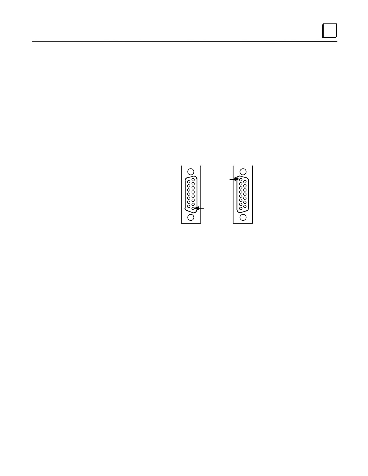
RS-422 serial port provides the physical connection for SNP communication. This port is a 15-pin
D-type female connector located as follows:
■ Series 90-70 PLC and Series 90-20 - CPU Module
■ Series 90-30 PLC - Power Supply
Figure A-1 shows the serial port orientation and connector layout for the Series 90 PLC types.
(The orientation of the connector on the Series 90-20 CPU is rotated 90 degrees from the Series
90-30 connector with pin 1 to the upper right.) Table A-2 shows the pin numbering and signal
assignment applicable to both PLCs.
SERIES 90-70 PLC
SERIES 90-30 PLC
PIN
8
1
15
9
PIN
9
1
15
8
NOTE
SERIES 90 PLC CONNECTORS
USE METRIC HARDWARE.
(SEE CONNECTOR SPECIFICATIONS)
Figure A-1. Series 90 PLC, RS-422 Serial Port Connector Configuration
GFK-0356Q
Appendix A Serial Ports and Cables
A-3
A
Table A-2. Series 90 PLC, RS-422 Serial Port Pin-out
Pin Number
Signal Name
Description
1
Shield
2
No Connection
3
No Connection
4
ATCH *
Hand-Held Programmer attach signal
5
+5V *
+5V Power for: HHP and RS-232/485 Converter
6
RTS (A)
Request To Send
7
Signal Ground
Signal Ground, OV
8
CTS (B’)
Clear To Send
9
RT *
Terminating Resistor for RD **
10
RD (A’)
Receive Data
11
RD (B’)
Receive Data
12
SD (A)
Send Data
13
SD (B)
Send Data
14
RTS (B)
Request To Send
15
CTS (A’)
Clear To Send
* Signals available at the Connector but are not included in the RS-422 specification.
SD (Send Data) and RD (Receive Data) are the same as TXD and RXD (used in the Series Six
PLC).
(A) and (B) are the same as - and +. A and B denote outputs, and A’ and B’ denote inputs.
** Termination resistance for the Receive Data (RD) signal needs to be connected only on units at the
end of the lines. This termination is made on the Series 90 PLC products by connecting a jumper
between pins 9 and 10 inside the 15-pin D-shell with the following exception
For Series 90-70 PLCs with Catalog Numbers IC697CPU731J, and IC697CPU771G and earlier the
termination for RD at the PLC is implemented by a jumper between pins 9 and 11.
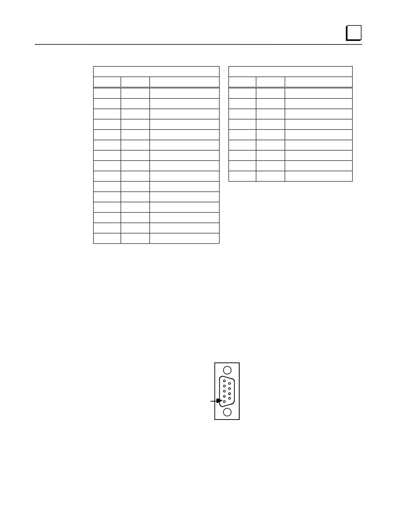
Workmaster Serial Port
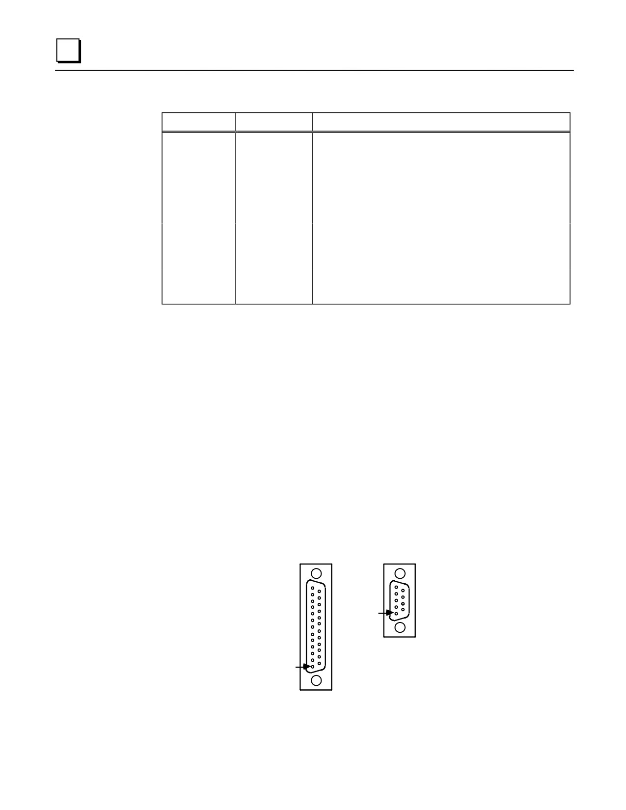
The Workmaster II industrial computer, RS-232 serial port is a 25-pin D-type male connector, and
the early model Workmaster is a 9-pin male connector.
Figure A-2 shows the serial port connector layout for both computers. Table A-3 shows the pin
numbering and signal assignment for both connector types.
a44522
WORKMASTER II
WORKMASTER
(EARLY MODEL)
13
5
25
9
PIN
6
1
PIN
12
1
Figure A-2. Workmaster RS-232 Serial Port Connector Configuration
A-4
Series 90-30 PLC Installation and Hardware Manual - August 2002
GFK-0356Q
Serial Ports and Cables
A
Table A-3. Workmaster RS-232 Serial Port Pins-out
Workmaster II (25-pin connector)
Workmaster (9-pin connector)
Pin No.
Signal
Description
Pin No.
Signal
Description
1
NC
1
NC
2
TD
Transmit Data
2
TD
Transmit Data
3
RD
Receive Data
3
RD
Receive Data
4
RTS
Request to Send
4
RTS
Request to Send
5
CTS
Clear to Send
5
CTS
Clear to Send
6
NC
6
NC
7
GND
Signal Ground
7
GND
Signal Ground, 0V
8
DCD
Data Carrier Detect
8
DCD
Data Carrier Detect
9,10
NC
9
DTR
Data Terminal Ready
11
Tied to line 20
NC = Not Connected
12-19
NC
20
DTR
Data Terminal Ready
21
NC
22
Ring Indicate
23-25
NC
For more information about the Workmaster industrial computer serial port refer to the following
manuals:
GFK-0401 Workmaster II PLC Programming Unit Guide to Operation
GEK-25373 Workmaster Programmable Control Information Center Guide to Operation
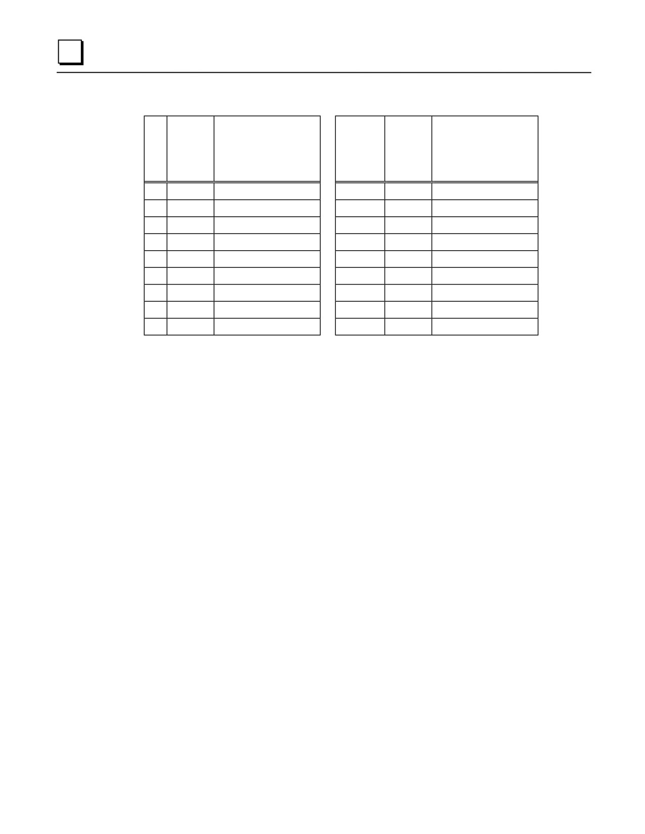
IBM-AT/XT Serial Port
The IBM-AT, IBM-XT or compatible computer’s RS-232 serial port is a 9-pin D-type male
connector as shown in the figure below.
a44523
IBM-AT/XT
5
9
PIN
1
6
Figure A-3. IBM-AT/XT Serial Port
GFK-0356Q
Appendix A Serial Ports and Cables
A-5
A
Table A-4. IBM-AT/XT Serial Port Pins-out
IB
IBM-XT
M-
Signal
Description
Pin No.
Signal
Description
AT
Pin
No.
1
DCD
Data Carrier Detect
1
NC
2
RD
Receive Data
2
TD
Transmit Data
3
TD
Transmit Data
3
RD
Receive Data
4
DTR
Data Terminal Ready
4
RTS
Request to Send
5
GND
Signal Ground
5
CTS
Clear to Send
6
NC
6
NC
7
RTS
Request to Send
7
GND
Signal Ground
8
CTS
Clear to Send
8
DCD
Data Carrier Detect
9
NC
9
DTR
Data Terminal Ready
NC = Not Connected
A-6
Series 90-30 PLC Installation and Hardware Manual - August 2002
GFK-0356Q
Serial Ports and Cables
A
RS-232/RS-485 Converter
IC690ACC901 Miniconverter Kit
This kit consists of an RS-422 to RS-232 miniconverter, a 6 foot (2 meter) serial cable, and a 9-pin
to 25-pin serial port converter plug. This miniconverter is documented in Appendix D. This
miniconverter has replaced the older, larger, obsolete IC690ACC900 converter.
IC690ACC900 Obsolete Converter
The obsolete RS-232/RS-485 Converter (IC690ACC900) converts from RS-232 to RS-422/RS-485
communications. The converter has one 15-pin female D-type port, and one 25-pin female D-type
port.
This converter is no longer available. Please substitute the IC690ACC901 miniconverter.
Information about this converter is included in this manual for reference and troubleshooting
purposes.
For detailed information on the converter, refer to Appendix D. Examples of serial cable diagrams,
which include the converter, are provided in the remainder of this appendix..
GFK-0356Q
Appendix A Serial Ports and Cables
A-7
A
Serial Cable Diagrams
This section describes only a few of the many and various Point-to-Point, and Multidrop serial port
connections for Series 90 PLCs.
In the point-to-point configuration only two devices can be connected to the same communication
line. The communication line can be directly connected using RS-232 (50 feet, 15 meters
maximum) or RS-485 (4000 feet, 1200 meters maximum). Modems can be used for longer
distances.
Note
The cable connector for the Series 90-70 and Series 90-30 PLCs serial port must
be a right angle connector in order for the hinged door on the module to close
properly. Refer to Table A-1 Connector/Cable Specification.
RS-232 Point-to-Point Connections
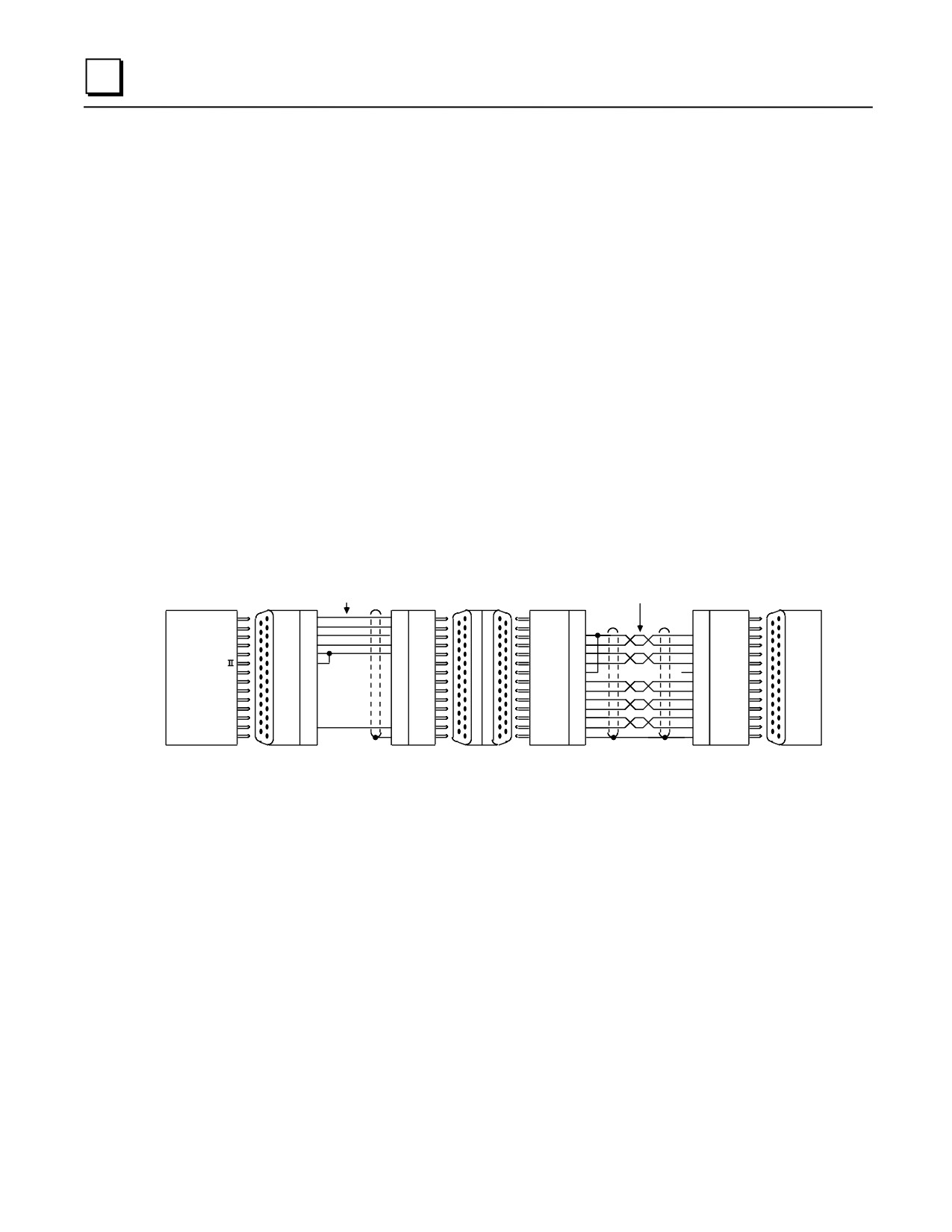
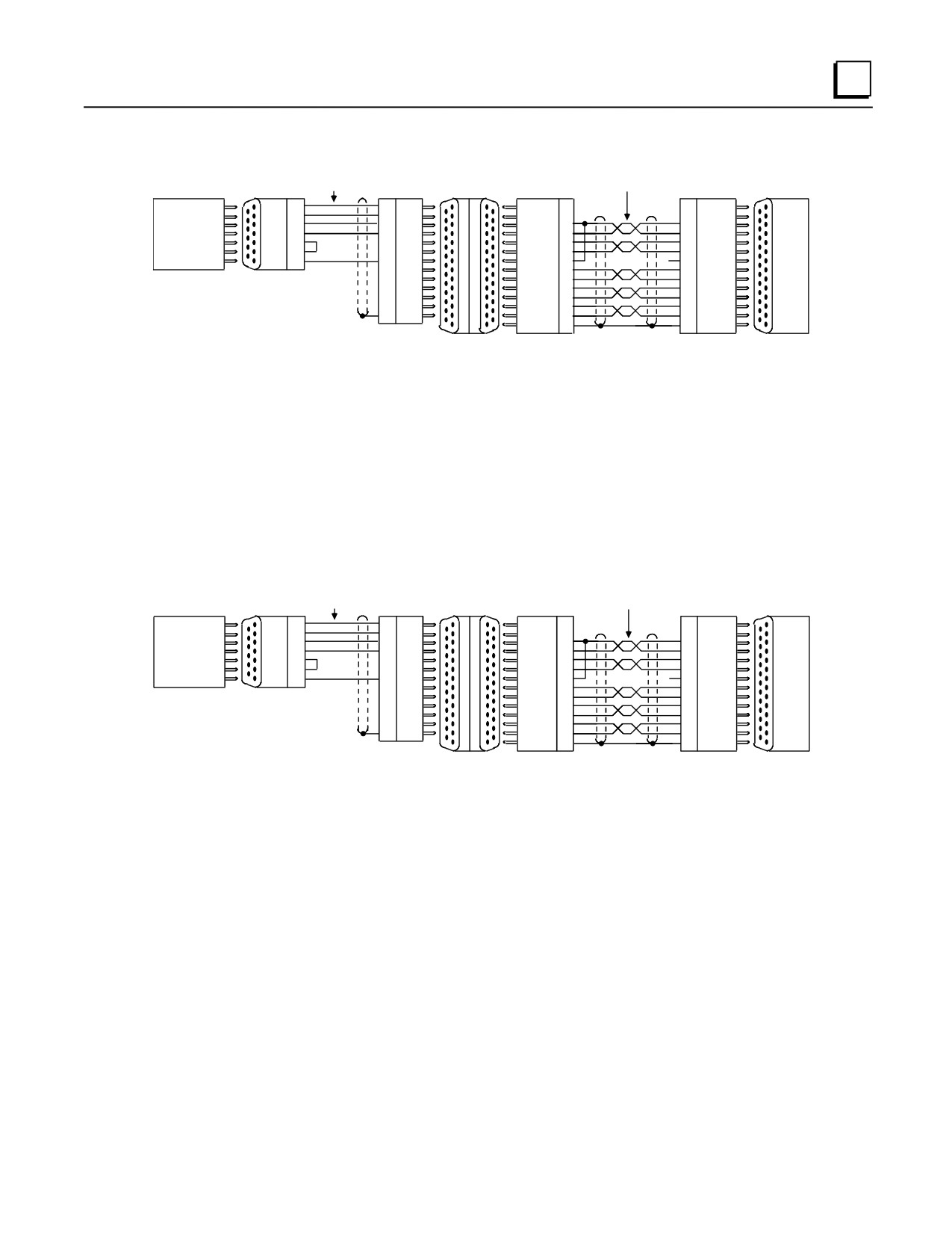
The next three figures illustrate typical RS-232 point-to-point connection to Series 90 PLCs.
IC690CBL705 OR EQUIVALENT
RS-232/RS-485
RS-422
RS-232
CONVERTER
TWISTED SHIELDED
a44506
SHIELDED PAIRS
(IC690ACC900)
PAIRS
PIN
PIN
PIN
PIN
TD
2
3
RD
DCD ( B )
2
2
RD
3
2
TD
DCD ( A )
3
3
SD ( A )
RTS
4
5
CTS
RD ( B' )
10
12
SD ( B )
CTS
5
4
RTS
RD ( A' )
11
13
RD ( A' )
DCD
8
8
DCD
SD ( B )
12
10
RD ( B ' )
SERIES
DTR
20
7
GND
SD ( A )
13
11
RD
90 PLC
WORKMASTER
GND
7
1
SHLD
RT
9
9
RTS ( B )
RS-422
CTS ( B' ) 15
**
6
RTS ( A )
PORT
RS-232
CTS ( A' )
8
14
CTS ( A' )
PORT
RTS ( A )
6
15
CTS ( B' )
RTS ( B ) 14
8
+5V
+5V
5
5
0V
0V
7
7
SHLD
SHLD
1
1
25-PIN
25-PIN
25-PIN
25-PIN
15-PIN
15- PIN
15- PIN
15- PIN
MALE
FEMALE
MALE
FEMALE FEMALE
MALE
MALE
FEMALE
RS-232
RS-485
PORT
PORT
POWER SOURCE FOR POINT-TO-POINT CONNECTION 10 FEET (3 METERS) ONLY. CONVERTER POWER SOURCE BEYOND 10 FEET (3 METERS) AND FOR MULTIDROP
CONNECTION MUST BE EXTERNAL SOURCE.
**
TERMINATION RESISTANCE FOR THE RECEIVE DATA (RD) SIGNAL NEEDS TO BE CONNECTED ONLY ON UNITS AT THE END OF THE LINES. THIS TERMINATION IS MADE ON
THE SERIES 90 PLC PRODUCTS BY CONNECTING A JUMPER BETWEEN PIN 9 AND PIN 10 INSIDE THE 15-PIN D-SHELL WITH THE FOLLOWING EXCEPTION. FOR SERIES
90-70 PLCs, CATALOG NUMBERS IC697CPU731 AND IC697CPU771, THE TERMINATION FOR RD AT THE PLC IS IMPLEMENTED BY A JUMPER BETWEEN PIN 9 AND PIN 11.
A-8
Series 90-30 PLC Installation and Hardware Manual - August 2002
GFK-0356Q
Serial Ports and Cables
A
IC690CBL702 OR EQUIVALENT
RS-232/RS-422
RS-422
RS-232
CONVERTER
TWISTED SHIELDED
a44507
SHIELDED PAIRS
(IC690ACC900)
PAIRS
PIN
PIN
PIN
PIN
RD
2
2
TD
DCD ( A )
2
2
IBM-AT
TD
3
3
RD
DCD ( B )
3
3
SD ( A )
(COMPATIBLE)
RTS
7
5
CTS
RD ( A' )
10
12
SD ( B )
CTS
8
20
DTR
RD ( B' )
11
13
RD ( A' )
DCD
1
8
DCD
SD ( A )
12
10
RD ( B )
RS-232
DTR
4
7
GND
SD ( B )
13
11
RD
SERIES
PORT
GND
5
1
SHLD
RT
9
9
RTS ( A )
90 PLC
CTS ( A' )
15
6
RTS ( B )
RS-422
**
PORT
CTS ( B' )
8
14
CTS ( A' )
9-PIN
9-PIN
RTS ( A )
6
15
CTS ( B' )
MALE
FEMALE
RTS ( B )
14
8
+5V
+5V
5
5
0V
0V
7
7
SHLD
SHLD
1
1
25-PIN
MALE
25-PIN
15-PIN
15- PIN
15- PIN
15- PIN
FEMALE FEMALE
MALE
MALE
FEMALE
RS-232
RS-422
PORT
PORT
POWER SOURCE FOR POINT-TO-POINT CONNECTION 10 FEET (3 METERS) ONLY. CONVERTER POWER SOURCE BEYOND 10 FEET (3 METERS) AND FOR MULTIDROP CONNECTION
MUST BE EXTERNAL SOURCE.
**
TERMINATION RESISTANCE FOR THE RECEIVE DATA (RD) SIGNAL NEEDS TO BE CONNECTED ONLY ON UNITS AT THE END OF THE LINES. THIS TERMINATION IS MADE ON THE
SERIES 90 PLC PRODUCTS BY CONNECTING A JUMPER BETWEEN PIN 9 AND PIN 10 INSIDE THE 15-PIN D-SHELL WITH THE FOLLOWING EXCEPTION. FOR SERIES 90-70 PLCs,
CATALOG NUMBERS IC697CPU731 AND IC697CPU771, THE TERMINATION FOR RD AT THE PLC IS IMPLEMENTED BY A JUMPER BETWEEN PIN 9 AND PIN 11.
Figure A-4. IBM-AT (compatibles) Personal Computer to Series 90 PLCs
IC690CBL701 OR EQUIVALENT
RS-232/RS-422
RS-422
a44508
RS-232
CONVERTER
TWISTED SHIELDED
SHIELDED PAIRS
(IC690ACC900)
PAIRS
PIN
PIN
PIN
PIN
TD
2
3
RD
DCD ( A )
2
2
SD ( A )
IBM-XT
RD
3
2
TD
DCD ( B )
3
3
SD ( B )
OR
RTS
4
5
CTS
RD ( A' )
10
12
RD ( A' )
WORKMASTER
CTS
5
20
DTR
RD ( B' )
11
13
RD ( B' )
DCD
8
8
DCD
SD ( A )
12
10
RD
DTR
9
7
GND
SD ( B )
13
11
RTS ( A )
SERIES
RS-232
GND
7
1
SHLD
RT
9
9
RTS ( B )
90 PLC
PORT
CTS ( A' )
15
6
CTS ( A' )
RS-422
**
PORT
CTS ( B' )
8
14
CTS ( B')
9-PIN
9-PIN
RTS ( A )
6
15
+5V
MALE
FEMALE
RTS ( B )
14
8
0V
+5V
5
5
SHLD
0V
7
7
SHLD
1
1
25-PIN
MALE
25-PIN
15-PIN
15- PIN
15- PIN
15- PIN
FEMALE FEMALE
MALE
MALE
FEMALE
RS-232
RS-422
PORT
PORT
POWER SOURCE FOR POINT-TO-POINT CONNECTION 10 FEET (3 METERS) ONLY. CONVERTER POWER SOURCE BEYOND 10 FEET (3 METERS) AND FOR MULTIDROP
CONNECTION MUST BE EXTERNAL SOURCE.
**
TERMINATION RESISTANCE FOR THE RECEIVE DATA (RD) SIGNAL NEEDS TO BE CONNECTED ONLY ON UNITS AT THE END OF THE LINES. THIS TERMINATION IS MADE ON
THE SERIES 90 PLC PRODUCTS BY CONNECTING A JUMPER BETWEEN PIN 9 AND PIN 10 INSIDE THE 15-PIN D-SHELL WITH THE FOLLOWING EXCEPTION. FOR SERIES 90-70
PLCs, CATALOG NUMBERS IC697CPU731 AND IC697CPU771, THE TERMINATION FOR RD AT THE PLC IS IMPLEMENTED BY A JUMPER BETWEEN PIN 9 AND PIN 11.
Figure A-5. Workmaster or IBM-XT (compatibles) Personal Computer to Series 90 PLCs
GFK-0356Q
Appendix A Serial Ports and Cables
A-9
A
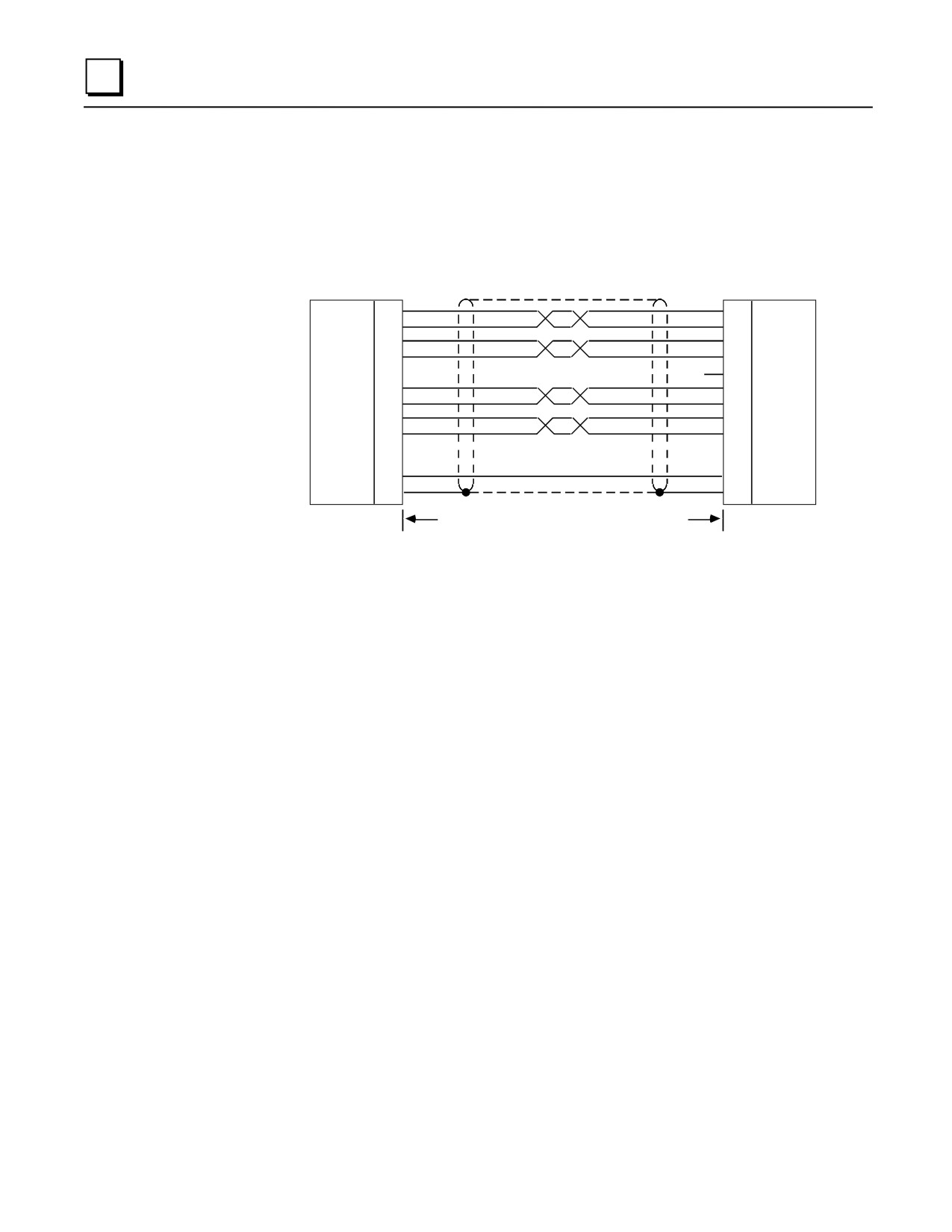
RS-422 Point-to-Point Connection
If your host device is equipped with a RS-422 card you can connect directly to Series 90 PLCs as
illustrated in Figure A-6.
HOST
PLC
COMPUTER
PIN
SHIELDED TWISTED PAIRS
PIN
RD (A')
12
SD ( A )
RD (B')
13
SD ( B )
10
RD ( A' )
SD (A)
11
RD ( B ' )
SD (B)
9
RD
6
RTS ( A )
CTS (A')
14
RTS ( B )
8
CTS ( B' )
CTS (B')
15
CTS ( A' )
RTS (B')
3
GND
RTS (A)
2
SHLD
7
1
GND
SHLD
UP TO A MAXIMUM OF 50 FEET (15.2 METERS)
(WITHOUT ISOLATION)
* TERMINATION RESISTANCE FOR THE RECEIVE DATA (RD) SIGNAL NEEDS TO
CONNECTED ONLY ON UNITS AT THE END OF THE LINES. THIS TERMINATION IS
ON THE SERIES 90 PLC PRODUCTS BY CONNECTING A JUMPER BETWEEN PIN 9
PIN 10 INSIDE THE 15-PIN D-SHELL WITH THE FOLLOWING EXCEPTION. FOR
90-70 PLCs, CATALOG NUMBERS IC697CPU731 AND IC697CPU771, THE
O
FOR RD AT THE PLC IS IMPLEMENTED BY A JUMPER BETWEEN PIN 9 AND PIN
Figure A-6. Typical RS-422, Host to PLC Connection, with Handshaking
Multidrop Connections
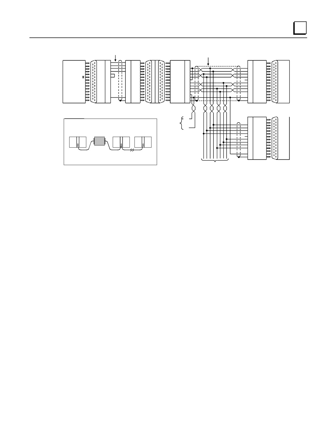
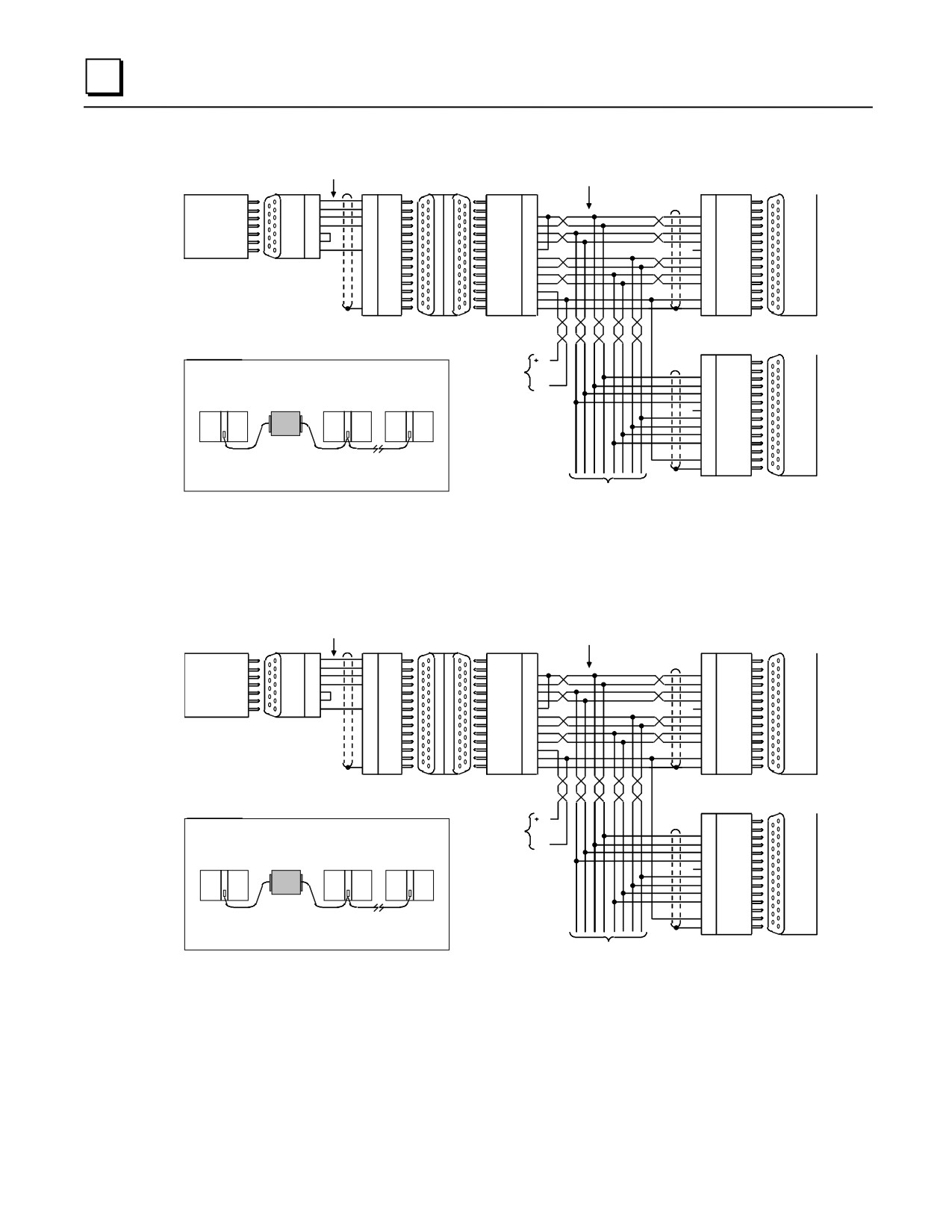
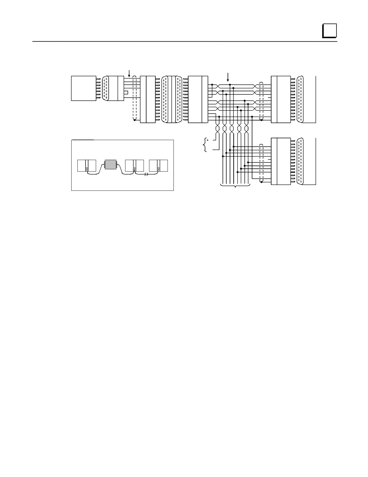
In the multidrop configuration, the host device is configured as the master and one or more PLCs
are configured as slaves. This method can be used when the maximum distance between the master
and any slave does not exceed 4000 feet (1200 meters). This figure assumes good quality cables
and a moderately noisy environment. A maximum of 8 slaves can be connected using RS-422 in a
daisy chain or multidrop configuration. The RS-422 line must include handshaking and use wire
type as specified in the “Cable and Connector Specifications” section.
The following illustrations shows wiring diagrams and requirements for connecting a
Workmaster II or IBM-PS/2, Workmaster, IBM-AT/XT or compatible computer to Series 90 PLCs
in an 8-wire multidrop, serial data configuration.
A-10
Series 90-30 PLC Installation and Hardware Manual - August 2002
GFK-0356Q
Serial Ports and Cables
A
IC690CBL705 OR EQUIVALENT
RS-232/RS-422
RS-422
RS-232 SHIELDED PAIRS
CONVERTER
MAKE CONNECTIONS
(IC690ACC900)
INSIDE D-CONNECTORS
SLAVE
PIN
PIN
PIN
PIN
STATION
TD
2
3
RD
DCD ( A )
2
2
SD ( A )
RD
3
2
TD
DCD ( B )
3
3
SD ( B )
RTS
4
5
CTS
RD ( A' )
10
12
RD ( A' )
CTS
5
20
DTR
RD ( B' )
11
13
RD ( B' )
SERIES
DCD
8
8
DCD
SD ( A )
12
10
RD
90-70
DTR
20
7
GND
SD ( B )
13
11
RTS ( A )
CPU
WORKMASTER
GND
7
1
SHLD
RT
9
9
RTS ( B )
RS-422
CTS ( A' )
15
6
CTS ( A' )
PORT
RS-232
CTS ( B' )
8
14
CTS ( B' )
PORT
RTS ( A )
6
15
+5V
RTS ( B )
14
8
0V
+5V
5
5
SHLD
0V
7
7
SHLD
1
1
25- PIN
25- PIN
25- PIN
25-PIN
15-PIN
15- PIN
15- PIN
15- PIN
MALE
FEMALE
MALE
FEMALE
FEMALE
MALE
MALE
FEMALE
RS-232
RS-422
PORT
PORT
LAST
PIN
STATION
POWER
5V
2
SD ( A )
NOTE
SOURCE
3
SD ( B )
WHEN WIRING RS-422 /485 MULTIDROP CABLES REFLECTIONS ON THE
FOR
12
RD ( A' )
TRANSMISSION LINE CAN BE REDUCED BY CONFIGURING THE CABLE IN A
CONVERTER
13
RD ( B' )
SERIES
DAISY
0V
10
RD
90-30
CHAIN FASHION AS SHOWN BELOW.
11
RTS ( A )
PS
MASTER
CONVERTER
SLAVE STATION
LAST STATION
9
RTS ( B )
RS-422
*
6
CTS ( A' )
PORT
PLC 15-PIN CONNECTOR
14
CTS ( B' )
SERIES 90-30 LOCATED
15
+5V
ON POWER SUPPLY
8
0V
SERIES 90-70 LOCATED
5
SHLD
ON THE CPU BOARD
7
1
ALSO IT IS RECOMMENDED TO MAKE ANY NECESSARY CONNECTIONS
INSIDE THE CABLE CONNECTOR TO BE MOUNTED ON THE PLC. IT IS
NOT RECOMMENDED TO USE TERMINAL STRIPS TO OTHER TYPES OF
CONNECTORS ALONG THE LENGTH OF THE TRANSMISSION LINE.
15- PIN
15- PIN
TO OTHER PLC's
MALE
FEMALE
* TERMINATION RESISTANCE FOR THE RECEIVE DATA (RD) SIGNAL NEEDS TO BE CONNECTED ONLY ON UNITS AT THE END OF THE LINES. THIS TERMINATION IS MADE
ON THE SERIES 90 PLC PRODUCTS BY CONNECTING A JUMPER BETWEEN PIN 9 AND PIN 10 INSIDE THE 15-PIN D-SHELL WITH THE FOLLOWING EXCEPTION. FOR SERIES
90-70 PLCs, CATALOG NUMBERS IC697CPU731 AND IC697CPU771, THE TERMINATION FOR RD AT THE PLC IS IMPLEMENTED BY A JUMPER BETWEEN PIN 9 AND PIN 11.
GROUND POTENTIAL: MULTIPLE UNITS, NOT CONNECTED TO THE SAME POWER SOURCE, MUST HAVE COMMON GROUND POTENTIALS OR GROUND ISOLATION FOR PROPER
OPERATION OF THIS SYSTEM.
Figure A-7. Workmaster II/Series 90 PLC Multidrop Connection
Note
The cable connector for the Series 90-70 serial port must be a right
angle
connector in order for the hinged door on the module to close properly. Refer to
Table A-1, “Connector/Cable Specification.”
GFK-0356Q
Appendix A Serial Ports and Cables
A-11
A
IC690CBL701 OR EQUIVALENT
RS-232/RS-422
RS-422
RS-232 SHIELDED PAIRS
CONVERTER
MAKE CONNECTIONS
(IC690ACC900)
INSIDE D-CONNECTORS
SLAVE
PIN
PIN
PIN
PIN
STATION
TD
2
3
RD
DCD ( A )
2
2
SD ( A )
RD
3
2
TD
DCD ( B )
3
3
SD ( B )
WORKMASTER
RTS
4
5
CTS
RD ( A' )
10
12
RD ( A' )
CTS
5
20
DTR
RD ( B' )
11
13
RD ( B' )
SERIES
DCD
8
8
DCD
SD ( A )
12
10
RD
90-70
RS-232
DTR
9
7
GND
SD ( B )
13
11
RTS ( A )
CPU
PORT
GND
7
1
SHLD
RT
9
9
RTS ( B )
RS-422
CTS ( A' )
15
6
CTS ( A' )
PORT
CTS ( B' )
8
14
CTS ( B' )
9- PIN
9- PIN
RTS ( A )
6
15
+5V
MALE
FEMALE
RTS ( B )
14
8
0V
+5V
5
5
SHLD
0V
7
7
SHLD
1
1
25- PIN
25-PIN
15-PIN
15- PIN
15- PIN
15- PIN
MALE
FEMALE
FEMALE
MALE
MALE
FEMALE
RS-232
RS-422
PORT
PORT
LAST
PIN
STATION
POWER
5V
2
NOTE
SOURCE
3
SD ( A )
WHEN WIRING RS-422 /485 MULTIDROP CABLES REFLECTIONS ON THE
FOR
12
SD ( B )
TRANSMISSION LINE CAN BE REDUCED BY CONFIGURING THE CABLE
CONVERTER
0V
13
RD ( A' )
SERIES
IN A DAISY
CHAIN FASHION AS SHOWN BE
10
RD ( B' )
90-30
11
RD
PS
LOW.
RS-422
MASTER
CONVERTER
SLAVE STATION
LAST STATION
9
RTS ( A )
6
RTS ( B )
PORT
PLC 15-PIN CONNECTOR
14
CTS ( A' )
SERIES 90-30 LOCATED
15
CTS ( B' )
ON POWER SUPPLY
8
+5V
SERIES 90-70 LOCATED
5
0V
ON THE CPU BOARD
7
SHLD
1
ALSO IT IS RECOMMENDED TO MAKE ANY NECESSARY CONNECTIONS
INSIDE THE CABLE CONNECTOR TO BE MOUNTED ON THE PLC. IT IS
NOT RECOMMENDED TO USE TERMINAL STRIPS TO OTHER TYPES OF
CONNECTORS ALONG THE LENGTH OF THE TRANSMISSION LINE.
15- PIN
15- PIN
TO OTHER PLC's
MALE
FEMALE
* TERMINATION RESISTANCE FOR THE RECEIVE DATA (RD) SIGNAL NEEDS TO BE CONNECTED ONLY ON UNITS AT THE END OF THE LINES. THIS TERMINATION IS MADE ON THE
SERIES 90 PLC PRODUCTS BY CONNECTING A JUMPER BETWEEN PIN 9 AND PIN 10 INSIDE THE 15-PIN D-SHELL WITH THE FOLLOWING EXCEPTION. FOR SERIES 90-70 PLCs,
CATALOG NUMBERS IC697CPU731 AND IC697CPU771, THE TERMINATION FOR RD AT THE PLC IS IMPLEMENTED BY A JUMPER BETWEEN PIN 9 AND PIN 11.
GROUND POTENTIAL: MULTIPLE UNITS, NOT CONNECTED TO THE SAME POWER SOURCE, MUST HAVE COMMON GROUND POTENTIALS OR GROUND ISOLATION FOR PROPER
OPERATION OF THIS SYSTEM.
Figure A-8. Workmaster/Series 90 PLC Multidrop Connection
IC690CBL702 OR EQUIVALENT
RS-232/RS-422
RS-422
RS-232 SHIELDED PAIRS
CONVERTER
MAKE CONNECTIONS
(IC690ACC900)
INSIDE D-CONNECTORS
SLAVE
PIN
PIN
PIN
PIN
STATION
TD
2
2
RD
DCD ( A )
2
2
SD ( A )
IBM-AT
RD
3
3
TD
DCD ( B )
3
3
SD ( B )
(COMPATIBLE)
RTS
7
5
CTS
RD ( A' )
10
12
RD ( A' )
CTS
8
20
DTR
RD ( B' )
11
13
RD ( B' )
SERIES
DCD
1
8
DCD
SD ( A )
12
10
RD
90-70
RS-232
DTR
4
7
GND
SD ( B )
13
11
RTS ( A )
CPU
PORT
GND
5
1
SHLD
RT
9
9
RTS ( B )
RS-422
CTS ( A' )
15
6
CTS ( A' )
PORT
CTS ( B' )
8
14
CTS ( B' )
9- PIN
9- PIN
RTS ( A )
6
15
+5V
MALE
FEMALE
RTS ( B )
14
8
0V
+5V
5
5
SHLD
0V
7
7
SHLD
1
1
25- PIN
25-PIN
15-PIN
15- PIN
15- PIN
15- PIN
MALE
FEMALE
FEMALE
MALE
MALE
FEMALE
RS-232
RS-422
PORT
PORT
LAST
PIN
STATION
POWER
5V
2
NOTE
SOURCE
3
SD ( A )
WHEN WIRING RS-422 /485 MULTIDROP CABLES REFLECTIONS ON THE
FOR
12
SD ( B )
13
RD ( A' )
SERIES
TRANSMISSION LINE CAN BE REDUCED BY CONFIGURING THE CABLE
CONVERTER
0V
90-30
IN A DAISY
CHAIN FASHION AS SHOWN BE
10
RD ( B' )
LOW.
11
RD
PS
MASTER
CONVERTER
SLAVE STATION
LAST STATION
9
RTS ( A )
RS-422
*
6
RTS ( B )
PORT
PLC 15-PIN CONNECTOR
14
CTS ( A' )
SERIES 90-30 LOCATED
15
CTS ( B' )
ON POWER SUPPLY
8
+5V
SERIES 90-70 LOCATED
5
0V
ON THE CPU BOARD
7
SHLD
1
ALSO IT IS RECOMMENDED TO MAKE ANY NECESSARY CONNECTIONS
INSIDE THE CABLE CONNECTOR TO BE MOUNTED ON THE PLC. IT IS
NOT RECOMMENDED TO USE TERMINAL STRIPS TO OTHER TYPES OF
CONNECTORS ALONG THE LENGTH OF THE TRANSMISSION LINE.
15- PIN
15- PIN
TO OTHER PLC's
MALE
FEMALE
* TERMINATION RESISTANCE FOR THE RECEIVE DATA (RD) SIGNAL NEEDS TO BE CONNECTED ONLY ON UNITS AT THE END OF THE LINES. THIS TERMINATION IS MADE ON THE
SERIES 90 PLC PRODUCTS BY CONNECTING A JUMPER BETWEEN PIN 9 AND PIN 10 INSIDE THE 15-PIN D-SHELL WITH THE FOLLOWING EXCEPTION. FOR SERIES 90-70 PLCs,
CATALOG NUMBERS IC697CPU731 AND IC697CPU771, THE TERMINATION FOR RD AT THE PLC IS IMPLEMENTED BY A JUMPER BETWEEN PIN 9 AND PIN 11.
GROUND POTENTIAL: MULTIPLE UNITS, NOT CONNECTED TO THE SAME POWER SOURCE, MUST HAVE COMMON GROUND POTENTIALS OR GROUND ISOLATION FOR PROPER
OPERATION OF THIS SYSTEM.
Figure A-9. IBM-AT/Series 90 PLC Multidrop Connection
A-12
Series 90-30 PLC Installation and Hardware Manual - August 2002
GFK-0356Q
Serial Ports and Cables
A
IC690CBL701 OR EQUIVALENT
RS-232/RS-422
RS-422
RS-232 SHIELDED PAIRS
CONVERTER
MAKE CONNECTIONS
(IC690ACC900)
INSIDE D-CONNECTORS
SLAVE
PIN
PIN
PIN
PIN
STATION
TD
2
3
RD
DCD ( A )
2
2
SD ( A )
IBM-XT
RD
3
2
TD
DCD ( B )
3
3
SD ( B )
(COMPATIBLE)
RTS
4
5
CTS
RD ( A' )
10
12
RD ( A' )
CTS
5
20
DTR
RD ( B' )
11
13
RD ( B' )
SERIES
DCD
8
8
DCD
SD ( A )
12
10
RD
90-70
RS-232
CPU
PORT
DTR
9
7
GND
SD ( B )
13
11
RTS ( A )
RS-422
GND
7
1
SHLD
RT
9
9
RTS ( B )
CTS ( A' )
15
6
CTS ( A' )
PORT
CTS ( B' )
8
14
CTS ( B' )
9- PIN
9- PIN
RTS ( A )
6
15
+5V
MALE
FEMALE
RTS ( B )
14
8
0V
+5V
5
5
SHLD
0V
7
7
SHLD
1
1
25- PIN
25-PIN
15-PIN
15- PIN
15- PIN
15- PIN
MALE
FEMALE
FEMALE
MALE
MALE
FEMALE
RS-232
RS-422
PORT
PORT
LAST
PIN
STATION
POWER
5V
2
NOTE
SOURCE
3
SD ( A )
WHEN WIRING RS-422 /485 MULTIDROP CABLES REFLECTIONS ON THE
FOR
12
SD ( B )
13
RD ( A' )
SERIES
TRANSMISSION LINE CAN BE REDUCED BY CONFIGURING THE CABLE
CONVERTER
0V
90-30
IN A DAISY
CHAIN FASHION AS SHOWN BE
10
RD ( B' )
LOW.
11
RD
PS
MASTER
CONVERTER
SLAVE STATION
LAST STATION
9
RTS ( A )
RS-422
*
6
RTS ( B )
PORT
PLC 15-PIN CONNECTOR
14
CTS ( A' )
SERIES 90-30 LOCATED
15
CTS ( B' )
ON POWER SUPPLY
8
+5V
SERIES 90-70 LOCATED
5
0V
ON THE CPU BOARD
7
SHLD
1
ALSO IT IS RECOMMENDED TO MAKE ANY NECESSARY CONNECTIONS
INSIDE THE CABLE CONNECTOR TO BE MOUNTED ON THE PLC. IT IS
NOT RECOMMENDED TO USE TERMINAL STRIPS TO OTHER TYPES OF
CONNECTORS ALONG THE LENGTH OF THE TRANSMISSION LINE.
15- PIN
15- PIN
TO OTHER PLC's
MALE
FEMALE
* TERMINATION RESISTANCE FOR THE RECEIVE DATA (RD) SIGNAL NEEDS TO BE CONNECTED ONLY ON UNITS AT THE END OF THE LINES. THIS TERMINATION IS MADE ON THE
SERIES 90 PLC PRODUCTS BY CONNECTING A JUMPER BETWEEN PIN 9 AND PIN 10 INSIDE THE 15-PIN D-SHELL WITH THE FOLLOWING EXCEPTION. FOR SERIES 90-70 PLCs,
CATALOG NUMBERS IC697CPU731 AND IC697CPU771, THE TERMINATION FOR RD AT THE PLC IS IMPLEMENTED BY A JUMPER BETWEEN PIN 9 AND PIN 11.
GROUND POTENTIAL: MULTIPLE UNITS, NOT CONNECTED TO THE SAME POWER SOURCE, MUST HAVE COMMON GROUND POTENTIALS OR GROUND ISOLATION FOR PROPER
OPERATION OF THIS SYSTEM.
Figure A-10. IBM-XT/Series 90 PLC Multidrop Connection
GFK-0356Q
Appendix A Serial Ports and Cables
A-13
Appendix
IC690ACC900 Converter
B
Note: This product is no longer available. This appendix is for reference for those already using
this converter. We recommend the IC690ACC901 as a replacement for most applications
(see Appendix D for details).
This appendix provides a detailed description of the RS-422/RS-485 to RS-232 Converter
(IC690ACC900) for the Series 90 Programmable Logic Controllers.
Features
■ Provides the Series 90 PLCs with an interface to devices that use the RS-232 interface.
■ Allows connection to programming computer without a Work Station Interface board.
■ Easy cable connection to either a Series 90-70 PLC or a Series 90-30 PLC.
■ No external power needed; operates from +5 volt DC power on the Series 90 PLC backplane.
■ Convenient, light weight self-contained unit.
Functions
The RS-422/RS-485 to RS-232 Converter provides an RS-232 serial interface for the Series 90-70
and Series 90-30 PLCs, which have a built-in RS-422/RS-485 interface. Specifically, it provides a
serial connection between a Series 90-30 or Series 90-70 PLC serial port and the serial port on the
programming computer without the need for a Work Station Interface to be installed in the
computer. The programming computer can be a Workmaster II computer, or IBM PS/2 or
compatible computer.
GFK-0356Q
B-1
B
Location in System
The RS-422/RS-485 to RS-232 converter is a free-standing device which requires two cables as the
connections between the PLC and the programmer. Its location is limited only by the length of the
connecting cables as listed in the interface specifications. The cable at the PLC end that connects
to the RS-422/RS-485 connector on the converter can be up to 10 feet in length (without an
external source of +5 VDC) and up to 1000 feet (300m) in length with an external source of
+5VDC. The cable from the RS-232 connector on the converter to the programming computer’s
serial port can be up to 50 feet (15m) in length.
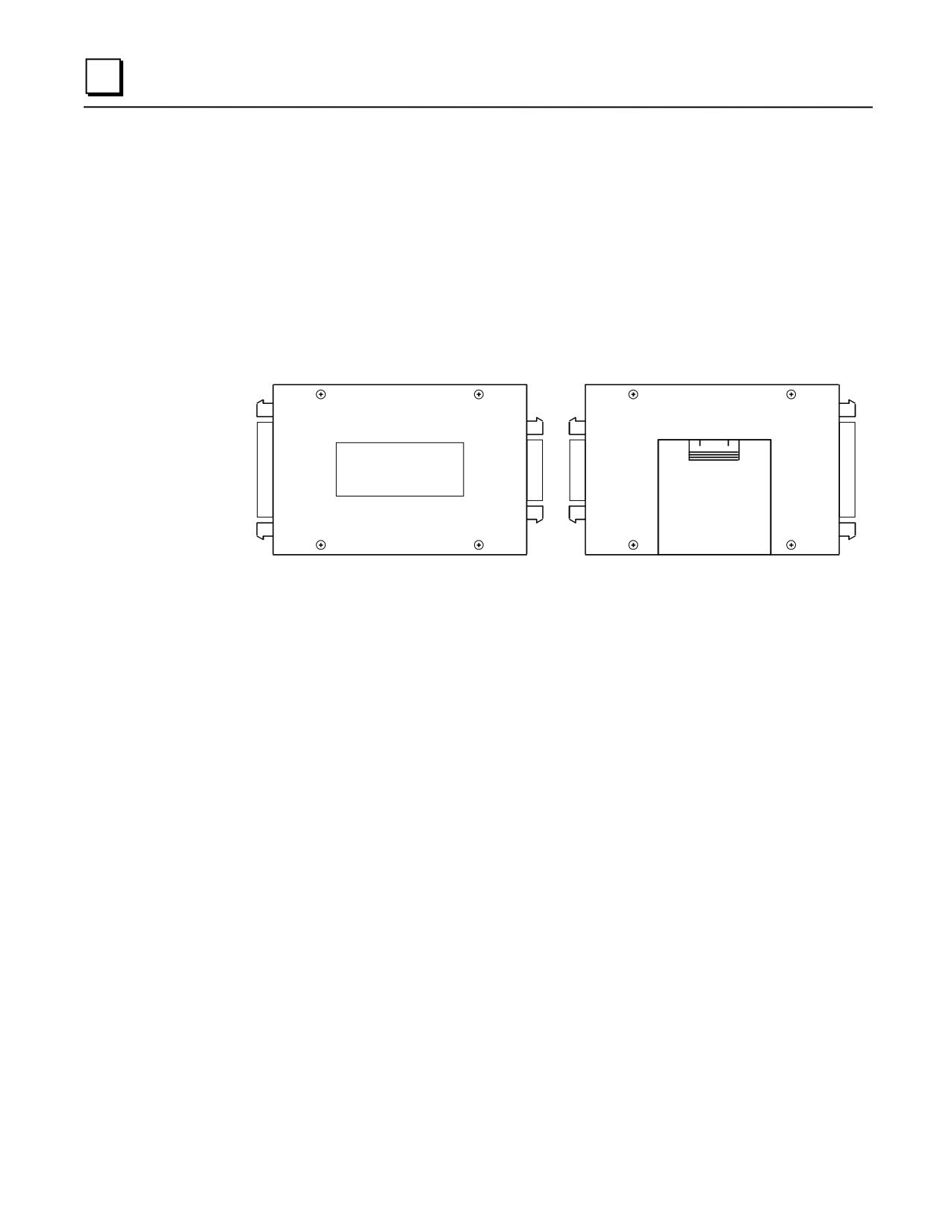
FRONT VIEW
REAR VIEW
GE Fanu c
IC690ACC900A
CABLE ADAPTER
MADE IN USA
Figure B-1. Front and Rear View of Converter
Installation
Installation of the RS-422/RS-485 to RS-232 Converter consists of connecting two cables. Select
the proper cables for your installation. Prewired cables (see below) are available from GE Fanuc,
or if cables of different lengths are required by your application, you can build your own cables.
Specifications for building these cables are provided later in this appendix.
You do not need to connect an external source of power to the converter for a cable length of 10
feet, or less, since the necessary power connections of +5 VDC and signal ground are derived from
the PLCs backplane bus through the cable which connects to the Series 90-30 or 90-70 PLC.
1.
Select one of the three RS-232 compatible cables (10 feet in length) that will connect the
programmer’s (or other serial device) RS-232 serial port to the RS-232 port on the converter.
The catalog numbers of these cables are: IC690CBL701 (use with Workmaster industrial
computer, or IBM PC-XT or compatible personal computer), IC690CBL702 (use with IBM
PC-AT or compatible personal computer), and IC690CBL705 (use with Workmaster II
industrial computer, or IBM PS/2 or compatible personal computer).
2.
A standard 6-foot cable (HHP compatible) is available to connect the RS-422/RS-485 port on
the converter to the RS-485 port on the Series 90-30 or Series 90-70 PLC. The catalog number
of this cable is IC693CBL303.
Installation of these cables should be done with the PLC powered-down.
• Connect the 25-pin male connector on the 10 foot cable to the 25-pin female connector on the
converter.
B-2
Series 90-30 PLC Installation and Hardware Manual - August 2002
GFK-0356Q
B
• Connect the female connector (9-pin or 25-pin) on the opposite end of this cable to the male
RS-232 connector (serial port) on the selected programming (or other serial) device. If you
build you own cable, use a connector that is compatible with your serial device.
• Notice that both ends of the 6-foot RS-422/RS-485 compatible cable are the same; a 15-pin
male connector is attached at both ends. Connect one end of this cable to the 15-pin female
connector on the RS-422/RS-485 connector on the converter.
• Connect the other end of this cable to the 15-pin female connector, which interfaces to the RS-
485 compatible serial port on the Series 90-30 or Series 90-70 PLC. For the Series 90-30 PLC,
this connector is accessed by opening the hinged door on the power supply. The serial port
connector for the Series 90-70 PLC is on the CPU module, and is accessed by opening the
hinged door on the module.
Cable Description
The serial connection to the Series 90-70 PLC (see Figure B-1) is to the RS-422/RS-485
compatible serial port connector, located at the bottom of the CPU module behind the hinged door,
through a 6 foot (2 meter) serial interface cable, IC693CBL303. Wiring information and
recommended cable and connectors are provided for those who may want to build their own cable
having a different length.
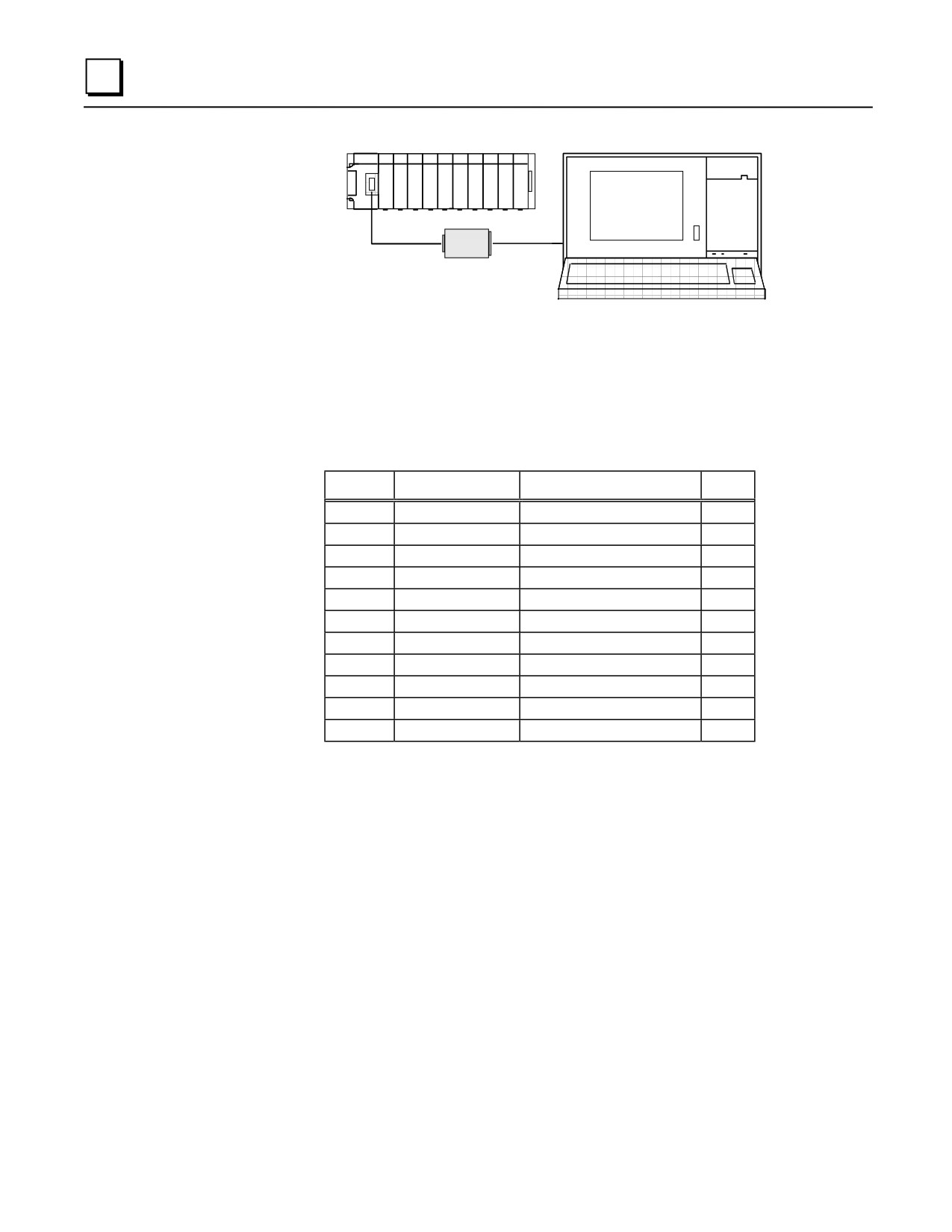
The serial connection to the Series 90-30 PLC is to the RS-485 compatible serial port connector
located behind the hinged door on the right front of the power supply, through the same 6 foot
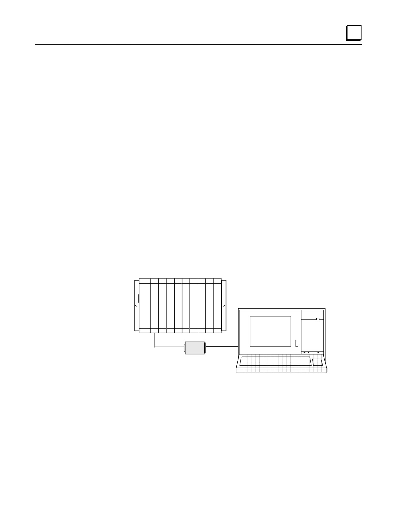
serial interface cable, IC693CBL303, or equivalent, Figure B-2).
SERIES 90-70
C
P
U
PROGRAMMER
RS-485
RS-232
CONVERTER
Figure B-2. Typical Configuration with Series 90-70 PLC
GFK-0356Q
Appendix B IC690ACC900 Converter
B-3
B
SERIES 90-30
PROGRAMMER
RS-485
RS-232
CONVERTER
Figure B-3. Typical Configuration with Series 90-30 PLC
RS-232 Interface Pin Assignments
Pin assignments and signal definitions for the RS-232 interface are listed below.
Table B-1. RS-232 Interface for Converter
Pin
Signal Name
Function
I/O
1
Shield
Cable shield
-
2
SD
Transmitted Data
Out
3
RD
Received Data
In
4
RTS
Request To Send
Out
5
CTS
Clear To Send
In
6
-
No connection
-
7
SG
Signal Ground
-
8
DCD
Data Carrier Detect
In
9/19
-
No connection
-
20
DTR
Data Terminal Ready
Out
21 to 25
-
No connection
-
B-4
Series 90-30 PLC Installation and Hardware Manual - August 2002
GFK-0356Q

B
RS-422/RS-485 Interface Pin Assignments
Pin assignments and signal definitions for the RS-422/RS-485 interface are listed below.
Table B-2. RS-422/RS-485 Interface for Converter
Pin
Signal Name
Function
I/O
1
Cable Shield
2
DCD(A)
Differential Data Carrier Detect
Out
3
DCD(B)
Differential Data Carrier Detect
Out
4
ATCH/
Attach (used with HHP)
n/a
5
+5 VDC
Logic Power
In
6
RTS(A)
Differential Request To Send
Out
7
SG
Signal Ground, 0V
In
8
CTS(B’)
Differential Clear To Send
In
9
RT
Resistor Terminator
n/a
10
RD(A’)
Differential Receive Data
In
11
RD(B’)
Differential Receive Data
In
12
SD(A)
Differential Send Data
Out
13
SD(B)
Differential Send Data
Out
14
RTS(B)
Differential Request To Send
Out
15
CTS(A’)
Differential Clear To Send
In
GFK-0356Q
Appendix B IC690ACC900 Converter
B-5
B
Logic Diagram
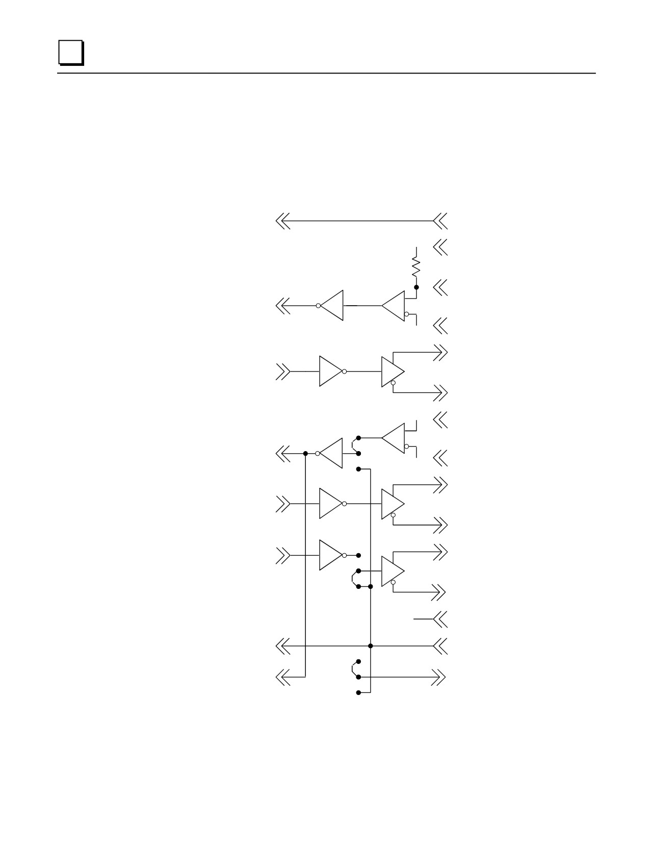
The following figure shows the logic diagram for the RS-422/RS-485 to RS-232 Converter.
RS-232/RS-485
a44539
CONVERTER
RS-232
RS-485
(IC690ACC900)
25-PIN
15-PIN
1
1
SHIELD
SHIELD
9
TERMINATOR
RESISTOR
120Ω
11
RD ( B' )
2
SD
10
RD ( A' )
13
SD (B )
3
RD
12
SD (A )
8
CTS ( B' )
MODEM
4
15
RTS
CTS ( A' )
14
RTS ( B )
5
CTS
6
RTS ( A )
DCD
3
8
DCD ( B )
DCD
2
DCD ( A )
LOGIC
5
+5
POWER
7
7
SG
SG
NC
20
4
DTR
ATTACH
ATCH/
Figure B-4. RS-422/RS-485 to RS-232 Converter Logic Diagram
B-6
Series 90-30 PLC Installation and Hardware Manual - August 2002
GFK-0356Q
B
Jumper Configuration
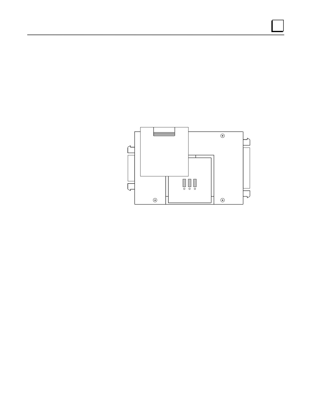
There are three jumper locations on the converter board for selection of user options. Each jumper
position has three pins, as shown in the following illustration. These jumper positions, labeled JP2,
JP3, and JP4, are accessed by removing the square plastic cover on the top of the converter.
Configuration can be changed as required by carefully removing one or more of the jumpers with a
pair of needle nose pliers and placing it on the desired pair of pins.
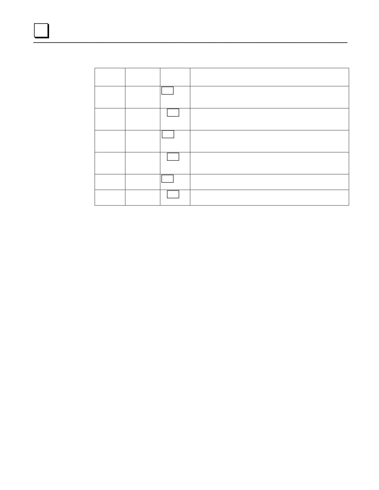
Refer to the description of these selectable jumper positions in the following table and place the
jumper on the selected pair of pins. The pin numbers are 1, 2, and 3. Default jumper locations are
indicated by a rectangle around the pins to be jumpered for each position. The default pin numbers
are 1 and 2.
RS-422/RS485
RS-232
1
2
3
Figure B-5. Location of Jumpers for User Options
GFK-0356Q
Appendix B IC690ACC900 Converter
B-7
B
Table B-3. Jumper Configuration for RS-422/RS-485 to RS-232 Converter
Jumper
Label
Jumper
Description*
Position
JP2
DCD
1 2
3
Default position 1 and 2 is used when the device communicating
with the PLC does not supply the Carrier Detect signal. JP2 forces
the DCD signal active on the RS-485 port.
1 2 3
Use jumper positions 2 and 3 if the device does supply the Carrier
Detect signal. This allows the programming device to control
DCD.
JP3
MODEM
1 2
3
Default position 1 and 2 is used when an attached Modem does not
require the Clear To Send (CTS) signal. This allows the
programming device to control the RTS signal.
1 2 3
Jumper positions 2 and 3 are used when the attached Modem does
require the CTS signal (most modems require this signal). Forces
RTS to be continually active.
JP4
ATTACH
1 2
3
Default position 1 and 2 is used for most applications
communicating with the PLC via a serial programming device.
1 2 3
Jumper positions 2 and 3 are used if the device communicating with
the PLC is intended to emulate the HHP protocol.
*Refer to the documentation for your serial device for signal requirements.
B-8
Series 90-30 PLC Installation and Hardware Manual - August 2002
GFK-0356Q