FANUC Series 0i-MODEL D, FANUC Series 0i Mate-MODEL D. MAINTENANCE MANUAL - page 12
8.DIGITAL SERVO
B-64305EN/03
(9) Reference counter
1821
Reference counter capacity for each axis (0 to 99999999)
(a) For the semi-closed loop
Reference counter
= Number of position pulses required per motor revolution or the same number divided by an integer
NOTE
If the rotation ratio between the motor and table is not an integer when a rotation
axis is used, a reference counter capacity needs to be set so that the point
where reference counter = 0 (grid point) always appears at the same position
relative to the table.
Example of setting)
αi Pulsecoder, semi-closed loop (1 μm detection)
Lead of ball screw
Required number of position pulses
Grid width
Reference counter
(mm/revolution)
(pulses/revolution)
(mm)
10
10000
10000
10
20
20000
20000
20
30
30000
30000
30
If there is an error between the required number of position pulses per motor revolution and the setting of
the reference counter, the reference position varies, depending on the start point.
Such an error needs to be eliminated by changing the detection unit. In this case, a reference counter
capacity may be set using a fraction.
Example of setting)
System with detection unit = 1 μm, ball screw lead = 20 mm/revolution, and deceleration ratio = 1/17
(i)
Method of setting a reference counter capacity as a fraction
Required number of position pulses per motor revolution = 20000/17
Set the following parameters:
1821
Reference counter capacity of each axis (numerator) (0 to 99999999)
2179
Reference counter capacity of each axis (denominator) (0 to 100)
The parameter for a denominator is not displayed on the servo setting screen. So, a denominator
needs to be set on the parameter screen.
In this example, set numerator = 20000, and denominator = 17.
NOTE
The reference counter assumes only an integer. So, if a fraction is set for a
reference counter capacity, the gap to the point where reference counter = 0 is
compensated for.
(In pulse control theory, a position less than one pulse cannot be controlled. So,
grid interval compensation is performed so that a grid point error is less than one
detection unit at all times.)
(ii) Method of changing the detection unit
Required number of position pulses per motor revolution = 20000/17
- 314 -
B-64305EN/03
8.DIGITAL SERVO
The values of all of the following parameters are multiplied by 17 to change the detection unit to
1/17 μm:
Parameter to be changed
FFG × 17
Can be changed on the servo setting screen.
CMR × 17
Can be changed on the servo setting screen.
Reference counter × 17
Can be changed on the servo setting screen.
Effective area × 17
No.1826, No.1827
Positional deviation limit value during movement × 17
No.1828
Positional deviation limit value during a stop × 17
No.1829
Backlash amount × 17
No.1851, No.1852
As the detection unit is changed from 1 μm to 1/17 μm, the values of all parameters to be set using
the detection unit must be multiplied by 17.
CAUTION
In addition to the parameters listed above, there are parameters to be set using
the detection unit.
For detailed descriptions, refer to [Unit of data] in each parameter description in
the Parameter Manual (B-64310EN).
This change eliminates an error between the required number of position pulses per motor revolution
and the reference counter.
Required number of position pulses per motor revolution = 20000
Reference counter = 20000
(b)
For the closed loop
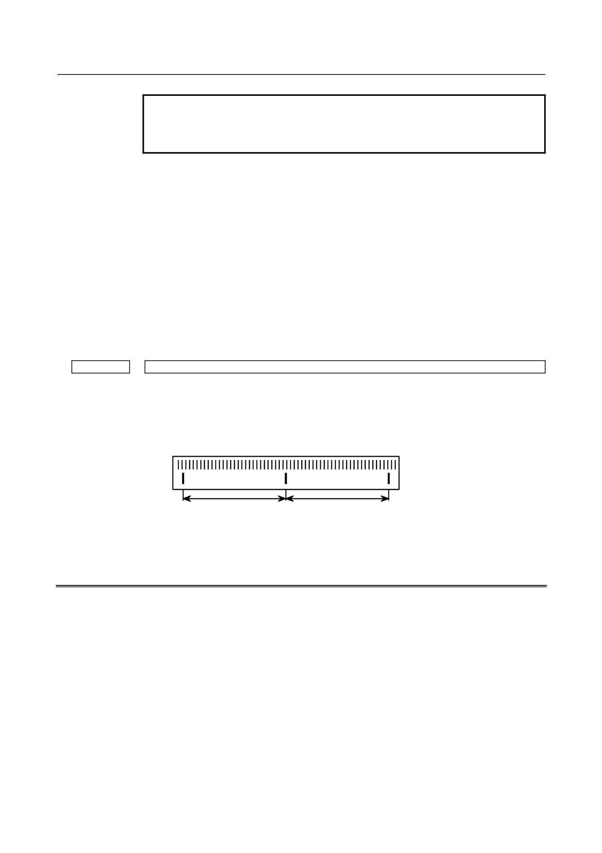
Reference counter = Z phase (reference position) interval/detection unit or the same number divided by an integer
If the reference counter does not assume an integer, see the example of semi-closed loop.
NOTE
If the rotation ratio between the separate detector and table is not an integer
when a rotation axis is used, a reference counter capacity needs to be set so
that the point where reference counter = 0 (grid point) always appears at the
same position relative to the table.
Example of setting)
Example 1)
When Z phase interval = 50 mm and detection unit = 1 μm
Reference counter = 50,000/1 = 50,000
Example 2)
When detection unit = 0.001° with a rotation axis
Reference counter = 360/0.001 = 360,000
Example 3)
When there is only one Z phase as in the case of a linear scale
Set a simple number such as 10000 and 50000 for the reference counter.
7.
Turn off the power then back on.
- 315 -
8.DIGITAL SERVO
B-64305EN/03
8.2
FSSB DISPLAY AND SETTING SCREEN
Connecting the CNC control unit to servo amplifiers via a high-speed serial bus (FANUC Serial Servo
Bus, or FSSB), which uses only one fiber optics cable, can significantly reduce the amount of cabling in
machine tool electrical sections.
Using the FSSB setting screen to specify axis-to-amp relationships enables axis settings to be calculated
automatically; that is, if bit 0 (DFS) of parameter No. 14476 = 0, parameters Nos. 1023, 1905, 1936, 1937,
14340 to 14349, and 14376 to 14391 are set automatically, and if bit 0 (DFS) of parameter No. 14476 = 1,
parameters Nos. 1023, 1905, 1910 to 1919, 1936, and 1937 are set automatically.
Display
The FSSB setting screen displays FSSB-based amplifier and axis information. This information can also
be specified by the operator.
1
Press function key
2
To display [FSSB], press continuous menu key
several times.
3
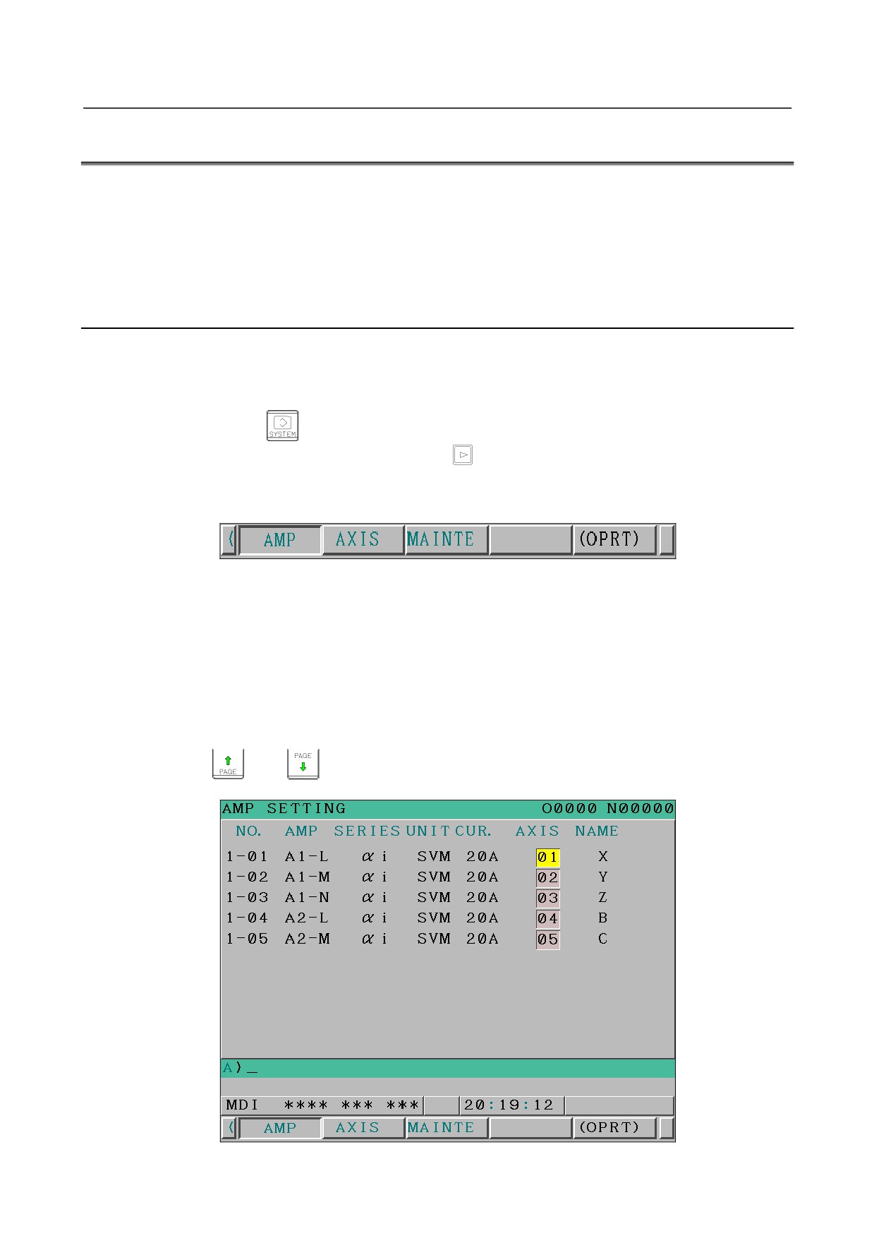
Pressing soft key [FSSB] causes the AMP SET screen (or the previously selected FSSB setting
screen) to appear, with the following soft keys displayed.
The FSSB setting screens include: AMP SET, AXIS SET, and AMP MAINTENANCE.
Pressing soft key [AMP] causes the AMP SET screen to appear.
Pressing soft key [AXIS] causes the AXIS SET screen to appear.
Pressing soft key [MAINTE] causes the AMP MAINTENANCE screen to appear.
<1> Amplifier setting screen
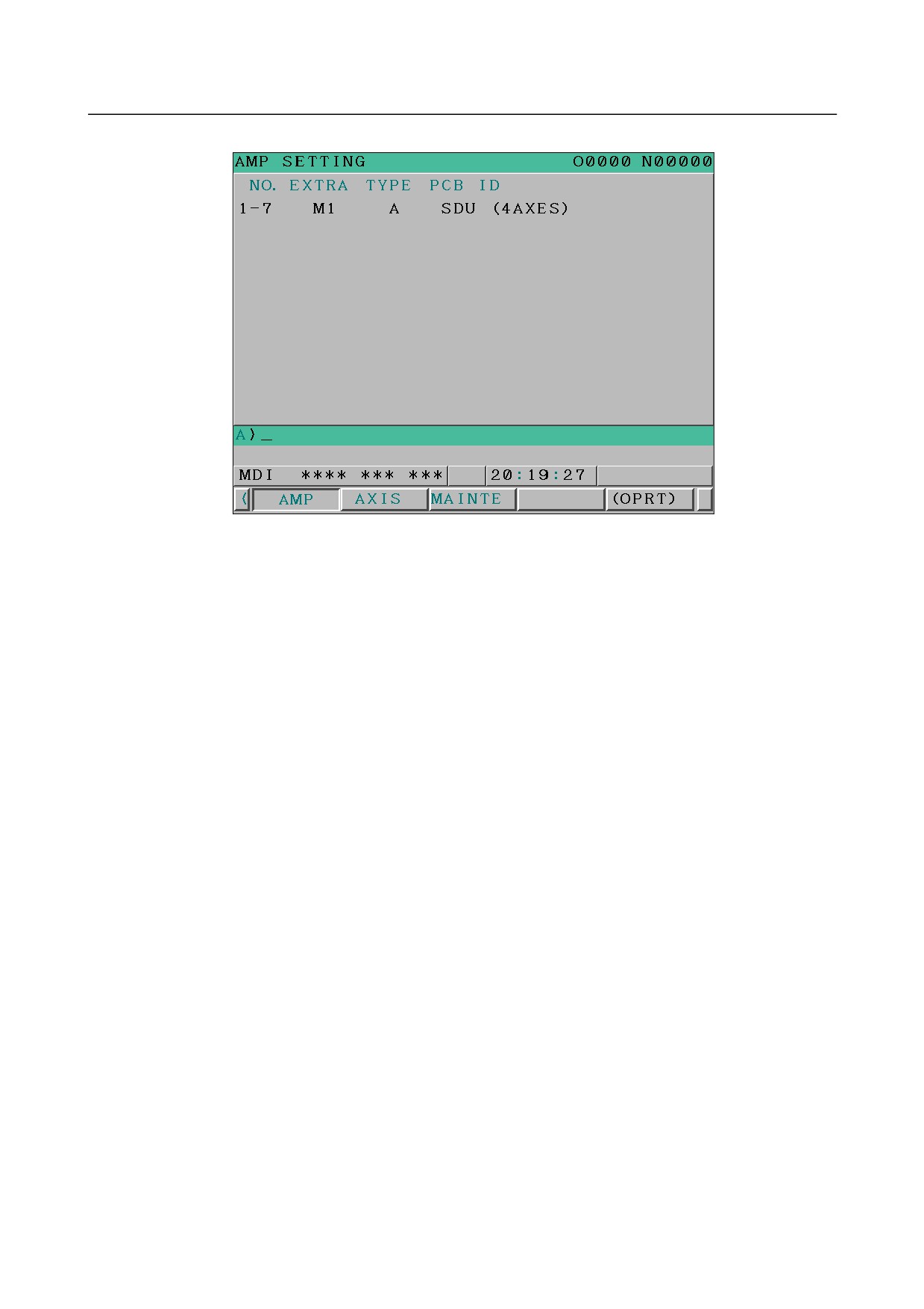
The amplifier setting screen consists of two sections: the first section displays information about the
slave, while the second section displays information about the separate detector interface units.
Page keys
and
can be used to switch between the sections.
- 316 -
B-64305EN/03
8.DIGITAL SERVO
The amplifier setting screen consists of the following items:
•
NO. (slave number)
For slaves connected by the FSSB, up to 10 continuous slave numbers (up to 8 for amps and up
to 2 for interface units) assigned with the one nearest to the CNC as the lowest slave number
are displayed.
Each slave number displayed on the amp setting screen consists of “1” indicating the FSSB1
line, "-" (hyphen) that follows it, and the slave unit number of the connected slave arranged in
ascending order with the one nearest to the CNC as the lowest number.
•
AMP (amplifier type)
The amplifier type display consists of the letter A, which stands for "amplifier," a number that
indicates the placing of the amplifier, as counted from that nearest to the CNC, and a letter such
as L (first axis), M (second axis), or N (third axis) indicating the placing of the axis in the
amplifier.
•
AXIS NO. (controlled axis number)
Each controlled axis number displayed is a value set in parameter Nos. 14340 to 14349 plus 1 if
bit 0 (DFS) of parameter No. 14476 = 0 or a value set in parameter Nos. 1910 to 1919 plus 1 if
bit 0 (DFS) of parameter No. 14476 = 1.
•
NAME (controlled axis name)
The axis name assigned to a parameter (No. 1020) corresponding to a particular controlled axis
number is displayed. If the controlled axis number is 0, - is displayed.
•
The following items are displayed as amplifier information:
-
SERIES (servo amplifier name)
-
UNIT (servo amplifier unit type)
-
CURRENT (maximum rating)
•
The following items are displayed as separate detector interface unit information:
-
SEPARATE
This display consists of the letter M, which stands for "separate detector interface unit"
and a number indicating the placing of the pulse module, as counted from that nearest to
the CNC.
-
TYPE
This display is a letter indicating the type of the separate detector interface unit.
- 317 -
8.DIGITAL SERVO
B-64305EN/03
-
PCB ID
This display consists of four digits indicating the separate detector interface unit ID
(hexadecimal). The separate detector interface unit ID is followed by SDU (8-AXES) for
the eight-axis separate detector module or SDU (4-AXES) for the four-axis separate
detector module.
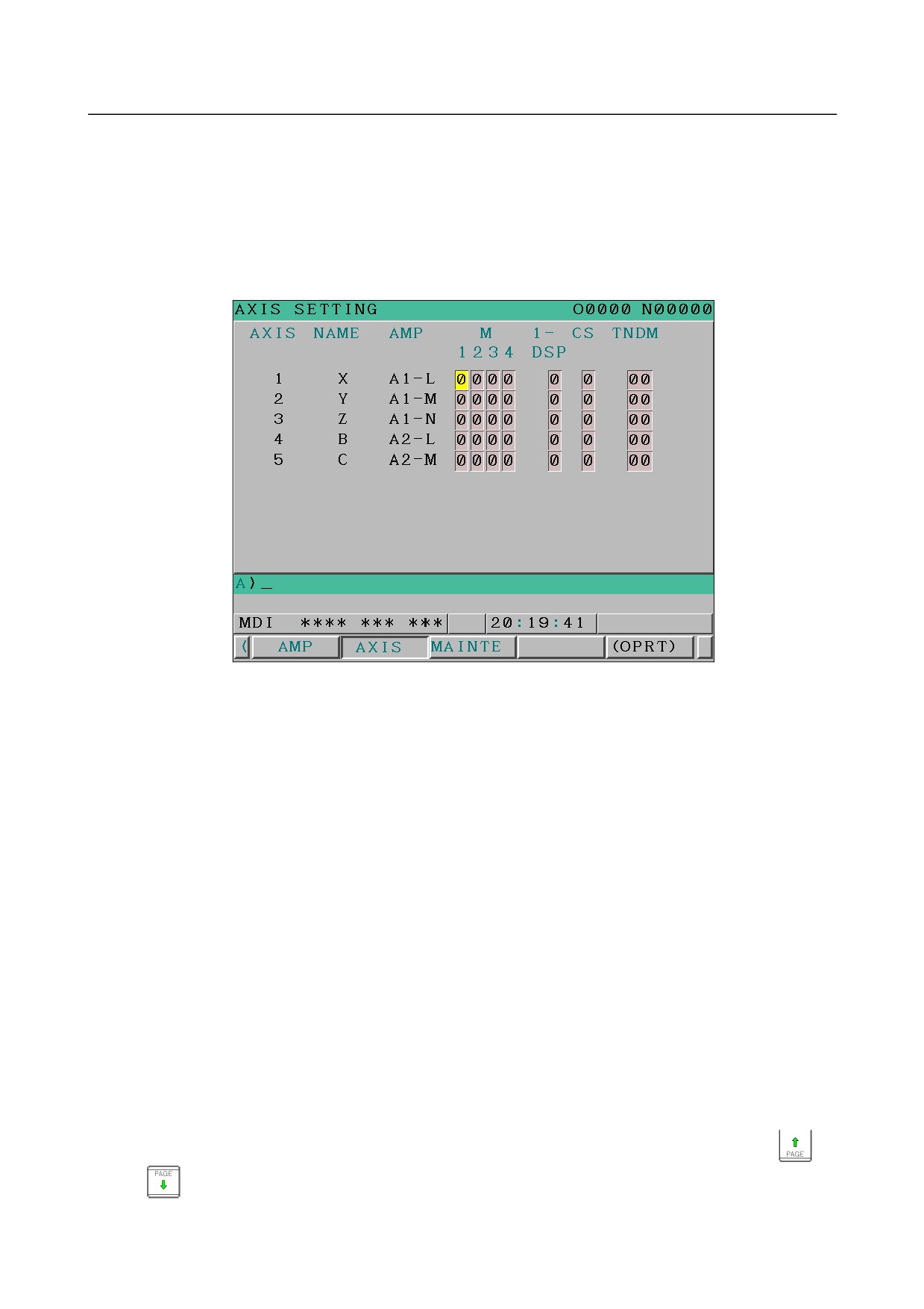
<2> Axis setting screen
The axis setting screen displays the information shown below:
This axis setting screen displays the following items:
•
AXIS (controlled axis number)
This item is the placing of the NC controlled axis.
•
NAME (controlled axis name)
•
AMP (type of the amplifier connected to each axis)
•
M1 (connector number for separate detector interface unit 1)
The connector number for separate detector interface unit 1 stored in the SRAM is displayed.
•
M2 (connector number for separate detector interface unit 2)
The connector number for separate detector interface unit 2 stored in the SRAM is displayed.
•
1-DSP
If the number of servo HRV3 controlled axes that can be controlled by one DSP is limited, the
number of axes controllable by one DSP stored in the SRAM is displayed. When 0 is displayed,
no limitation is imposed.
•
Cs (Cs contour controlled axis)
The value stored in the SRAM is displayed. It is spindle number for the Cs contour controlled
axis.
•
TNDM
The value stored in the SRAM is displayed. Consecutive odd and even numbers are displayed
for the master and slave axes for tandem control.
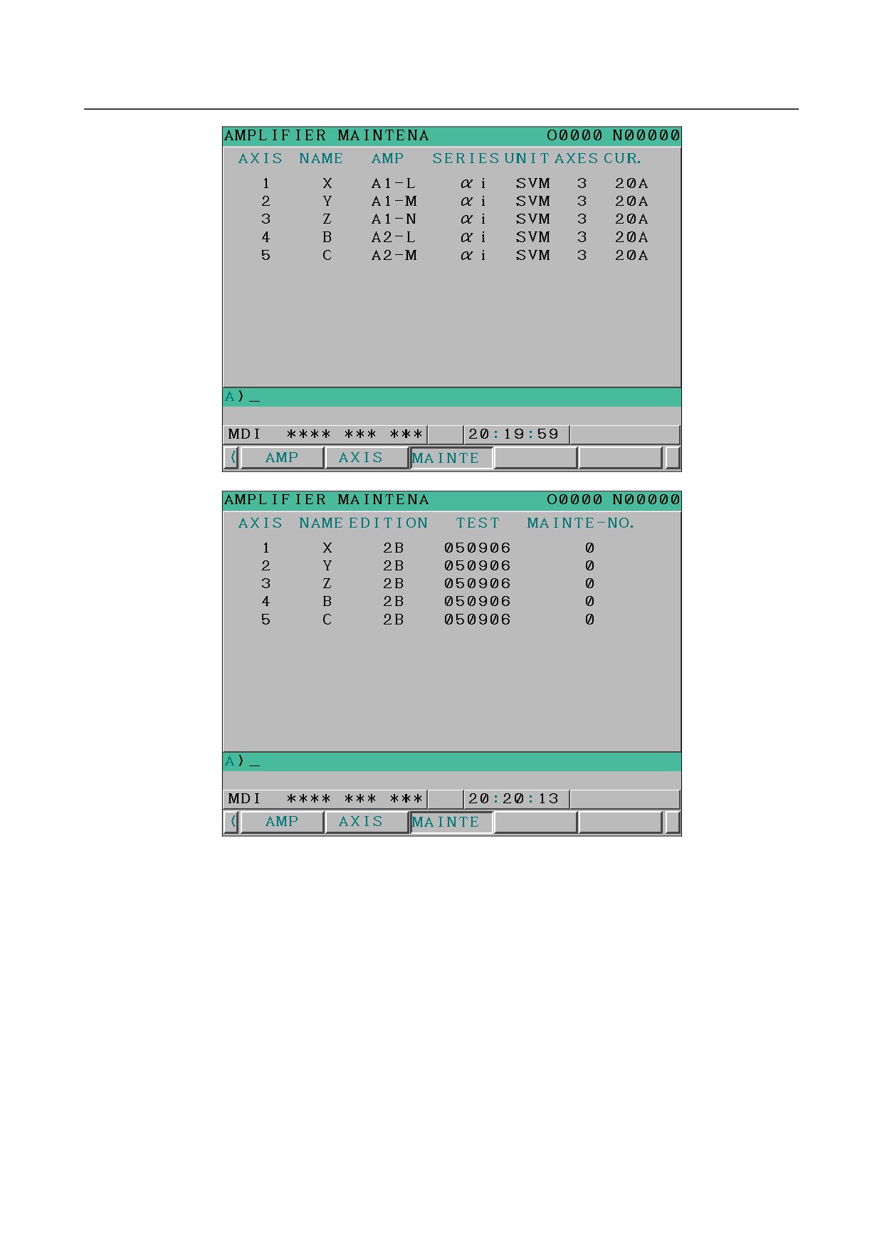
<3> Amplifier maintenance screen
The amplifier maintenance screen displays maintenance information for servo amplifiers. This
screen consists of the following two pages, either of which can be selected by pressing the
or
key.
- 318 -
B-64305EN/03
8.DIGITAL SERVO
The amplifier maintenance screen displays the following items:
•
AXIS (controlled axis number)
•
NAME (controlled axis name)
•
AMP (type of amplifier connected to each axis)
•
SERIES (servo amplifier series of an amplifier connected to each axis)
•
UNIT (unit type of a servo amplifier connected to each axis)
•
AXES (maximum number of axes controlled by an amplifier connected to each axis)
•
CUR. (maximum rating for amplifiers connected to each axis)
•
EDITION (unit version number of an amplifier connected to each axis)
•
TEST (date of test performed on an amplifier connected to each axis)
Example) 090123 = January 23, 2009
•
MAINTE-NO. (engineering change number for an amplifier connected to each axis)
- 319 -
8.DIGITAL SERVO
B-64305EN/03
Setting
On an FSSB setting screen (other than the amplifier maintenance screen), pressing soft key [(OPRT)]
displays the following operation selection soft keys:
To enter data, place the machine in MDI mode or the emergency stop state, position the cursor to the
point where a desired item is to be input, then enter the desired data and press soft key [INPUT] (or the
key on the MDI panel).
When soft key [SETING] is pressed after data is entered, a warning message is displayed if the entered
data is incorrect. When the entered data is correct, it is set in parameters Nos. 1023, 1905, 1936, 1937,
14340 to 14349, and 14376 to 14391 if bit 0 (DFS) of parameter No. 14476 = 0 or parameter Nos. 1023,
1905, 1910 to 1919, 1936, and 1937 if bit 0 (DFS) of parameter No. 14476 = 1.
To restore the previous value of a parameter if, for example, an entered value is incorrect, press soft key
[CANCEL].
When the power is turned on, values are read from the parameters and displayed on the screen.
CAUTION
1 For the parameters to be specified on the FSSB setting screen, do not attempt to
enter values on the parameter screen using the MDI or a G10 command. Use
only the FSSB screen to enter values for these parameters.
2 If pressing soft key [SETING] results in a warning being issued, re-enter the data
or press soft key [CANCEL] to reset the warning. Pressing the reset key cannot
reset the warning.
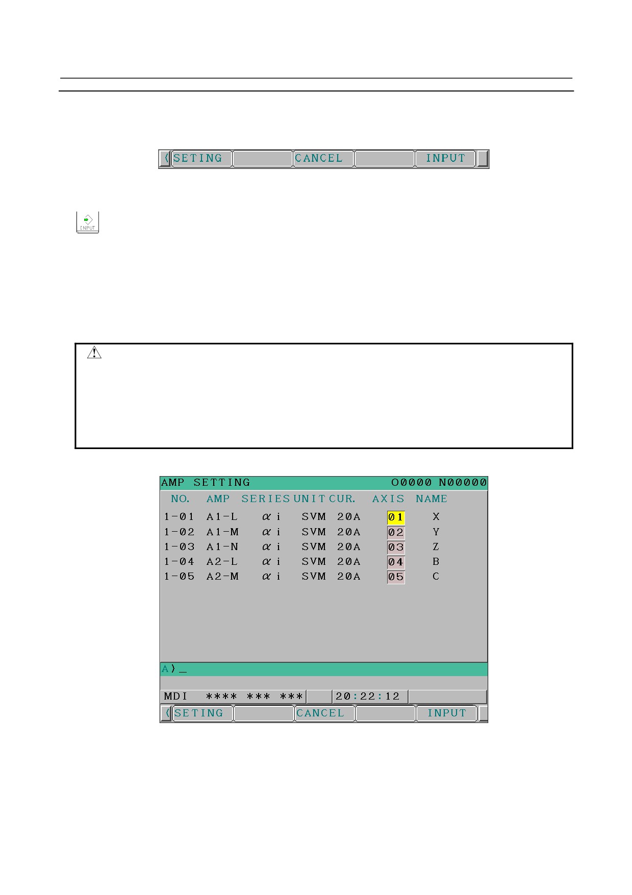
<1> Amplifier setting screen
The amplifier setting screen displays the following items:
•
NO. (controlled axis number)
For this item, enter a value of between 1 and the maximum number of controlled axes. If a
number that falls outside this range is entered, the warning message "INVALID FORMAT"
appears. If the entered controlled axis number is duplicate or
0, the warning message
"SPECIFIED DATA IS OUT OF RANGE" appears when soft key [SETING] is pressed to
assert the entered value. In this case, no value can be entered for the parameter.
- 320 -
B-64305EN/03
8.DIGITAL SERVO
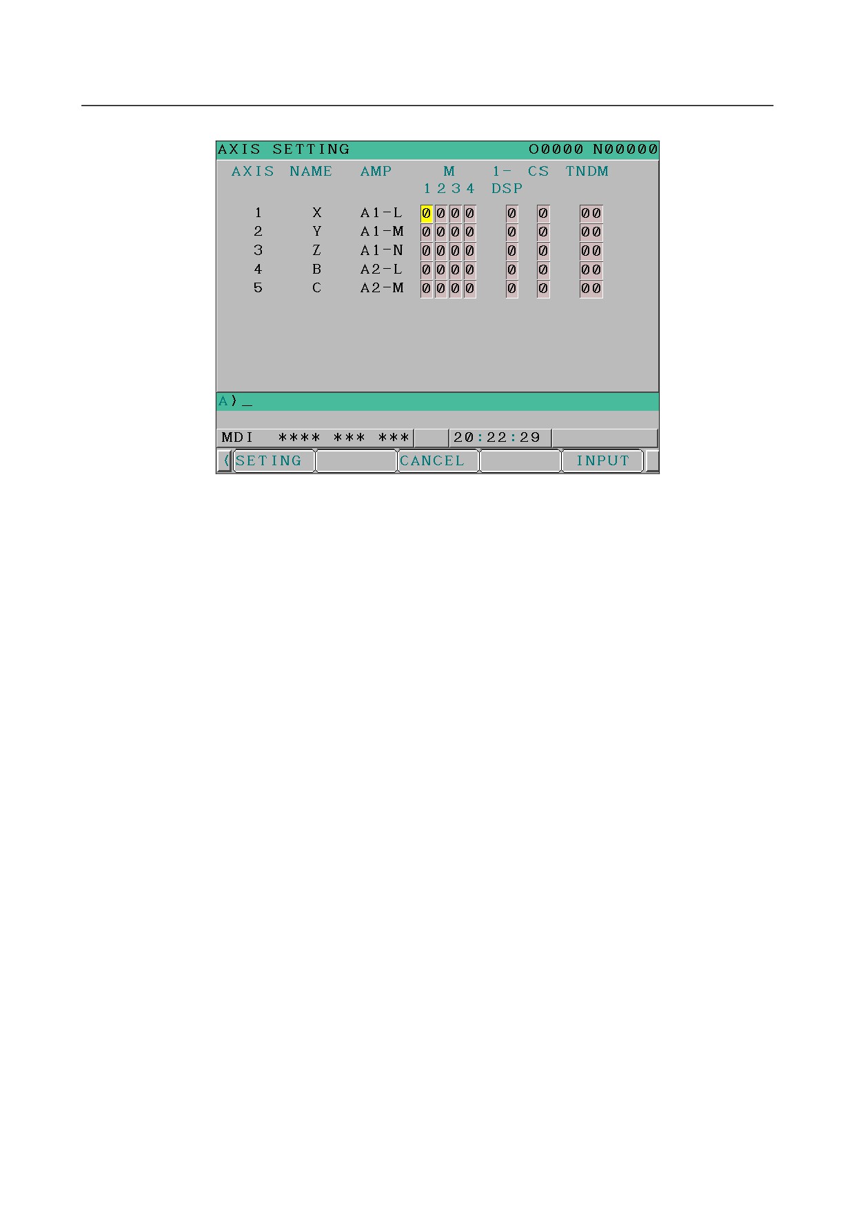
<2> Axis setting screen
On the axis setting screen, the following items can be specified:
•
M1 (connector number for separate detector interface unit 1)
M2 (connector number for separate detector interface unit 2)
For an axis on which to use each separate detector interface unit, enter a connector number with
a number 1 to 8 (maximum number of connectors on a separate detector interface unit).
When a separate detector interface unit is not connected and a number that falls outside the
valid range is entered, the warning message
“ILLEGAL DATA” is displayed. When a
separate detector interface unit is connected and a number that falls outside the valid range is
entered, the warning message “DATA IS OUT OF RANGE” is displayed.
•
1-DSP
If the number of servo HRV3 controlled axes that can be controlled by one DSP is limited, set
the number of axes controllable by one DSP.
Number of servo HRV3 controlled axes
Setting: 3
The same value is set for axes other than Cs contour controlled axes.
If a value other than 0, 1, and 3 is input, the warning "INVALID FORMAT" is output.
•
Cs (Cs contour controlled axis)
Enter spindle number (1 to 2) for the Cs contour controlled axis. If a number other than 0 to 2 is
entered, the warning message “DATA IS OUT OF RANGE” is displayed.
•
TNDM (or M/S if EGB (T series) is enabled)
Enter odd and even numbers for axes for tandem control or EGB (T series). These numbers
must be consecutive and within a range between 1 and the number of controlled axes. If a
number that falls outside the valid range is entered, the warning message “DATA IS OUT OF
RANGE” is displayed.
When soft key [SETING] is pressed on the axis setting screen after data entry, the warning message
“DATA IS OUT OF RANGE” is displayed if any of the following conditions is satisfied.
•
The setting disables the connection of controlled axes with amplifiers and separate detector
interface units.
•
A value other than 0 is specified for both M1 and M2 for an axis.
•
A value other than 0 is specified for both Cs and TNDM for an axis.
•
1-DSP is 1 and TNDM is not 0 for an axis.
•
1-DSP is 3 and TNDM is specified for a multiple of four for an axis.
•
A duplicate value is specified for M1.
•
A duplicate value is specified for M2.
•
A duplicate value is specified for Cs.
- 321 -
8.DIGITAL SERVO
B-64305EN/03
•
A duplicate value is specified for TNDM.
•
An invalid master/slave axis pair is specified for TNDM.
8.3
SERVO TUNING SCREEN
8.3.1
Parameter Setting
Set a parameter to display the servo tuning screen.
#7
#6
#5
#4
#3
#2
#1
#0
3111
SVS
[Input type] Setting input
[Data type] Bit path
#0 SVS Servo setting screen or servo tuning screen is:
0: Not displayed.
1: Displayed.
8.3.2
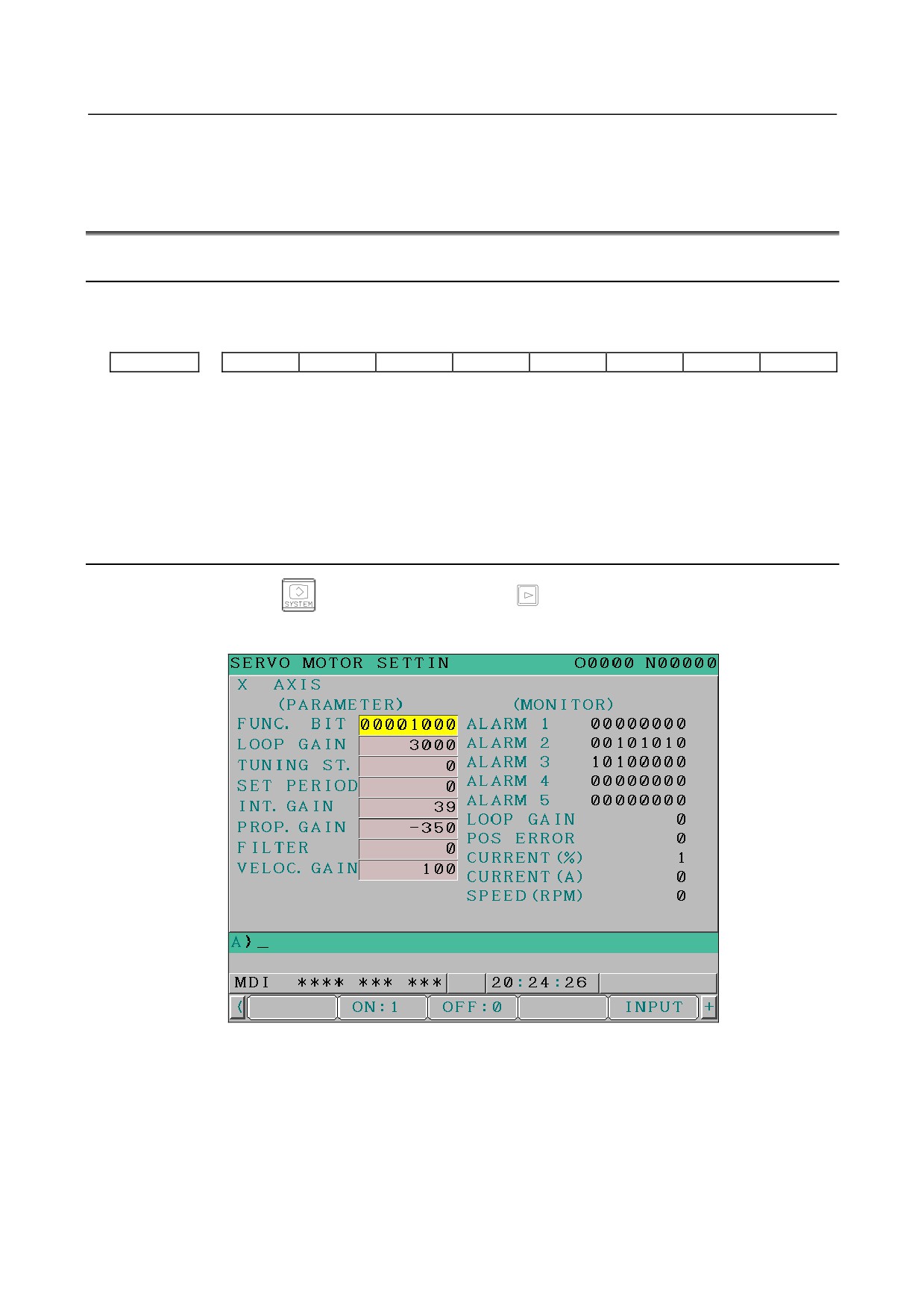
Displaying Servo Tuning Screen
1
Press function key
key, continuous menu key
, and soft key [SV.SET] in this order.
2
Press soft key [SV.TUN] to select the servo tuning screen.
<1>
<9>
<2>
<10>
<3>
<11>
<12>
<4>
<13>
<5>
<14>
<6>
<15>
<7>
<16>
<8>
<17>
<18>
- 322 -
B-64305EN/03
8.DIGITAL SERVO
(1) Function bit : Parameter No.2003
(2) Loop gain : Parameter No.1825
(3) Tuning start :
(4) Set period :
(5) Integral gain : Parameter No.2043
(6) Proportional gain : Parameter No.2044
(7) Filter : Parameter No.2067
(8) Velocity gain Set value(Parameter No.2021)+256
×100
256
(9) Alarm 1 : Diagnosis No.200
(10) Alarm 2 : Diagnosis No.201
(11) Alarm 3 : Diagnosis No.202
(12) Alarm 4 : Diagnosis No.203
(13) Alarm 5 : Diagnosis No.204
(14) Loop gain : Actual loop gain
(15) Position error : Actual position error (Diagnosis No.300)
(16) Current(%) : Indicate current with % to the rated value.
(17) Current(A) : Indicate current with A (peak value).
(18) Speed RPM : Number of motor actual rotation
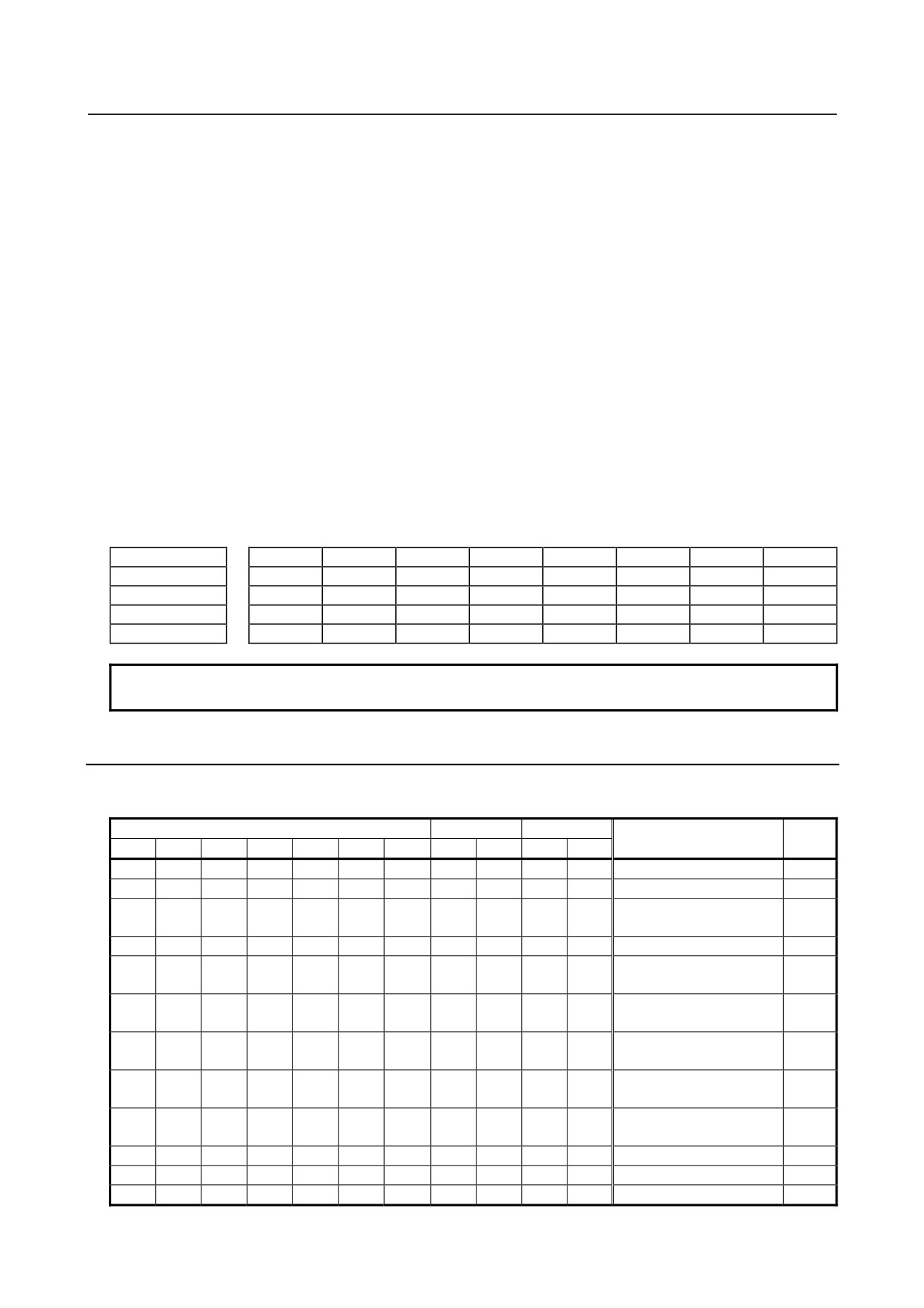
#7
#6
#5
#4
#3
#2
#1
#0
Alarm 1
OVL
LVA
OVC
HCA
HVA
DCA
FBA
OFA
Alarm 2
ALD
EXP
Alarm 3
CSA
BLA
PHA
RCA
BZA
CKA
SPH
Alarm 4
DTE
CRC
STB
PRM
Alarm 5
OFS
MCC
LDM
PMS
FAN
DAL
ABF
NOTE
The empty fields do not represent alarm codes.
8.3.3
Alarms Related to Amplifiers and Motors
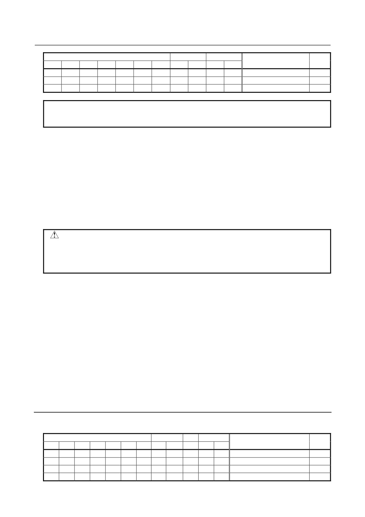
An alarm is identified from the data of alarms 1, 2, and 5. The meaning of each bit is indicated below.
Alarm 1
Alarm 5
Alarm 2
Description
Action
OVL
LVA
OVC
HCA
HVA
DCA
FBA
MCC
FAN
ALD
EXP
1
0
0
Overcurrent alarm (PSM)
1
0
1
Overcurrent alarm (SVM)
1
1
0
1
Overcurrent alarm
1
(software)
1
Overvoltage alarm
1
Excessive regenerative
discharge alarm
1
0
0
Power supply
undervoltage (PSM)
1
1
0
DC link undervoltage
(PSM)
1
0
1
Control power supply
undervoltage (SVM)
1
1
1
DC link undervoltage
(SVM)
1
0
0
Overheat (PSM)
2
1
1
0
Motor overheat
2
1
MCC welding, precharge
- 323 -
8.DIGITAL SERVO
B-64305EN/03
Alarm 1
Alarm 5
Alarm 2
Description
Action
OVL
LVA
OVC
HCA
HVA
DCA
FBA
MCC
FAN
ALD
EXP
1
0
0
Fan stop (PSM)
1
0
1
Fan stop (SVM)
1
OVC alarm
3
NOTE
For the alarms with no action number, see the maintenance manual of the servo
amplifier.
Action 1: Related to overcurrent alarms
An overcurrent alarm is issued when an excessively large current flows in the main circuit.
If an overcurrent alarm is always issued after the emergency stop state is canceled or at the time of
gradual acceleration/ deceleration, the cause may be a defective amplifier, cable connection error,
broken cable, or parameter setting error.
First, check if the servo parameters indicated below are set to the standard values. If the servo
parameters Nos. 2004, 2040, and 2041 are set to the standard values, check the amplifier and cable
connections according to the maintenance manual of the amplifier.
If an overcurrent alarm is issued only at the time of abrupt acceleration/deceleration, the use
condition is too severe. Increase the time constant and see what happens.
CAUTION
If the emergency stop state is canceled when the power line to the motor is
disconnected, an overcurrent alarm (software) may be issued. If this poses a
problem, set the following parameter to 1:
Bit 0 of parameter No. 2207: Ignores an overcurrent alarm (software).
Action 2: Related to overheat alarms
If an overheat alarm is issued after a long-time continuous operation, the temperature of the motor or
amplifier may be high. Stop the operation for a while and see what happens. If an overheat alarm is
still issued about 10 minutes after the power is turned off, the hardware is probably faulty.
If an overheat alarm is issued intermittently, increase the time constant or increase stop times in the
program to suppress an increase in temperature.
Action 3: Related to an OVC alarm
If an OVC alarm is issued, check if the parameters indicated below are set to the standard values.
No.1877, No.1878, No.1893
No.2062, No.2063, No.2065
No.2161, No.2162, No.2163, No.2164
If the parameters are set to the standard values, increase the time constant or increase stop times in
the program to suppress an increase in temperature.
8.3.4
Alarms related to the αi Pulsecoder
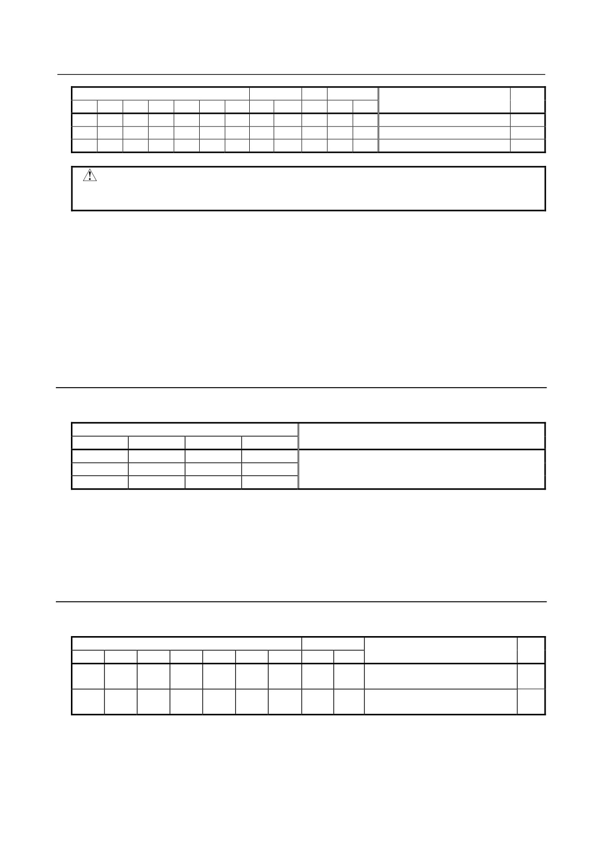
An alarm is identified from the data of alarms 1, 2, 3, and 5. The meaning of each bit is indicated below.
Alarm 3
Alarm 5
1
Alarm 2
Description
Action
CSA
BLA
PHA
RCA
BZA
CKA
SPH
LDM
PMS
FBA
ALD
EXP
1
Soft phase alarm
2
1
Battery voltage zero
1
1
1
1
0
Count error alarm
2
1
EEPROM error alarm
- 324 -
B-64305EN/03
8.DIGITAL SERVO
Alarm 3
Alarm 5
1
Alarm 2
Description
Action
CSA
BLA
PHA
RCA
BZA
CKA
SPH
LDM
PMS
FBA
ALD
EXP
1
Battery undervoltage (warning)
1
1
Pulse error alarm
1
LED error alarm
CAUTION
The alarms with no action number are considered to be caused by a Pulsecoder
failure. Replace the Pulsecoder.
Action 1: Battery-related alarms
Check if a battery is connected. When the power is turned on for the first time after a battery is
connected, a battery voltage zero alarm is issued. In such a case, turn off the power then turn on the
power again. If a battery voltage zero alarm is still issued, check the battery voltage. If a battery
undervoltage alarm is issued, check the voltage and replace the battery.
Action 2: Alarms that may be caused by noise
If an alarm is issued intermittently or an alarm is issued after the emergency stop state is canceled,
the cause of the alarm is probably noise. In this case, provide sufficient noise protection. If an alarm
is issued even after noise protection is provided, replace the Pulsecoder.
8.3.5
Alarms Related to Serial Pulsecoder Communication
An alarm is identified from the data of alarm 4. The meaning of each bit is indicated below.
Alarm 4
Description
DTE
CRC
STB
PRM
1
1
Serial Pulsecoder communication alarm
1
Action:
An error occurred in serial communication. Check if the cable is connected correctly and also check
if the cable is not disconnected and broken. If CRC or STB is 1, it is likely that the cause is noise.
Take an antinoise measure. If an alarm is always issued after the power is turned on, the Pulsecoder
or amplifier control board may be faulty.
8.3.6
Alarms Related to Disconnection
An alarm is identified from the data of alarms 1 and 2. The meaning of each bit is indicated below.
Alarm 1
Alarm 2
Actio
Description
OVL
LVA
OVC
HCA
HVA
DCA
FBA
ALD
EXP
n
Hard disconnection (separate A/B
1
1
1
1
phase disconnection)
Soft disconnection
1
0
0
2
(closed loop / αi Pulsecoder)
Action 1:
This alarm is issued when a separate A/B phase scale is used. Check if the A/B phase detector is
connected correctly.
- 325 -
8.DIGITAL SERVO
B-64305EN/03
Action 2: Full-closed
This alarm is issued when the position feedback pulse change is smaller than the velocity feedback
pulse change. This means that this alarm is not issued in a semi-closed loop. Check if the separate
detector outputs position feedback pulses correctly. If the separate detector outputs position
feedback pulses correctly, such a situation that only the motor makes turns in the reverse direction at
the start of machine movement because of a large backlash between the motor position and scale
position is considered to have occurred.
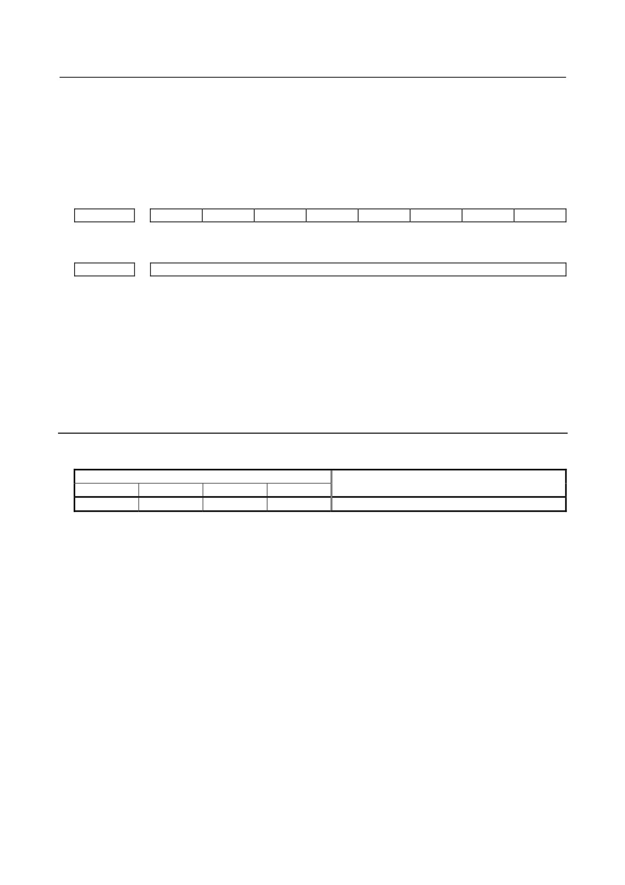
#7
#6
#5
#4
#3
#2
#1
#0
2003
TGAL
#1 TGAL 1: The parameter-set detection level is used for a soft disconnection alarm.
2064
Soft disconnection alarm level
Standard setting 4: An alarm is issued when the motor makes a 1/8 revolution.
Increase the setting of this parameter.
Action 2: αi Pulsecoder
This alarm is issued when synchronization between phase data and absolute position data sent from
the built-in Pulsecoder is lost. While the power to the NC is turned off, unplug the Pulsecoder cable,
then plug the cable once again after about 10 minutes. If this alarm is still issued, replace the
Pulsecoder.
8.3.7
Alarm Related to Invalid Parameter Settings
An alarm is identified from the data of alarm 4. The meaning of the PRM bit is defined as follows:
Alarm 4
Description
DTER
CRC
STB
PRM
1
Invalid parameter detected by the servo software
When PRM = 1, an invalid parameter is detected by the servo software. Read the value indicated by
diagnosis 352, and troubleshoot according to "FANUC AC SERVO MOTOR αis/αi series Parameter
Manual (B-65270EN)".
When PRM = 0, read the bit value indicated by diagnosis 280, and determine the cause according to the
following:
Diagnosis 280#0 = 1
: In parameter No. 2020 used for motor module specification, a value not within
the specifiable range is specified.
Diagnosis 280#2 = 1
: In parameter No. 2023, an incorrect value such as a value equal to or less than 0
is set.
Diagnosis 280#3 = 1
: In parameter No. 2024, an incorrect value such as a value equal to or less than 0
is set.
Diagnosis 280#4 = 1
: In parameter No. 2022, a correct value (111 or -111) is not set.
Diagnosis 280#6 = 1
: In parameter No. 2023, an incorrect value is set.
- 326 -
B-64305EN/03
8.DIGITAL SERVO
8.3.8
Others
An alarm is identified from the data of alarm 5. The meaning of each bit is indicated below.
Alarm 5
Description
Action
OFS
MCC
LDM
PMS
FAN
DAL
ABF
1
Feedback mismatch alarm
1
1
Semi-closed/closed loop excessive error alarm
2
1
Current offset error alarm
3
Action 1:
This alarm is issued when the move direction of the position detector becomes opposite to the move
direction of the speed detector. Check the rotation direction of the separate detector. If the rotation
direction of the separate detector is opposite to the rotation direction of the motor, take the following
action:
For the A/B phase detector:
Exchange the connections of A and A with each other.
For the serial detector:
Reverse the following signal direction setting for the separate detector.
Even with the A/B phase detector, the signal direction can be reversed by setting the parameter
below. This method cannot be used when absolute position communication is required.
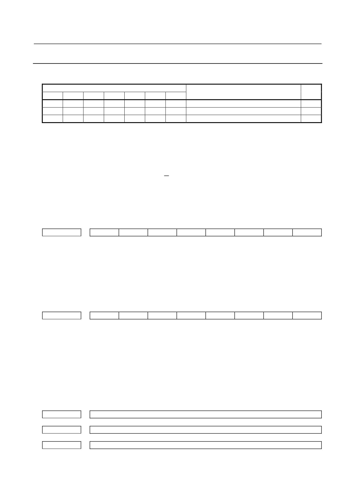
#7
#6
#5
#4
#3
#2
#1
#0
2018
RVRSE
#0 RVRSE Whether to reverse the signal direction of the separate detector can be set.
0: Does not reverse the signal direction of the separate detector.
1: Reverses the signal direction of the separate detector.
If there is a large distortion between the motor and separate detector, it is likely that the signal direction
may be reversed when the motor accelerates or decelerates steeply. In such a case, change the detection
level.
#7
#6
#5
#4
#3
#2
#1
#0
2018
RNLV
#1 RNLV The detection level of a feedback mismatch alarm can be changed.
0: Detected at 600 mm-1 or more
1: Detected at 1000 min-1 or more
Action 2:
This alarm is issued when the difference between the motor position and separate detector position
exceeds the semi-closed/closed loop excessive error level. Check if the dual position feedback
conversion coefficient is set correctly. If the dual position feedback conversion coefficient is set
correctly, increase the alarm level. If this alarm is still issued after changing the level, check the
connection direction of the scale.
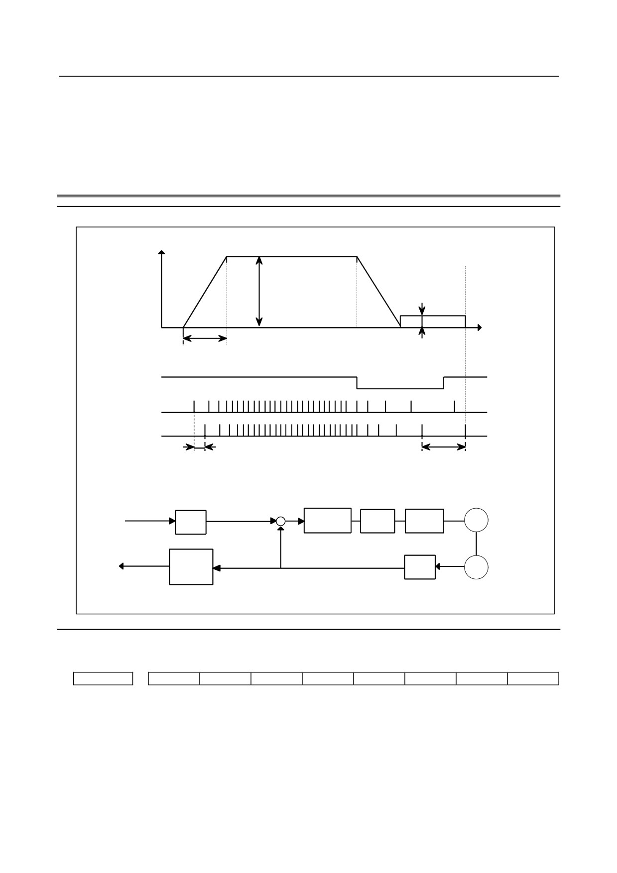
2078
Dual position feedback conversion coefficient (numerator)
2079
Dual position feedback conversion coefficient (denominator)
2118
Dual position feedback semi-closed/full-closed loop error level
[Setting] Detection unit. When 0 is set, no detection operation is performed.
- 327 -
8.DIGITAL SERVO
B-64305EN/03
Action 3:
The current offset value (equivalent to the current value during an emergency stop) of the current
detector becomes abnormally high. If this alarm is still issued after the power is turned off then back
on, the current detector is considered to be faulty. When using the αi series, replace the amplifier.
8.4
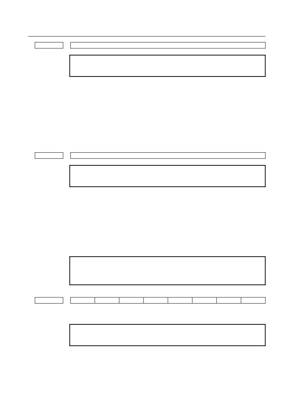
ADJUSTING REFERENCE POSITION (DOG METHOD)
Overview
Speed
Rapid traverse
FL rate
(Parameter No. 1420)
(Parameter No. 1425)
Time
Rapid traverse acc./dec. time constant (Parameter No. 1620)
*DECn
PCZ
Grid
Grid shift amount
Reference counter capacity
(Parameter No. 1850)
(Parameter No. 1821)
10mm/rev
10000P
Error
Proportion
Speed
M
CMR
counter
gain
Command
+
loop
-
×4
(Serial)
Reference
F⋅FG
PC
counter
GRID
10000P/rev (Flexible feed gear)
Counter capacity
10000P
Parameter
There are the following related parameters.
#7
#6
#5
#4
#3
#2
#1
#0
1005
DLZx
[Input type] Parameter input
[Data type] Bit axis
# 1 DLZx Function for setting the reference position without dogs
0: Disabled
1: Enabled
- 328 -
B-64305EN/03
8.DIGITAL SERVO
1821
Reference counter size for each axis
NOTE
When this parameter is set, the power must be turned off before
operation is continued.
[Input type] Parameter input
[Data type] 2-word axis
[Unit of data] Detection unit
[Valid data range] 0 to 999999999
Set a reference counter size.
As a reference counter size, specify a grid interval for reference position return based on
the grid method.
When a value less than 0 is set, the specification of 10000 is assumed.
When a linear scale with absolute address reference marks is used, set the interval of
mark 1.
1850
Grid shift and reference position shift for each axis
NOTE
When this parameter is set, the power must be turned off before
operation is continued.
[Input type] Parameter input
[Data type] 2-word axis
[Unit of data] Detection unit
[Valid data range] -99999999 to 99999999
To shift the reference position, the grid can be shifted by the amount set in this parameter.
Up to the maximum value counted by the reference counter can be specified as the grid
shift.
In case of parameter SFDx(No.1008#4) is 0: Grid shift
In case of parameter SFDx(No.1008#4) is 1: Reference point shift
NOTE
For setting the reference position without dogs, only the grid shift
function can be used.
(The reference position shift function cannot be used.)
#7
#6
#5
#4
#3
#2
#1
#0
1815
APCx
APZx
OPTx
[Input type] Parameter input
[Data type] Bit axis
NOTE
When at least one of these parameters is set, the power must be
turned off before operation is continued.
# 1 OPTx Position detector
0: A separate Pulsecoder is not used.
1: A separate Pulsecoder is used.
- 329 -
8.DIGITAL SERVO
B-64305EN/03
NOTE
Set this parameter to 1 when using a linear scale with reference
marks or a linear scale with an absolute address zero point
(full-closed system).
# 4 APZx Machine position and position on absolute position detector when the absolute position
detector is used
0: Not corresponding
1: Corresponding
When an absolute position detector is used, after primary adjustment is performed or after
the absolute position detector is replaced, this parameter must be set to 0, power must be
turned off and on, then manual reference position return must be performed. This
completes the positional correspondence between the machine position and the position
on the absolute position detector, and sets this parameter to 1 automatically.
# 5 APCx Position detector
0: Other than absolute position detector
1: Absolute position detector (absolute Pulsecoder)
-
Separate type Pulsecoder or linear scale is used
1821
1821
Normally, the number of feedback pulses per motor revolution is set to the reference counter capacity.
* When plural reference marks are on a linear scale, a quotient of the distance between the reference
marks divided by an integer may be used as a reference counter capacity:
(Example)
(1μm)
300mm ⇒ reference counter
30000
20000
15000
10000
etc
8.5
DOGLESS REFERENCE POSITION SETTING
When there are no dog nor limit switch for reference position return, this function enables the tool to
return the reference position that is set by MTB.
When the absolute position detector is used, the reference position once set remains also during power off.
When the absolute detector is replaced or absolute
position is lost, perform this setting.
- 330 -
B-64305EN/03
8.DIGITAL SERVO
Overview
Speed
Reference position return
FL rate (PRM 1425)
Time
JOG
ZRN
+Jn
GRID
ZP n
Operation
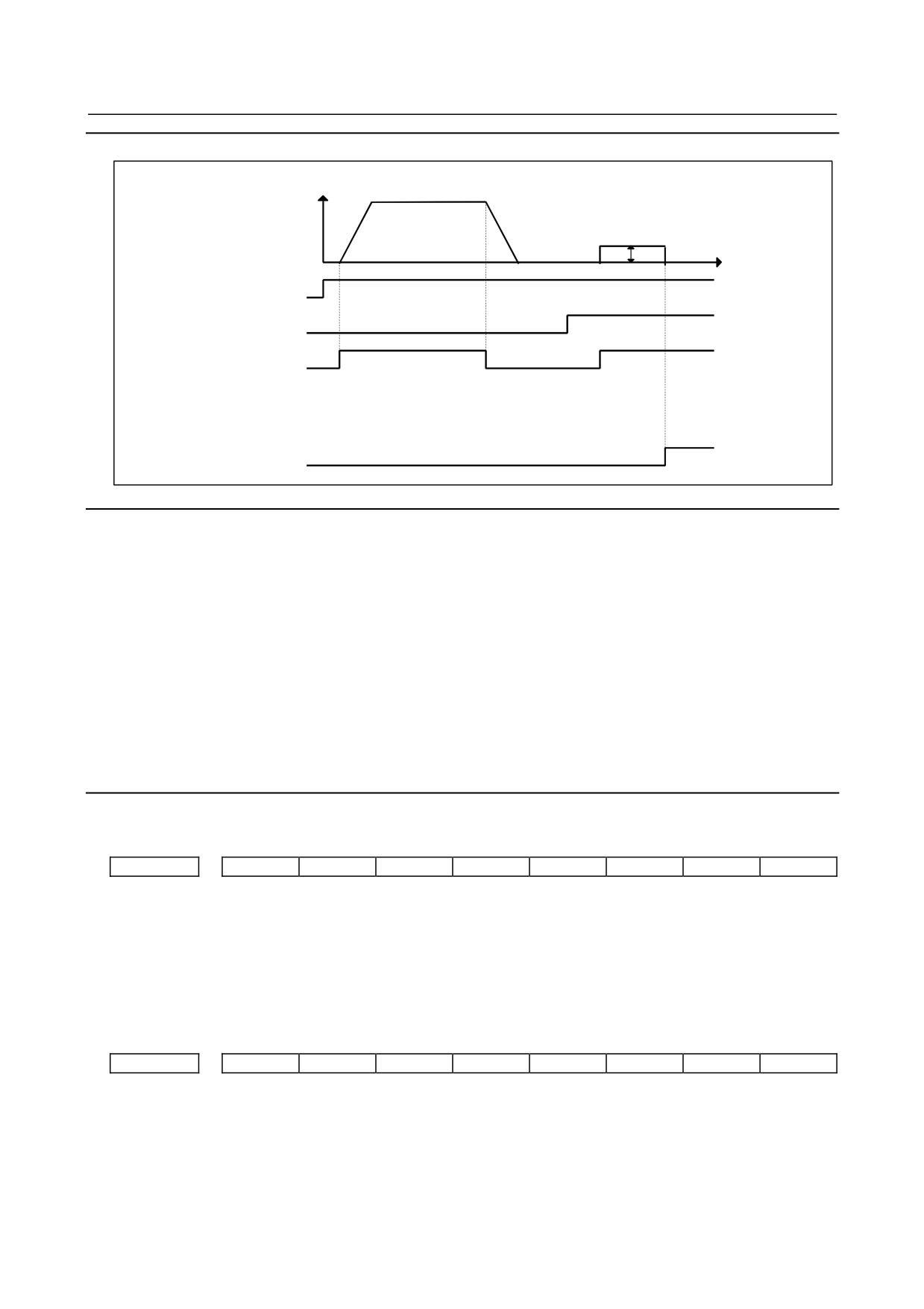
<1> Jog-feed the axis for which you want to set a reference position in the reference position return
direction and stop it a little short of the reference position.
<2> Select the manual reference position return mode and set the feed axis and direction select signal (+
or - direction) for the axis for setting the reference position to 1.
<3> The tool is positioned at the nearest grid (electric grid based on the one-rotation signal of the
position detector) in the reference position return direction specified in bit 5 (ZMIx) of parameter No.
1006 from the current position. This position is set as the reference position.
<4> After the in-position status is confirmed, the reference position return completion signal (ZPn) and
reference position establishment signal (ZRFn) are set to 1.
* Once a reference position is set up, simply providing the axis direction signal manually with the
ZRN signal set to “1” causes the axis to return to the reference position.
Parameter
There are the following related parameters.
#7
#6
#5
#4
#3
#2
#1
#0
1005
DLZx
[Input type] Parameter input
[Data type] Bit axis
#1 DLZx Function for setting the reference position without dogs
0: Disabled
1: Enabled
#7
#6
#5
#4
#3
#2
#1
#0
1006
ZMIx
[Input type] Parameter input
[Data type] Bit axis
- 331 -
8.DIGITAL SERVO
B-64305EN/03
NOTE
When this parameter is set, the power must be turned off before
operation is continued.
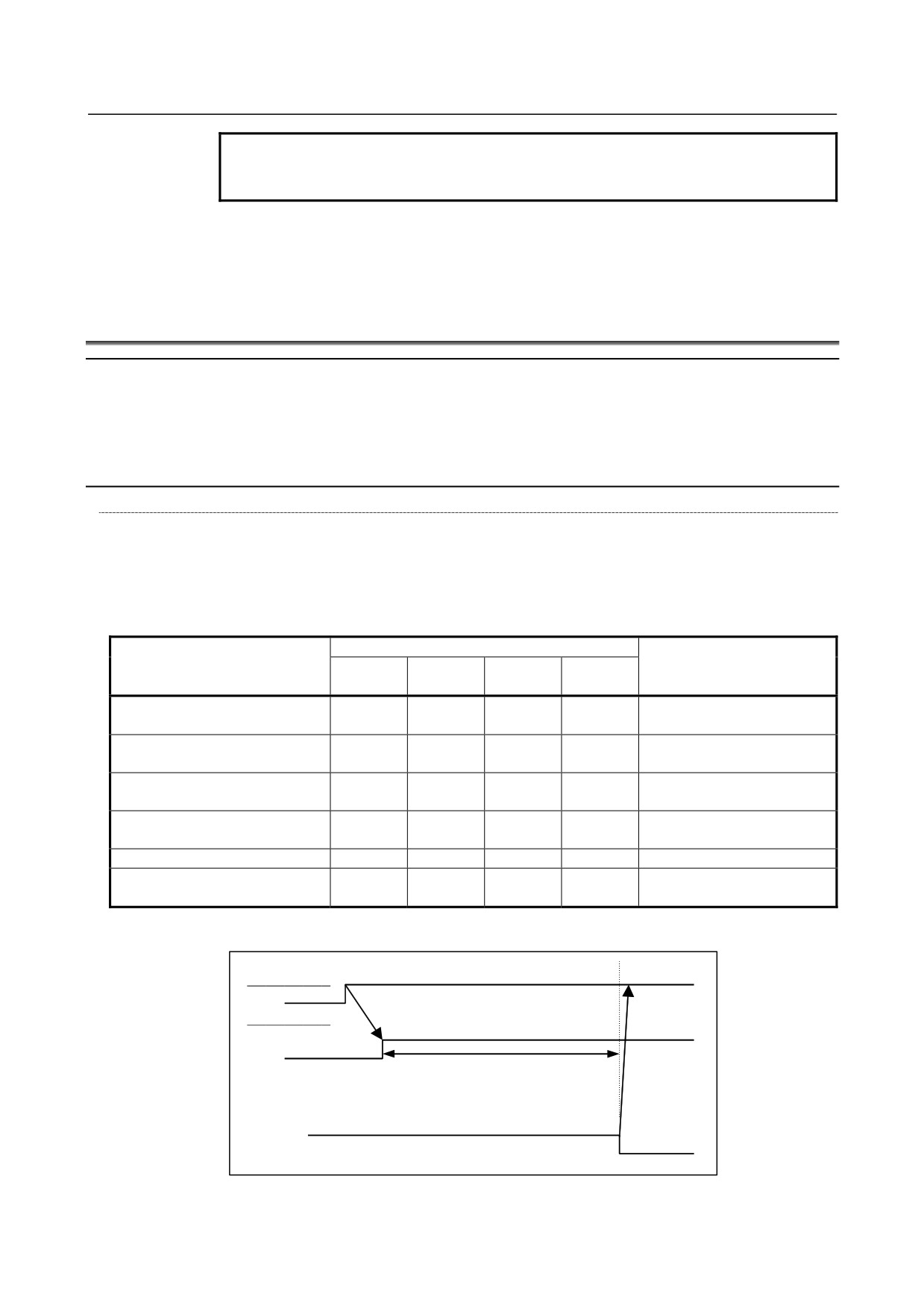
#5 ZMIx The direction of manual reference position return is:
0:
+ direction
1:
- direction
8.6
αi SERVO WARNING INTERFACE
Overview
The αi servo system can report the warning status before one of the following target alarms occurs.
When the warning status is entered, a report to the PMC is issued.
For example, this signal can be used by the machine for retracting tools from the time a warning occurs
by the time a servo alarm occurs.
Signal
Servo warning detail signals SVWRN1 to 4 <F093.4 to F093.7>
[Classification] Output signal
[Function] Reports the warning signal corresponding to the state of the servo amplifier.
[Output condition] The following table shows the warning statuses of the servo amplifier and their
corresponding warning signals.
Warning status signals
Time from when a warning
Corresponding alarm messages
SVWRN4
SVWRN3
SVWRN2
SVWRN1
state signal is issued to until
(F093.7)
(F093.6)
(F093.5)
(F093.4)
an alarm occurs
444 n AXIS: INV. COOLING FAN
Until overheat occurs
1
0
0
0
FAILURE
(inconstant)
601 n AXIS: INV. RADIATOR FAN
Until overheat occurs
1
0
0
1
FAILURE
(inconstant)
443 n AXIS: CNV. COOLING FAN
Until overheat occurs
1
1
0
0
FAILURE
(inconstant)
606 n AXIS: CNV. RADIATOR
Until overheat occurs
1
1
0
1
FAN FAILURE
(inconstant)
431 n AXIS: CNV. OVERLOAD
1
1
1
0
One minute
607 n AXIS: CNV. SINGLE
PSMR: Five seconds,
1
1
1
1
PHASE FAILURE
PSM: One minute
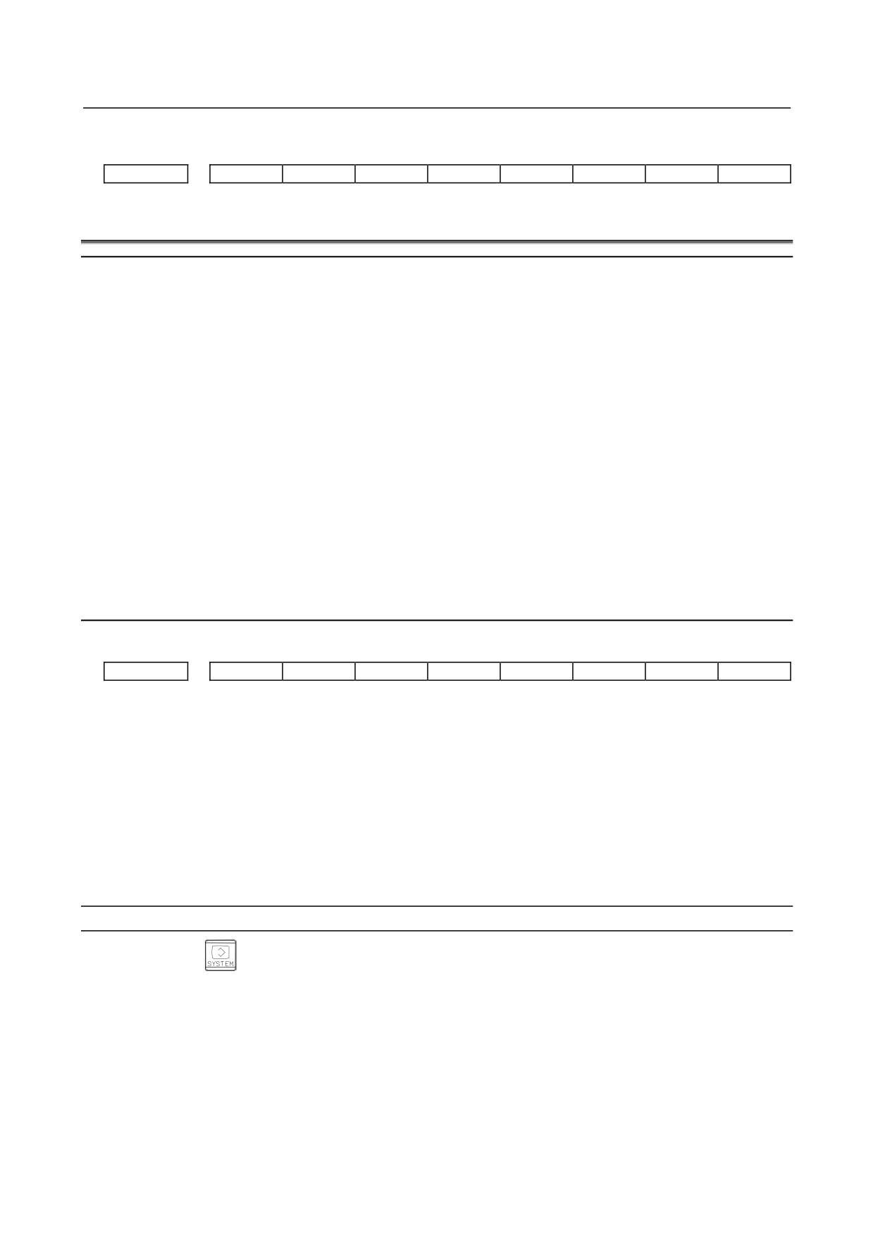
A timing chart for handling a warning is shown below.
Occurrence of a warning
Servo amplifier
SVWRN1-4
(Warning)
PMC
Perform deceleration stop or block stop
during this time period with the PMC to
stop the machine without damage. The
time period varies with the warning type.
Activation
Occurrence and stop of the alarm corresponding to a warning
- 332 -
B-64305EN/03
8.DIGITAL SERVO
Signal address
#7
#6
#5
#4
#3
#2
#1
#0
F093
SVWRN4
SVWRN3
SVWRN2
SVWRN1
8.7
αi SERVO INFORMATION SCREEN
Overview
In the αi servo system, ID information output from each of the connected units is obtained and output to
the CNC screen.
The units that have ID information are shown below.
(Remark: Some instances of these units do not have ID information.)
-
Servo motor
-
Pulsecoder
-
Servo amplifier module
-
Power supply module
ID information is automatically read from each of the connected units during first startup of the CNC and
then recorded. Next time (and the subsequent time) the CNC is started, the ID information that can be
read is compared with one recorded at the first startup time in order to monitor any change to the
connected units. (If there is a difference between them, the alarm mark (*) appears.)
The recorded ID information can be edited. Therefore, the ID information of an unit that does not have ID
information can be displayed. (However, the alarm mark (*) indicating a difference between these IDs
appears.)
Parameter
#7
#6
#5
#4
#3
#2
#1
#0
13112
SVI
IDW
[Input type] Parameter input
[Data type] Bit path
#0 IDW Editing on the servo or spindle information screen is:
0: Prohibited.
1: Not prohibited.
#1 SVI The servo information screen is:
0: Displayed.
1: Not displayed.
Displaying the servo information screen
1
Press the
function key, then press the [SYSTEM] soft key.
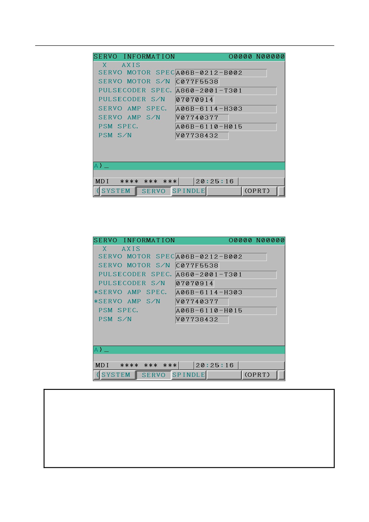
2
Press the [SERVO] soft key to display the screen as shown below.
- 333 -
8.DIGITAL SERVO
B-64305EN/03
* Servo information is stored in flash ROM. If there is a difference between the ID information in
screen and the actual ID information, the corresponding items are preceded by *, as shown
below.
Additional Information
Even if replacement is performed reasonably such as for repairing, this function
incorrectly indicates the * mark when it detects the replacement.
To clear the * mark, follow the steps below to update the registered data, as
described in the editing section later.
(1) Make the registered data editable. (Bit 0 (IDW) of parameter No. 13112 = 1)
(2) On the edit screen, place the cursor on the item from which you want to
delete the * mark.
(3) Operate the soft keys [READ ID], [INPUT], and [SAVE] in that order.
- 334 -
B-64305EN/03
8.DIGITAL SERVO
Editing the servo information screen
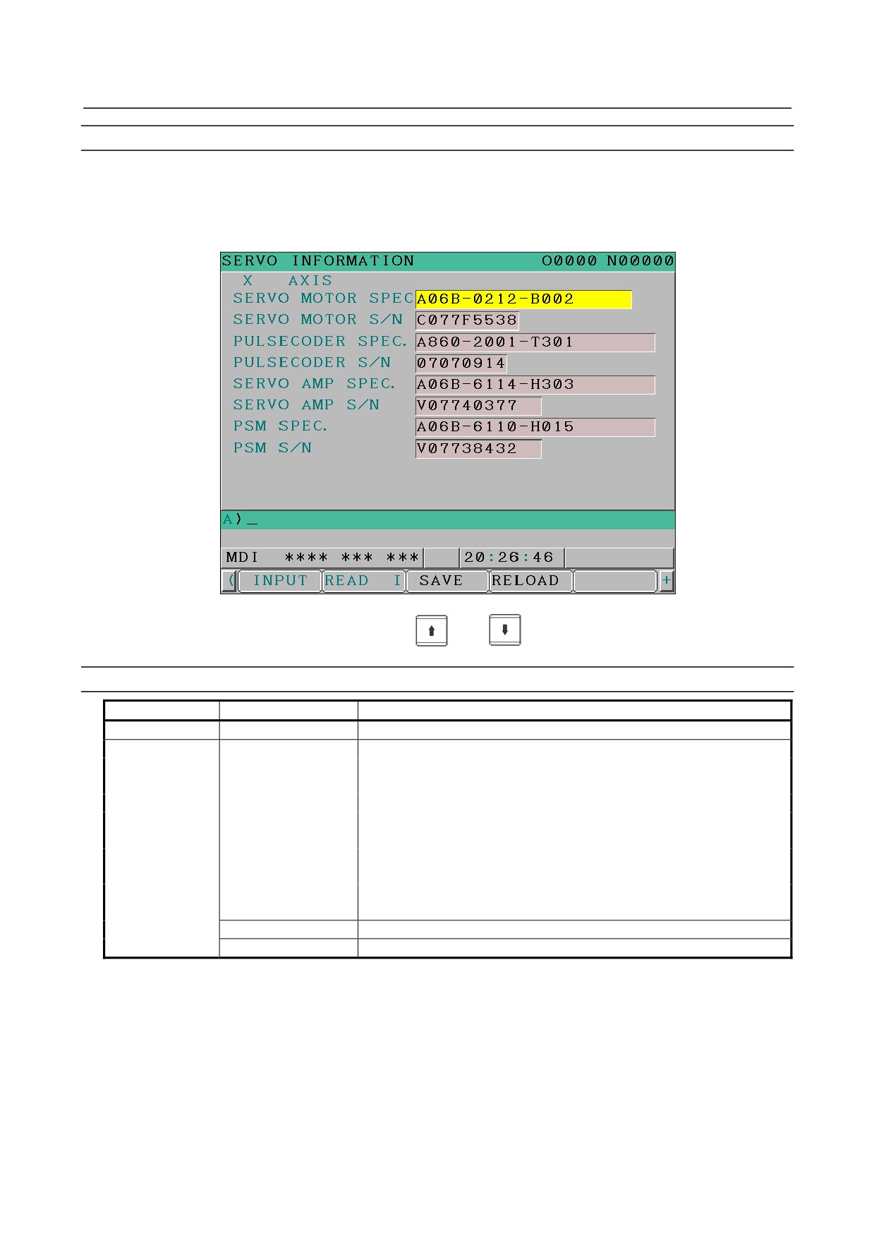
1
Assume that bit 0 (IDW) of parameter No. 13112 = 1.
2
Press the MDI switch on the machine operator's panel.
3
Follow the steps shown in "Displaying the servo information screen" to display the screen as shown
below.
4
To move the cursor on the screen, use the
and
keys.
Screen operation
Mode
Key operation
Use
Viewing (*1)
Page key
Scrolls up or down on a screen-by-screen basis.
Editing (*2)
Soft key
[INPUT]
Replace the selected ID information at the cursor position with the
character string in key-in buffer.
[CANCEL]
Deletes the character string in key-in buffer.
[READ ID]
Transfers the ID information the connected device at the cursor has to
the key-in buffer. Only the items preceded by * (*3) are valid.
[SAVE]
Saves the ID information that has been changed on the servo information
screen in flash ROM.
[RELOAD]
Cancels the ID information that has been changed on the servo
information screen and loads ID information from flash ROM.
Page key
Scrolls up or down on a screen-by-screen basis.
Cursor key
Scrolls up or down the selection of ID information.
*1 Viewing mode: when bit 0 (IDW) of parameter No. 13112 = 0
*2 Editing mode: when bit 0 (IDW) of parameter No. 13112 = 1
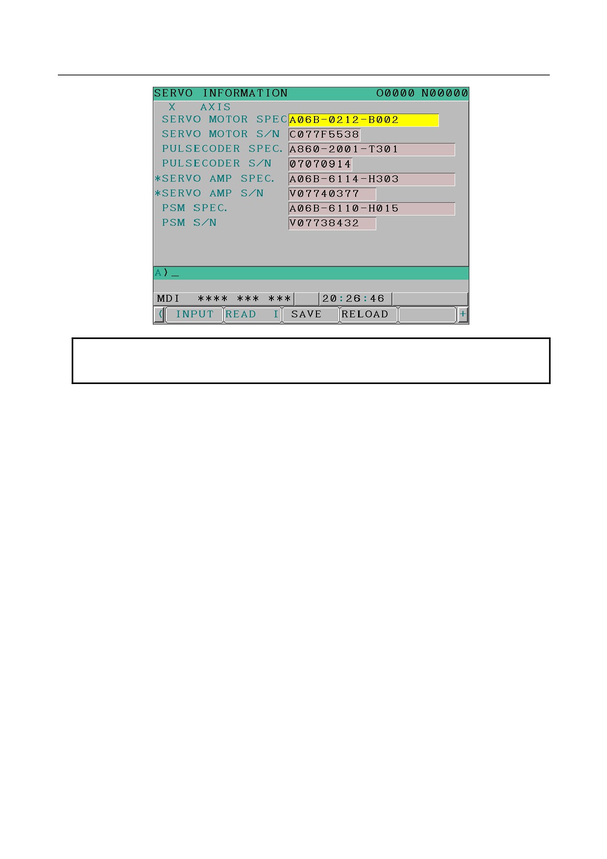
*3 If there is a difference between the ID information in screen and the actual ID information, the
corresponding items are preceded by *.
- 335 -
8.DIGITAL SERVO
B-64305EN/03
NOTE
For axes that are not used by the αi servo system, ID information of connected
units cannot be obtained.
- 336 -
B-64305EN/03
9.AC SPINDLE
9 AC SPINDLE
This chapter outlines the serial interface spindle amplifiers and explains related parameters.
9.1 SERIAL INTERFACE AC SPINDLE
338
9.1.1 OUTLINE OF SPINDLE CONTROL
338
9.1.2 SPINDLE SETTING AND TUNING SCREEN
340
9.1.3 AUTOMATIC SETTING OF STANDARD PARAMETERS
347
9.1.4 WARNING INTERFACE
349
9.1.5 SPINDLE INFORMATION SCREEN
350
- 337 -
9.AC SPINDLE
B-64305EN/03
9.1
SERIAL INTERFACE AC SPINDLE
9.1.1
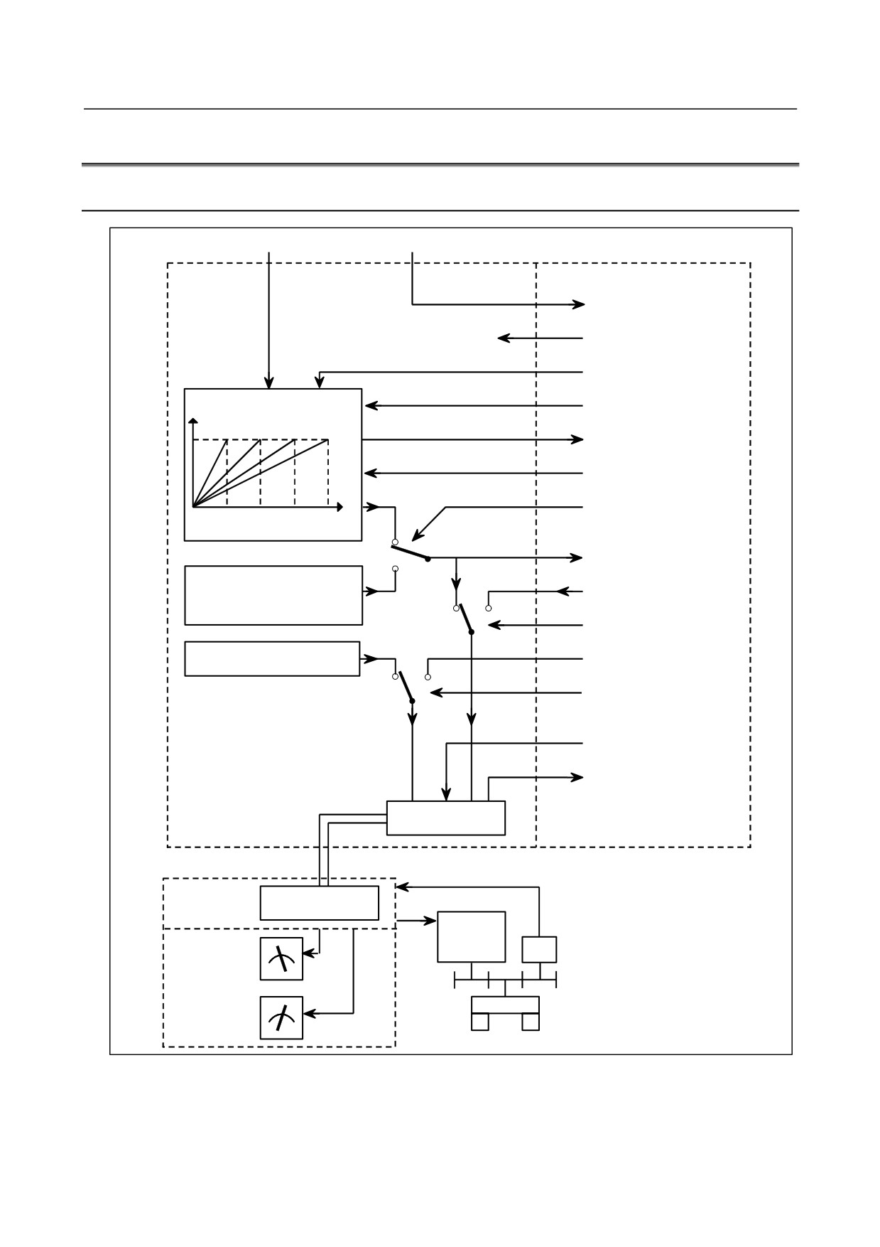
Outline of Spindle Control
S command
M command
NC
PMC
M03, M04, M05, M19
FIN
*SSTP (Spindle stop)
Motor speed
SOVx (Spindle override)
SF, GR1O, GR2O, GR3O
(For M series)
GR1, GR2 (For T series)
S
SOR (Orientation)
(Parameters Nos. 3735 to
3752)
0
R01O to R12O
1
Orientation speed
(bit 1 (ESF) of parameter No.3705,
R01I to R12I
parameter No.3732, and bit 5
0
1
(ORM) of parameter No.3706)
SIND
Output polarity (Bits 7 (CWM) and
SGN (0=+, 1=-)
6 (TCW) of parameter No.3706)
0
1
SSIN
*ESP, MRDY,
SFR, SRV, ORCM etc.
SST, SDT, SAR, LDT1, LDT2
ORAR, ALM etc.
Communication
function
Communication cable
Serial
spindle
Communication
amplifier
function
Spindle
Operator's panel
motor
PC
Load meter
LM
Speedometer
Spindle
SM
- 338 -
B-64305EN/03
9.AC SPINDLE
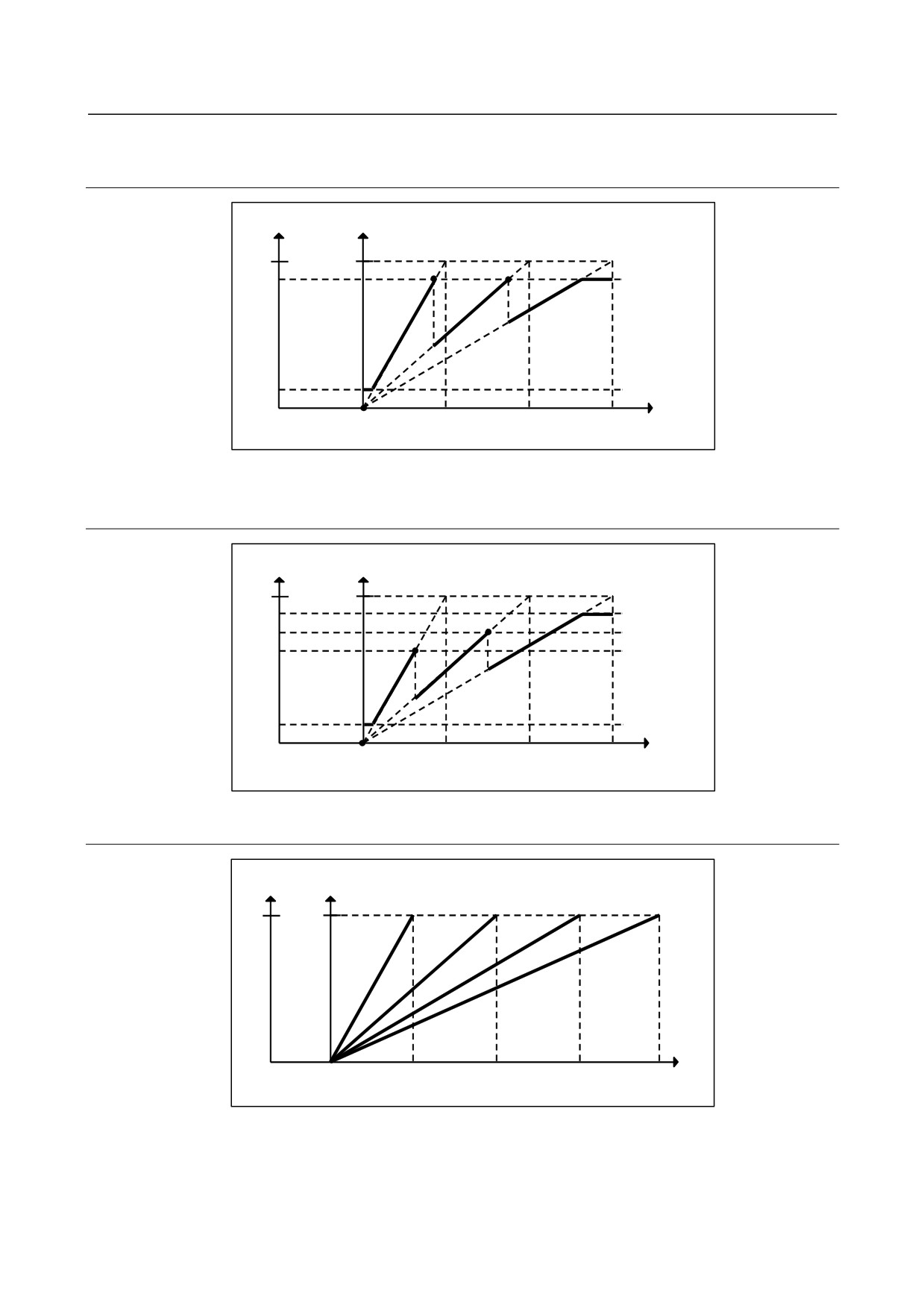
9.1.1.1 Method A of gear change for M series
(Bit 2 (SGB) of Parameter No.3705 = 0)
Output
Motor speed
4095
Max
Parameter
Gear 2
Gear 3
No.3736
Gear 1
Parameter
No.3735
0
S code
0
Parameter
Parameter
Parameter
(min-1)
No.3741
No.3742
No.3743
9.1.1.2 Method B of gear change for M series
(Bit 2 (SGB) of Parameter No.3705 = 1)
Output
Motor speed
Parameter
4095
Max
No.3736
Parameter
No.3752
Parameter
Gear 1
Gear 2
Gear 3
No.3751
Parameter
No.3735
0
S code
0
Parameter
Parameter Parameter
(min-1)
No.3741
No.3742
No.3743
9.1.1.3 T series
Output Motor speed
4095
Max
Gear 1
Gear 2
Gear 3
Gear 4
S code
(min-1)
0
0
0
Parameter
Parameter Parameter Parameter
No.3741
No.3742
No.3743
No.3744
- 339 -
9.AC SPINDLE
B-64305EN/03
9.1.2
Spindle Setting and Tuning Screen
9.1.2.1 Display method
(1) Confirm the parameters
#7
#6
#5
#4
#3
#2
#1
#0
3111
SPS
[Input type] Setting input
[Data type] Bit path
#1 SPS The spindle setting screen is:
0: Not displayed.
1: Displayed.
(2) Press the function key
to select the screen for setting parameters and other data.
(3) Press the continuous menu key
(4) Press the soft key [SP.SET]. Then, the spindle setting and tuning screen appears.
(5) The following screens are provided. These screens can be selected using soft keys.
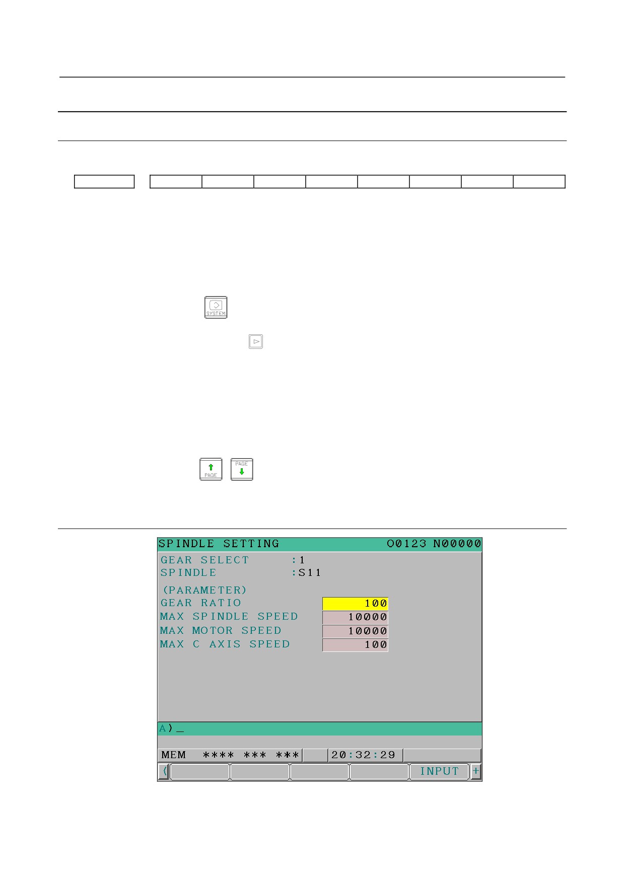
<1> [SP.SET] : Spindle setting screen
<2> [SP.TUN] : Spindle tuning screen
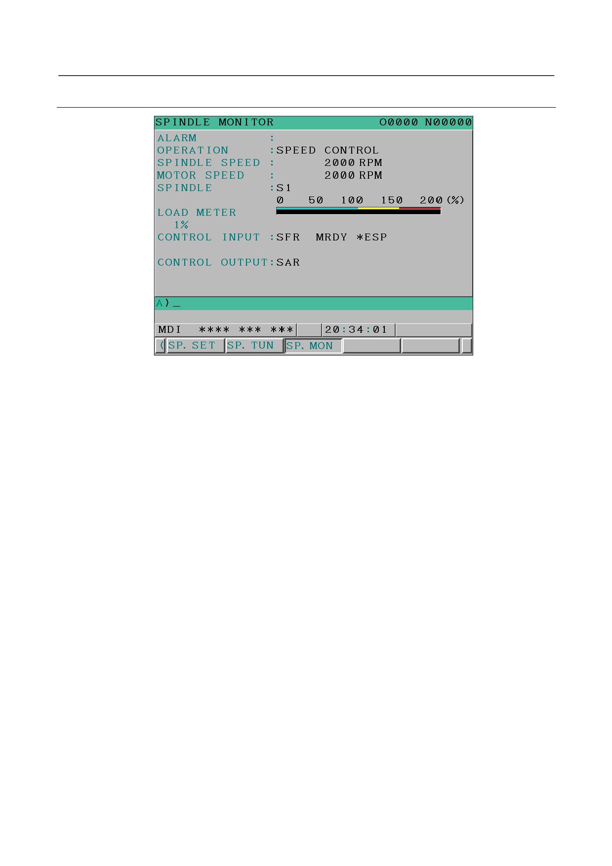
<3> [SP.MON] : Spindle monitor screen
(6) With the page keys
, a spindle to be displayed can be selected (only when multiple
serial spindles are connected).
9.1.2.2 Spindle setting screen
-
Gear selection
The gear select status on the machine side is displayed.
- 340 -
B-64305EN/03
9.AC SPINDLE
Clutch/gear signal
Indication
CTH1n
CTH2n
1
0
0
2
0
1
3
1
0
4
1
1
-
Spindle
Select a spindle for which data is to be set.
S11 :
1st spindle
S21 :
2nd spindle
S31 :
3rd spindle
-
Parameters
S11:
S21:
S31:
1st spindle
2nd spindle
3rd spindle
Gear ratio (HIGH)
4056
4056
4056
Gear ratio (MEDIUM HIGH)
4057
4057
4057
Gear ratio (MEDIUM LOW)
4058
4058
4058
Gear ratio (LOW)
4059
4059
4059
Max. spindle speed (gear1)
3741
3741
3741
Max. spindle speed (gear2)
3742
3742
3742
Max. spindle speed (gear3)
3743
3743
3743
Max. spindle speed (gear4)
3744
3744
3744
Max. motor speed
4020
4020
4020
Max. Cs axis speed
4021
4021
4021
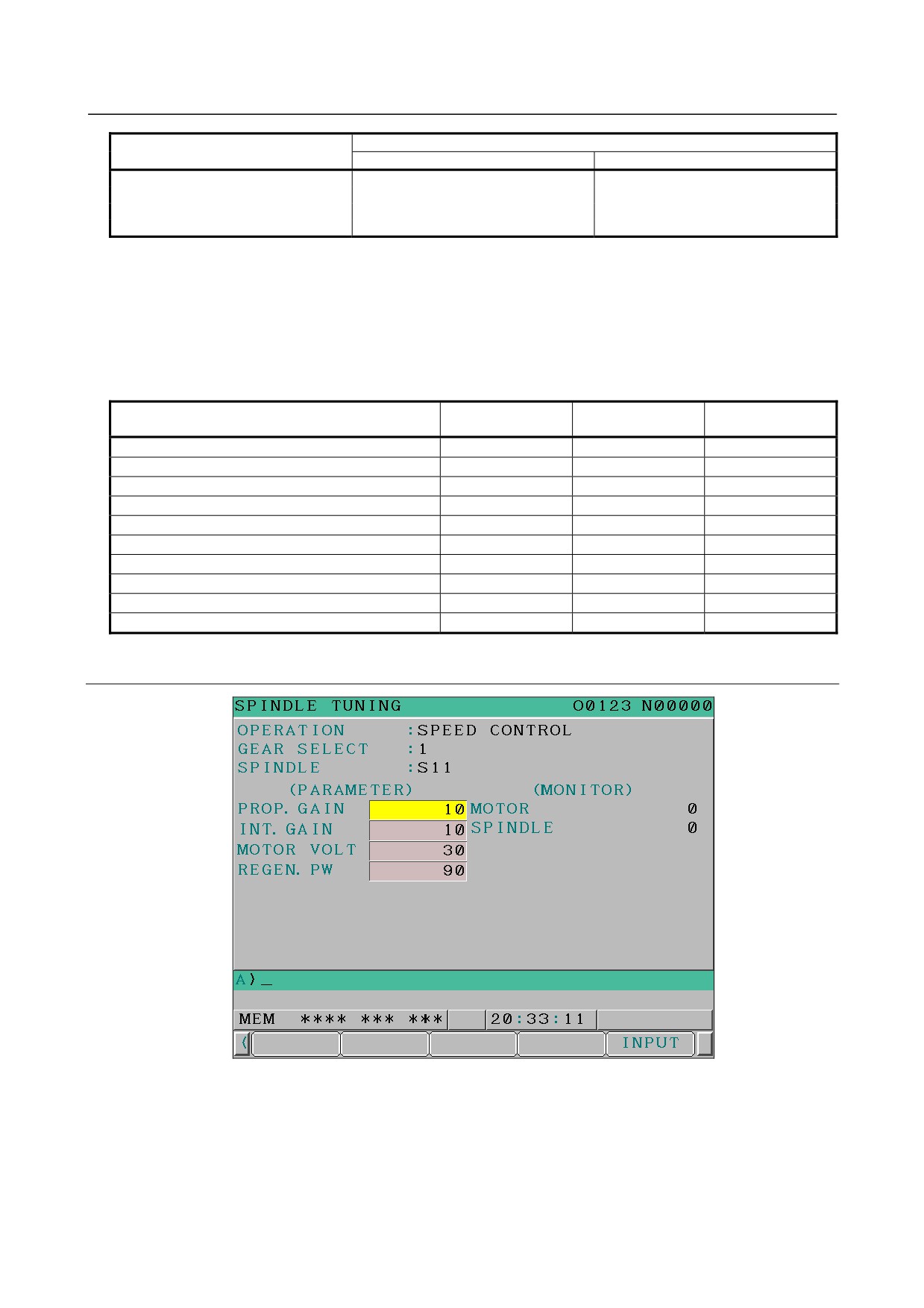
9.1.2.3 Spindle tuning screen
-
Operation mode
1
: SPEED CONTROL
2
: SPINDLE ORIENTATION
3
: SYNCHRONIZATION CONTROL
4
: RIGID TAPPING
5
: SP.CONTOURING CONTROL
6
: SP.POSITIONING CONTROL (T series)
- 341 -
9.AC SPINDLE
B-64305EN/03
-
Gear selection
-
Spindle
The descriptions of these two items are the same as those for the spindle setting screen.
-
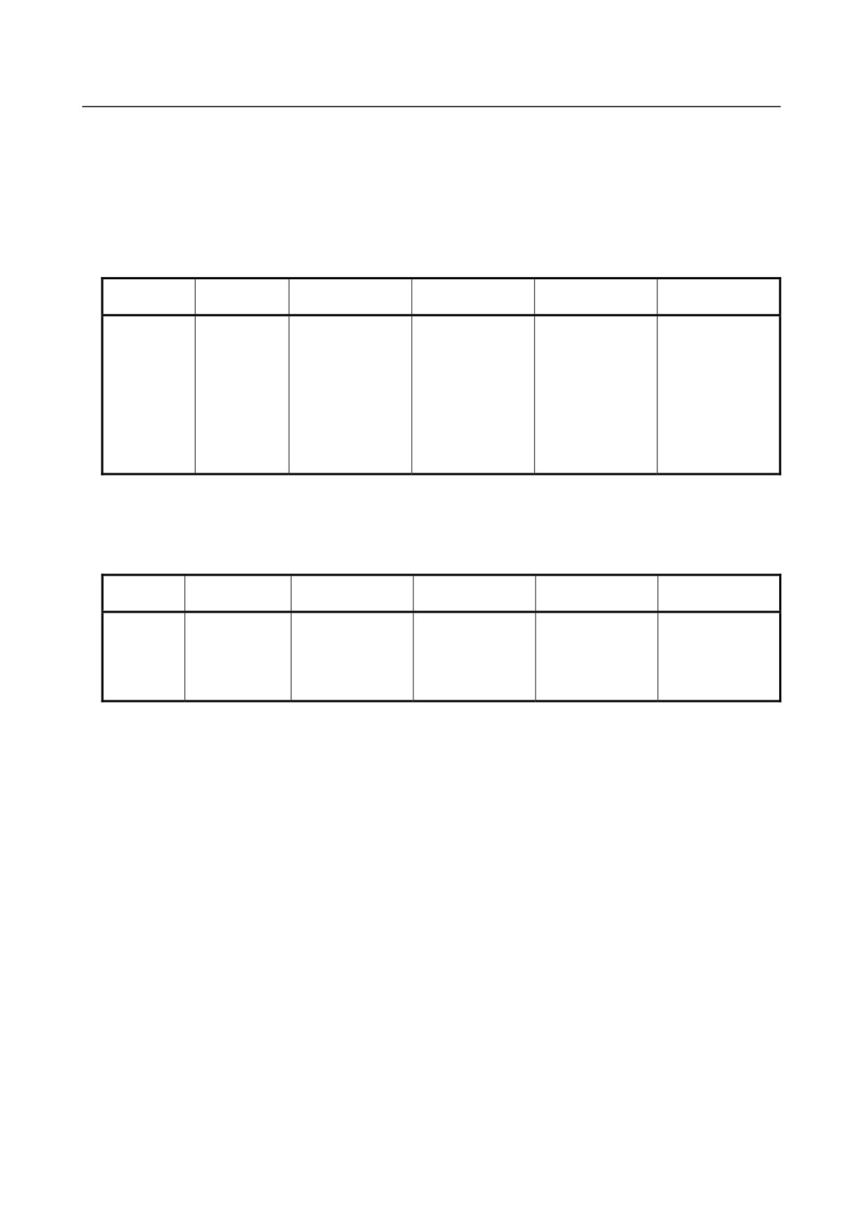
Displayed parameters
The displayed parameters vary depending on the operation mode.
Normal
Synchronous
Spindle positioning
Orientation
Rigid tapping
Cs contour control
operation
control
control (T series)
Proportional gain
Proportional gain
Proportional gain
Proportional gain
Proportional gain
Proportional gain
Integral gain
Integral gain
Integral gain
Integral gain
Integral gain
Integral gain
Motor voltage
Loop gain
Loop gain
Loop gain
Loop gain
Loop gain
Regenerative
Motor voltage
Motor voltage
Motor voltage
Motor voltage
Motor voltage
power
ORAR gain (%)
Acceleration/
ZRN gain (%)
ZRN gain (%)
ZRN gain (%)
Shift spindle stop
deceleration constant
Shift reference position
Shift reference position
Shift reference position
position
Shift reference position
Shift reference
position
*1) For the parameter numbers corresponding to the displayed parameter items, see Section 9.1.2.5.
-
Displayed monitoring items
The displayed monitoring items vary depending on the operation mode.
Normal
Synchronous
Spindle positioning
Orientation
Rigid tapping
Cs contour control
operation
control
control (T series)
Motor speed
Motor speed
Motor speed
Motor speed
Motor speed
Motor speed
Spindle speed
Spindle speed
Spindle speed
Spindle speed
Spindle speed
Feedrate
Position deviation S
Position deviation S1
Position deviation S
Position deviation S
Position deviation S
Position deviation S2
Position deviation Z
Synchronous deviation
Synchronous deviation
*1)
|Spindle data|
Motor speed [min-1] =
× Max. motor speed (*)
16383
(*) Parameter No. 4020
- 342 -
B-64305EN/03
9.AC SPINDLE
9.1.2.4 Spindle monitor screen
- 343 -