FANUC SERVO AMPLIFIER a series. DESCRIPTIONS (B-65162E/03) - page 22
B-65162E/03
APPENDIX
F. SPECIFICATIONS OF CABLES
Sym-
FANUC specification
Use
Specification
bol
(complete cable)
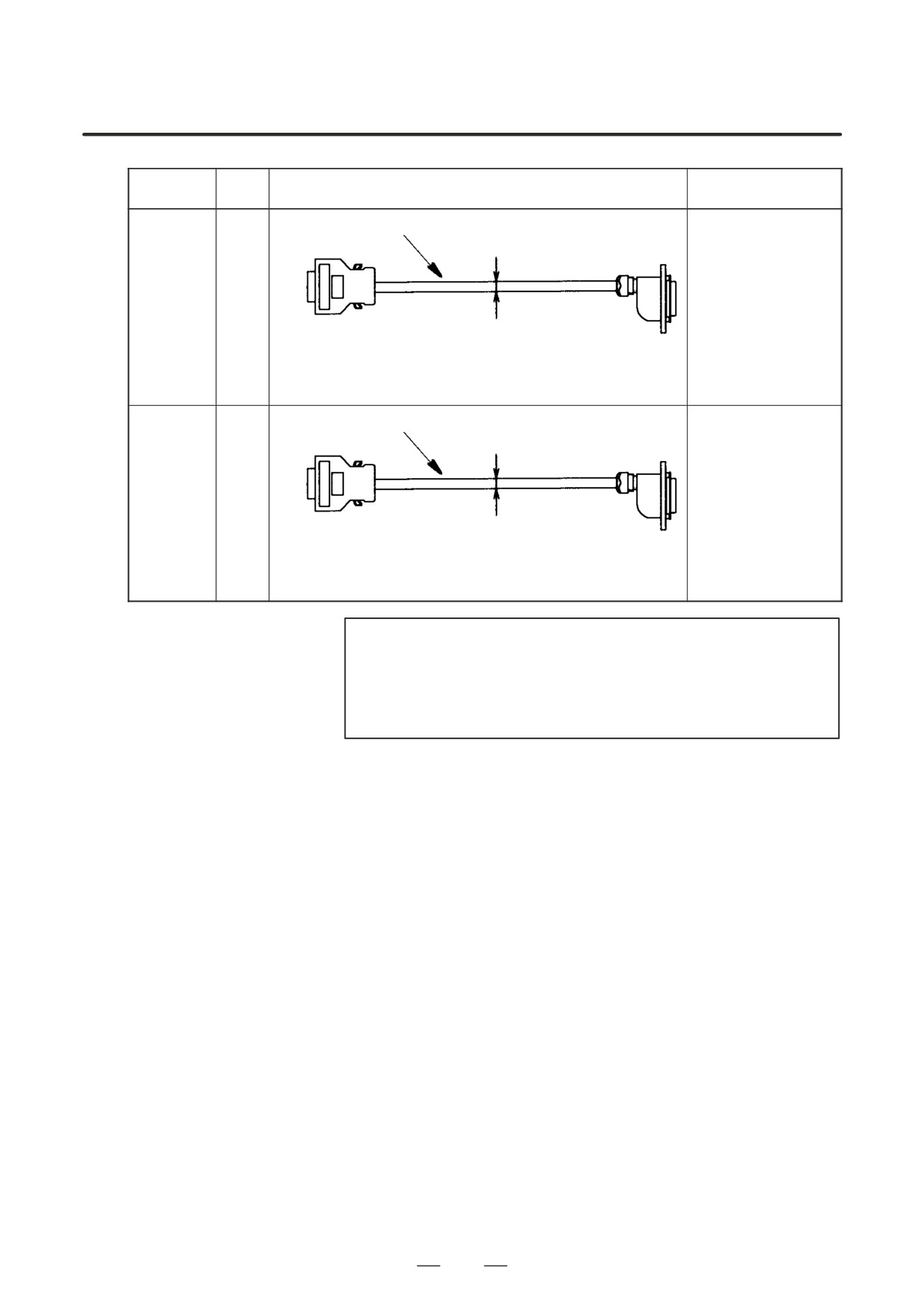
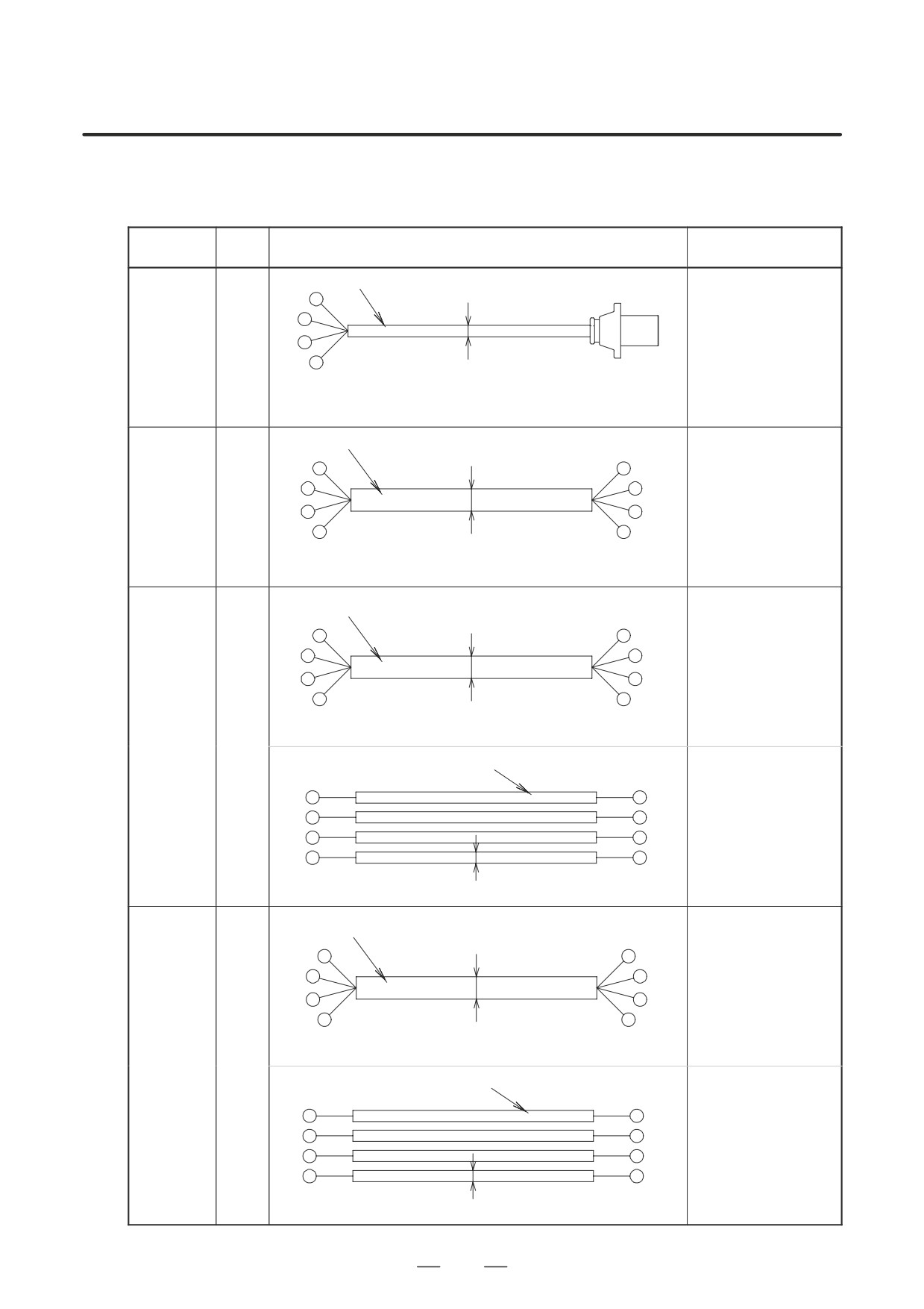
Composite 12-conductor group shielded cable,
6 conductors 0.5mm2 (20/0.18)
3 pairs 0.18 mm2 (7/0.18) (Note 4)
α1, α2,
αM2, αM2.5
(for FS15B,
A06B-6050-K853
K22
16, 18, 20,
(Cable length : 14m)
SVM pulse
φ8.5
SPM side (JY2)
coders)
Motor side
Connector manufactured by Hirose Electric
Connector: FI40A-20S
Connector kit:
Housing: FI-20-CV5
A06B-6050-K1
15
Composite 12-conductor group shielded cable,
6 conductors 0.5mm2 (20/0.18)
3 pairs 0.18 mm2 (7/0.18) (Note 4)
α1, α2,
αM2, αM2.5
(for FS0,
A06B-6050-K854
K22
FS15A,
(Cable length : 14m)
pulse cod-
φ8.5
CNC side (M**)
ers)
Motor side
Connector manufactured by Honda Tsushin
Kogyo
Connector kit:
Connector: MR-20LMH
A06B-6050-K1
15
NOTE
4
FANUC drawing number (wire only): A66L-0001-0286
Contact:
Hitachi Cable Trading Company
03(3255)5415
Oki Electric Cable Co., Ltd.
044(766)3171
633
F. SPECIFICATIONS OF CABLES
APPENDIX
B-65162E/03
Sym-
FANUC specification
Use
Specification
bol
(complete cable)
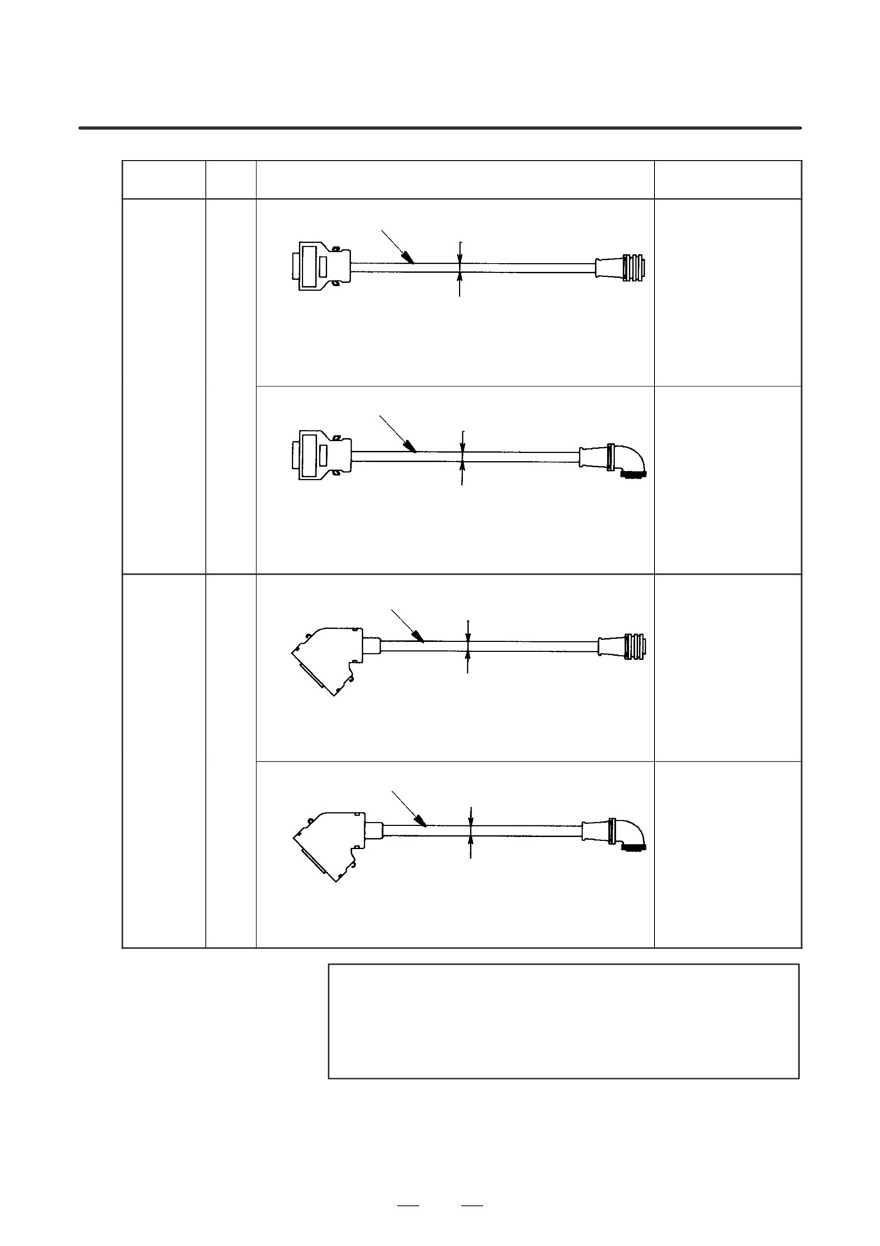
Composite 12-conductor group shielded cable,
6 conductors 0.5mm2 (20/0.18)
3 pairs 0.18 mm2 (7/0.18) (Note 4)
α3, α6, α12,
A02B-0200-K800
α22, α30,
Motor side
(Cable length : 14m)
NC side(JF*)
α40, α65,
φ8.5
Connector:
SVM side (JF*)
α100, α150,
H/MS3106A20-29SW(11)
Connector manufactured by
αM3, αM6,
JA06A-20-29SW-JI-EB
Hirose Electric
Cable clamp:
αM9, αM22,
Connector: FI40-2015S
H/MS3057-12A
αM30, αC3,
Housing: FI-20-CV
αC6, αC12,
K22
Composite 12-conductor group shielded cable,
αC22, αL3,
6 conductors 0.5mm2 (20/0.18)
αL6, αL9,
3 pairs 0.18 mm2 (7/0.18) (Note 4)
αL25, αL50
(for FS15B,
16, 18, 20,
A02B-0200-K801
SVM pulse
Motor side
(Cable length : 14m)
coders)
NC side(JF*)
φ8.5
Connector:
SVM side (JF*)
H/MS3106A20-29SW(11)
Connector manufactured by
JA06A-20-29SW-JI-EB
Hirose Electric
Cable clamp:
Connector: FI40-2015S
H/MS3057-12A
Housing: FI-20-CV
Composite 12-conductor group shielded cable,
6 conductors 0.5mm2 (20/0.18)
3 pairs 0.18 mm2 (7/0.18) (Note 4)
α3, α6, α12,
A02B-0098-K860
α22, α30,
Motor side
(Cable length : 14m)
α40, α65,
φ8.5
Connector:
α100, α150,
H/MS3106A20-29SW(11)
NC side(JF*)
αM3, αM6,
JA06A-20-29SW-JI-EB
Connector manufactured by
αM9, αM22,
Honda Tsushin Kogyo
Cable clamp:
H/MS3057-12A
αM30, αC3,
Connector: MR-20LMH
αC6, αC12,
K22
αC22, αL3,
Composite 12-conductor group shielded cable,
6 conductors 0.5mm2 (20/0.18)
αL6, αL9,
3 pairs 0.18 mm2 (7/0.18) (Note 4)
αL25, αL50
(for FS0
and FS15A
A02B-0098-K861
pulse cod-
Motor side
(Cable length : 14m)
ers)
φ8.5
Connector:
H/MS3106A20-29SW(11)
NC side(M*)
JA06A-20-29SW-JI-EB
Connector manufactured by
Cable clamp:
Honda Tsushin Kogyo
H/MS3057-12A
Connector: MR-20LMH
NOTE
4
FANUC drawing number (wire only): A66L-0001-0286
Contact:
Hitachi Cable Trading Company
03(3255)5415
Oki Electric Cable Co., Ltd.
044(766)3171
634
B-65162E/03
APPENDIX
F. SPECIFICATIONS OF CABLES
Sym-
FANUC specification
Use
Specification
bol
(complete cable)
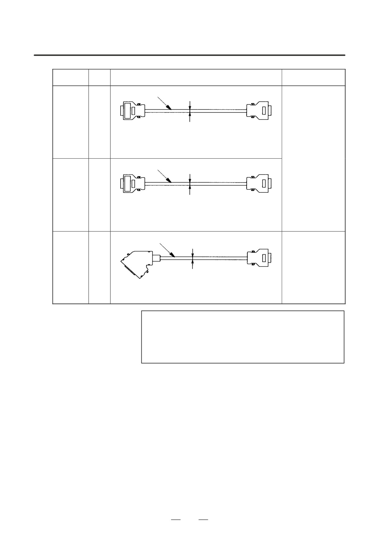
Twisted pair unified shield 10-pair 0.09mm2 (7/0.127) (Note 5)
CNC-AMP-
K23
TYPE A I/F
CNC side (JV**)
φ6.2
SVM side (JV**)
Connector manufactured by
Connectormanufactured
Honda Tsushin Kogyo
by Honda Tsushin Kogyo
Connector: PCR-E20FA
Connector: PCR-E20FA
Housing: PCR-V20LA
Housing: PCR-V20LA
A02B-0120-K800
(Cable length : 5m)
Twisted pair unified shield 10-pair 0.09mm2 (7/0.127) (Note 5)
CNC-AMP-
K23
TYPE B I/F
CNC side (JV**)
φ6.2
SVM side (JV**)
Connector manufactured by
Connectormanufactured
Honda Tsushin Kogyo
by Honda Tsushin Kogyo
Connector: PCR-E20FA
Connector: PCR-E20FA
Housing: PCR-V20LA
Housing: PCR-V20LA
Twisted pair unified shield 10-pair 0.09mm2 (7/0.127) (Note 5)
CNC-AMP
A02B-0098-K841
K23
FS0, FS15A
(Cable length : 5m)
φ6.2
SVM side (JV**)
CNC side (M**)
Connectormanufactured
Connector manufactured by
by Honda Tsushin Kogyo
Honda Tsushin Kogyo
Connector: PCR-E20FA
Connector: MR-20LMH
Housing: PCR-V20LA
NOTE
5
FANUC drawing number (wire only): A66L-0001-0286#10P
Contact:
Hitachi Cable Trading Company
03(3255)5415
Oki Electric Cable Co., Ltd.
044(766)3171
635
F. SPECIFICATIONS OF CABLES
APPENDIX
B-65162E/03
Sym-
FANUC specification
Use
Specification
bol
(complete cable)
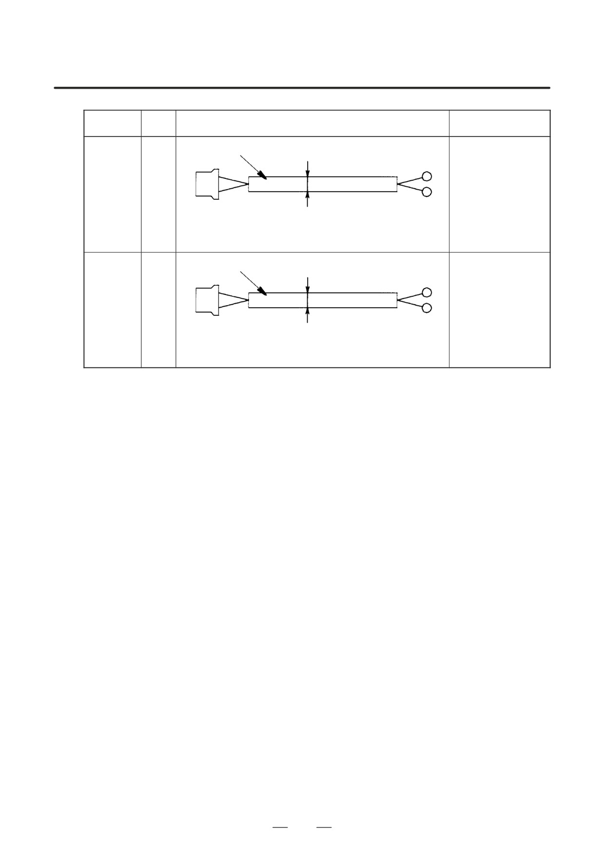
Vinyle cabtyre cable JIS C 3312 2-core 1.25mm2 (50/0.18)
SVM-DBM
(for interlock
K24
signal)
SVM side (CX8)
φ9.6
Dynamic brake side
Connector manufactured by AMP Japan
T2-4
Receptacle housing: 2-178128-3
Receptacle contact: 1-175218-2
Vinyle cabtyre cable JIS C 3312 2-core 1.25mm2 (50/0.18)
SVM-DBM
(for driving
K25
coil)
SVM side (CX9)
φ9.6
Dynamic brake side
Connector manufactured by AMP Japan
T2-4
Receptacle housing: 2-178128-3
Receptacle contact: 1-175218-2
636
B-65162E/03
APPENDIX
F. SPECIFICATIONS OF CABLES
(3) Spindle amplifier module
Sym-
FANUC specification
Use
Specification
bol
(complete cable)
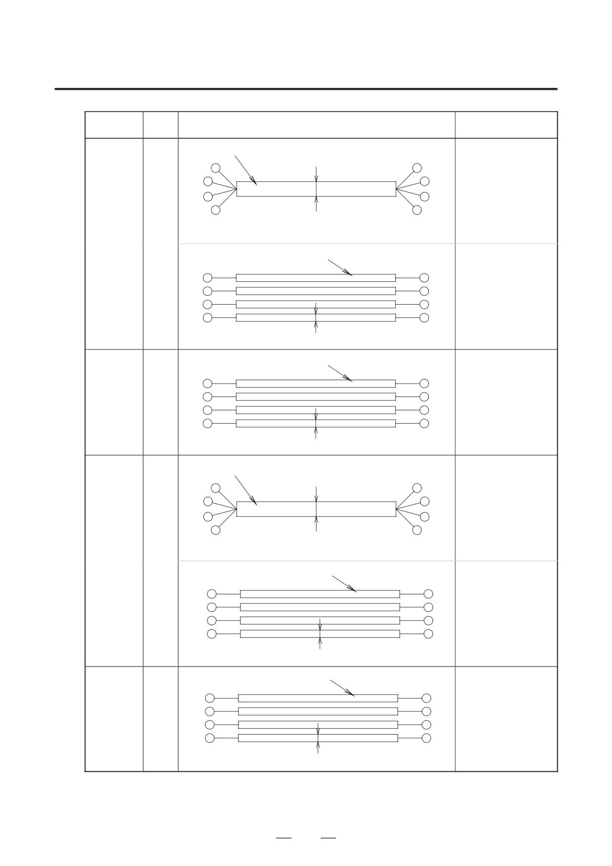
Vinyle cabtyre cable JIS C 3312 4-core 0.75mm2 (30/0.18)
A06B-6050-K801
α0.5
(Cable length : 14m)
(Motor
K10
power line)
A06B-6050-K803
φ10
Motor side
(Cable length : 7m)
SPM side (TB2)
AMP connector
T1.25-4
Connector kit :
A06B-6050-K121
Vinyle cabtyre cable JIS C 3312 4-core 2mm2 (37/0.26)
α1
(Motor
K10
power line)
φ12
SPM side (TB2)
Motor side
T2-4
T2-5
Vinyle cabtyre cable JIS C 3312 4-core 3.5mm2 (45/0.32)
φ14
SPM side (TB2)
Motor side
α1.5, α2
T5.5-4S
T5.5-5
(Motor
K10
power line)
Heat resistive vinyle cable 3.5mm2 (45/0.32)
SPM side (TB2)
Motor side
φ4.6
T5.5-4S
T5.5-5
Vinyle cabtyre cable JIS C 3312 4-core 5.5mm2 (70/0.32)
SPM side (TB2)
φ16.5
Motor side
α3
T5.5-4S
T5.5-5
(Motor
K10
power line)
Heat resistive vinyle cable 3.5mm2 (45/0.32)
SPM side (TB2)
Motor side
T5.5-4S
φ4.6
T5.5-5
637
F. SPECIFICATIONS OF CABLES
APPENDIX
B-65162E/03
Sym-
FANUC specification
Use
Specification
bol
(complete cable)
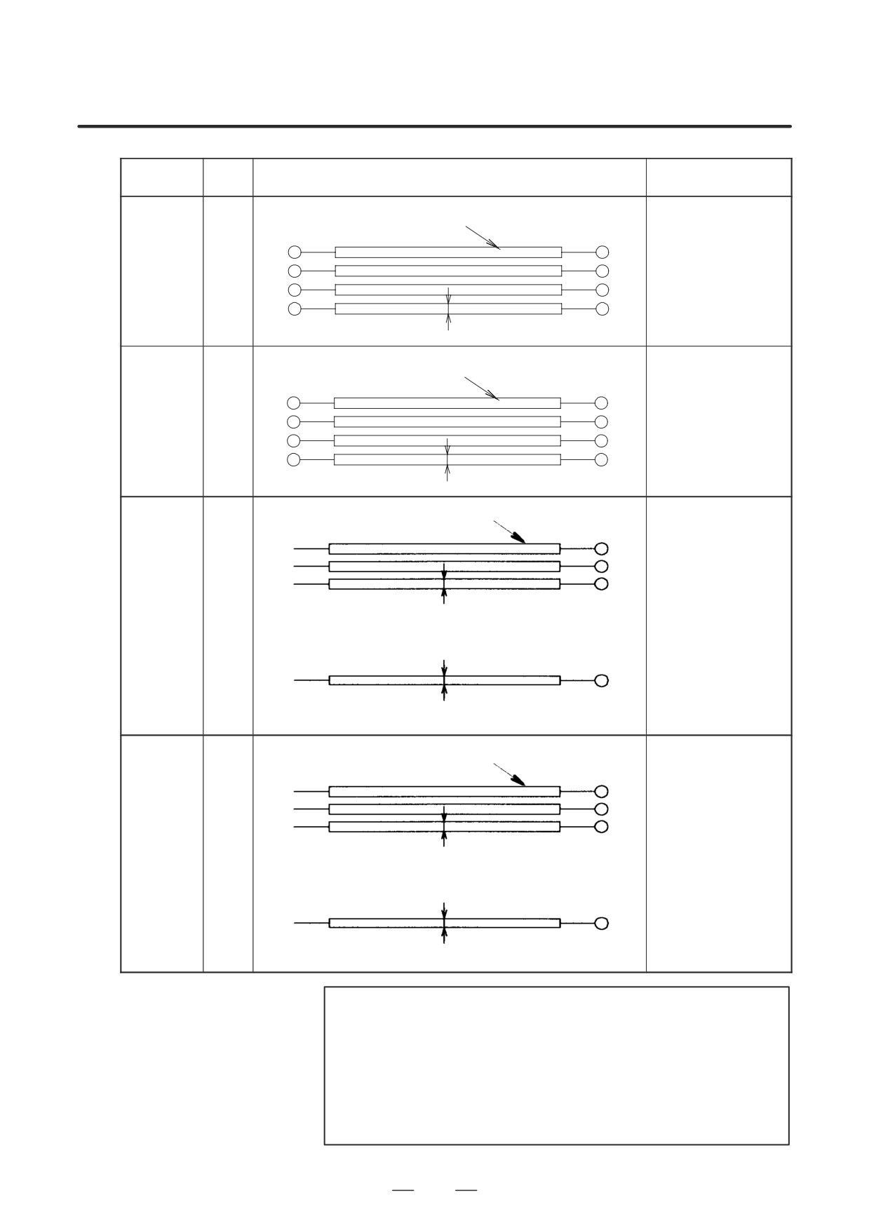
Vinyle cabtyre cable JIS C 3312 4-core 8mm2 (50/0.45)
φ20
α6
SPM side (TB2)
Motor side
αP8, αP12
T8-4S
T8-5
K10
(Motor
Heat resistive vinyle cable 3.5mm2 (45/0.32)
power line)
SPM side (TB2)
Motor side
T5.5-4S
φ4.6
T5.5-5
Heat resistive vinyle cable 5.5mm2 (35/0.45)
α8
αP15
K10
(Motor
power line)
SPM side (TB2)
Motor side
φ5.2
T5.5-4S
T5.5-5
Vinyle cabtyre cable JIS C 3312 4-core 14mm2 (88/0.45)
α12
SPM side (TB2)
φ24
Motor side
T14-6
T14-5
αP18
K10
(Motor
Heat resistive vinyle cable 8mm2 (50/0.45)
power line)
SPM side (TB2)
Motor side
φ5.8
T8-6
T8-5
Heat resistive vinyle cable 14mm2 (88/0.45)
α15
αP22
K10
(Motor
power line)
SPM side (TB2)
Motor side
φ7
T14-6
T14-5
638
B-65162E/03
APPENDIX
F. SPECIFICATIONS OF CABLES
Sym-
FANUC specification
Use
Specification
bol
(complete cable)
Heat resistive vinyle cable 14mm2 (88/0.45)
α18
αP30
K10
(Motor
power line)
SPM side (TB2)
Motor side
T14-6
φ7
T14-8
Heat resistive vinyle cable 22mm2 (7/20/0.45)
α22
αP40
αP50
K10
αP60
(Motor
power line)
SPM side (TB2)
Motor side
T22-6
φ9.6
T22-8
Heat-resistive vinyle cable (Note 1) 38mm2 (7/34/0.45)
3 each
α30 (motor
K10
SPM side (TB2)
φ11.7
Motor side
power line)
T38-6S (Note 3)
T38-10
Heat-resistive vinyle cable (Note 1) 22mm2 (7/20/0.45)
1 each
SPM side (TB2)
φ9.6
Motor side
T22-6
T22-10
Heat-resistive vinyle cable (Note 1) 50mm2 (19/16/0.45)
3 each
PSM-45
K10
(Power line)
SPM side (TB2)
φ13.6
Motor side
T60-10
T60-10
Heat-resistive vinyle cable (Note 1) 22mm2 (7/20/0.45)
1 each
SPM side (TB2)
Motor side
φ9.6
T22-6
T22-10
NOTE
1
Heat-resistant cable: Furukawa Electric Co., Ltd.
Contact:
03(3286)3144
LMFC (Fire-retardant Polyflex electric cable, Maximum
allowable conductor temperature:
105°C)
2
Crimp terminal: Nichifu Contact: 03(3452)7381
8-4S
3
Crimp terminal: Japan Crimp Terminal Production
38-6S
639
F. SPECIFICATIONS OF CABLES
APPENDIX
B-65162E/03
Sym-
FANUC specification
Use
Specification
bol
(complete cable)
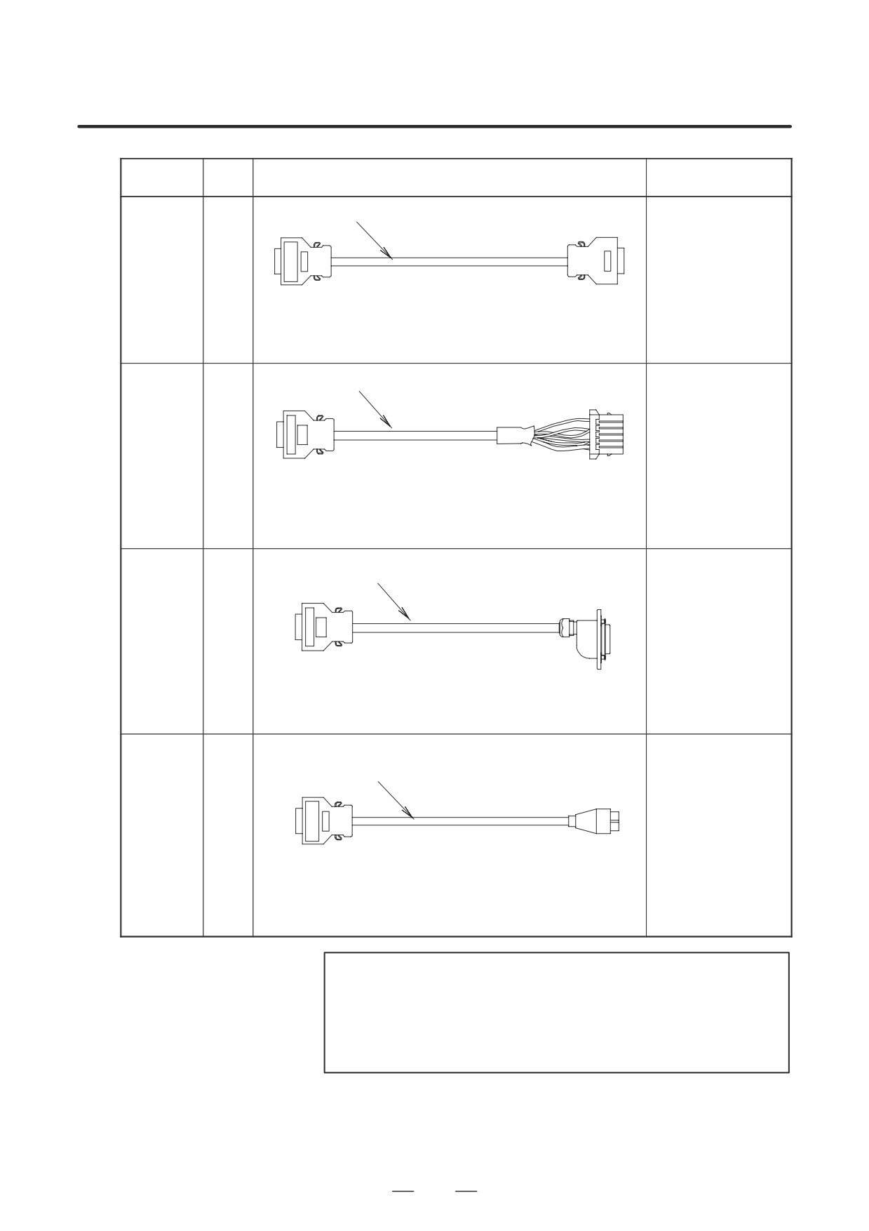
Twisted pair unified shield 10-pair 0.09mm2 (7/0.127) (Note 1)
SPM
(Interface
K12
between NC
and SPM)
NC side (JA7A)
SPM side (JA7B)
HONDA connector
HONDA connector
Connector : PCR-E20FA
Connector : PCR-E20FA
Housing
: PCR-V20LA
Housing
: PCR-V20LA
Composite 16-core unified
6-core 0.5mm2 (20/0.18)
shield cable
5-pair 0.18mm2 (7/0.18) (Note 2)
PSM
(For pulse
A06B-6078-K811
generator,
K14
(Cable length : 7m)
Built-in
sensor)
SPM side (JY2)
Motor side
HIROSE connector
AMP connector
Connector : FI40B-20S
Housing : 178289-6
Housing
: FI-20-CV5
Connector
:
1-175217-2
Composite 16-core unified
6-core 0.5mm2 (20/0.18)
shield cable
5-pair 0.18mm2 (7/0.18) (Note 2)
α0.5
(For pulse
generator,
K14
Built-in
sensor)
SPM side (JY2)
Motor side
HIROSE connector
Connector kit :
Connector : FI40B-20S
A06B-6050-K110
Housing
: FI-20-CV5
Composite 12-core unified
6-core 0.5mm2 (20/0.18)
shield cable
3-pair 0.18mm2 (7/0.18) (Note 3)
SPM
(For
A06B-6078-K813
K15
magnetic
(Cable length : 7m)
sensor)
SPM side (JY3)
Metal receptacle on
HIROSE connector
megnetic sensor side
Connector : FI40-2015S
Housing
: FI-20-CV
NOTE
1
FANUC’S specification (Material only) :
A66L-0001-0284#10P
2
FANUC’S specification (Material only) : A66L-0001-0368
3
FANUC’S specification (Material only) : A66L-0001-0286
640
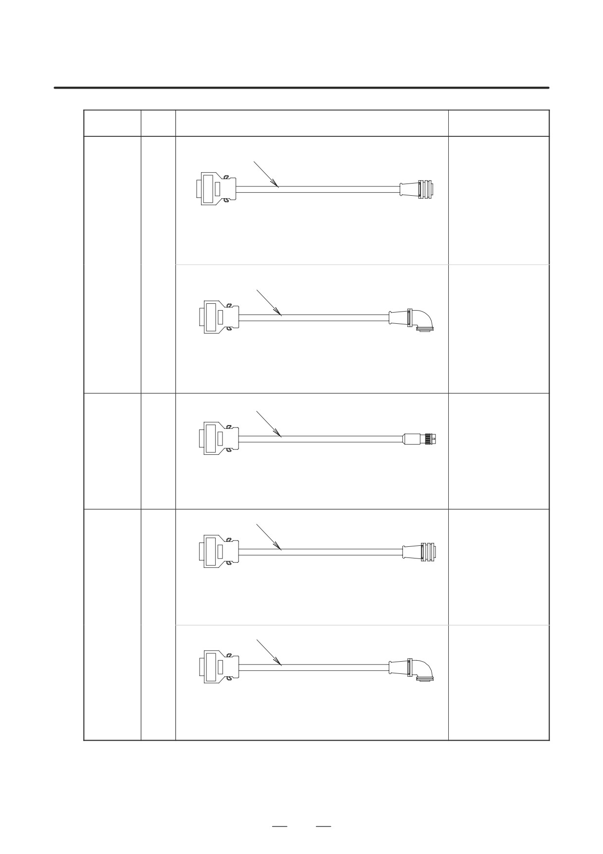
B-65162E/03
APPENDIX
F. SPECIFICATIONS OF CABLES
Sym-
FANUC specification
Use
Specification
bol
(complete cable)
Composite 12-core unified
6-core 0.5mm2 (20/0.18)
shield cable
3-pair 0.18mm2 (7/0.18) (Note 3)
A06B-6078-K814
(Cable length : 7m)
SPM side (JY3)
Position coder side
HIROSE connector
Connector :
Connector : FI40-2015S
MS3106B 20-29S
SPM
Housing
: FI-20-CV
Cable clamp :
MS3057-12A
(For
K16
Position
Composite 12-core unified
6-core 0.5mm2 (20/0.18)
coder)
shield cable
3-pair 0.18mm2
(7/0.18) (Note 5)
A06B-6078-K815
(Cable length : 7m)
SPM side (JY3)
Position coder side
HIROSE connector
Connector :
Connec-
MS3108B 20-29S
tor
: FI40-2015S
Cable clamp :
Housing
: FI-20-CV
MS3057-12A
Twisted pair unified shield 10-pair 0.18mm2 (7/0.18) (Note 4)
SPM
(For high-
A06B-6078-K816
resolution
K18
(Cable length : 7m)
magnetic
pulse coder)
SPM side (JY5)
Pre-amplifier side
HIROSE connector
HIROSE connector
Connector : FI40B-20S
HR22-12WTPA-20S
Housing
: FI-20-CV5
Twisted pair unified shield 10-pair 0.18mm2 (7/0.18) (Note 4)
A06B-6078-K817
(Cable length : 7m)
SPM side (JY4)
Position coder side
HIROSE connector
Connector :
Connector : FI40B-20S
MS3106B 20-29S
SPM
Housing
: FI-20-CV5
Cable clamp :
(For High-
MS3057-12A
resolution
K31
position
Twisted pair unified shield 10-pair 0.18mm2 (7/0.18) (Note 4)
coder)
A06B-6078-K818
(Cable length : 7m)
SPM side (JY4)
Position coder side
HIROSE connector
Connector :
Connector : FI40B-20S
MS3108B 20-29S
Housing
: FI-20-CV5
Cable clamp :
MS3057-12A
641
F. SPECIFICATIONS OF CABLES
APPENDIX
B-65162E/03
NOTE
1
FANUC’S specification (Material only) :
A66L-0001-0284#10P
2
FANUC’S specification (Material only) : A66L-0001-0368
3
FANUC’S specification (Material only) : A66L-0001-0286
4
FANUC’S specification (Material only) : A66L-0001-0367
642
G. SERVO AMPLIFIER NOISE
B-65162E/03
APPENDIX
PROTECTION
SERVO AMPLIFIER NOISE PROTECTION
G
This appendix describes how noise is generated when a servo motor or
spindle motor is driven by a servo amplifier, and also describes
countermeasures required for devices affected by noise.
While referring to this appendix, the user should pay careful attention to
noise protection when installing the machine.
643
G. SERVO AMPLIFIER NOISE
PROTECTION
APPENDIX
B-65162E/03
G.1
SERVO AMPLIFIER
NOISE GENERATION
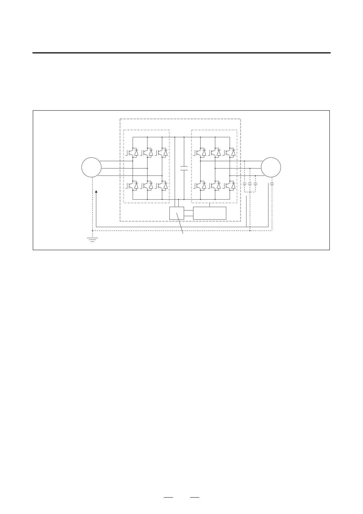
Fig. G.1 is a schematic diagram of a servo amplifier.
Converter section
Inverter section
Power
Motor
supply
Control
circuit
Noise current i
Control power supply
Fig.G.1 Schematic Diagram of Servo Amplifier
The servo amplifier converts alternating current to direct current in the
converter section, and exercises variable motor speed control by PWM
control based on switching by the six transistors in the inverter section.
Switching noise is generated by the six transistors turning on and off at
high speed. Each time a transistor is turned on or off, noise current (i)
flows to ground through stray capacitance (C) between the cable or motor
and ground. The value of this noise current (i) depends on stray
capacitance (C) and transistor switching speed (dV/dt), as follows:
i = C dV/dt
The frequency band of this noise is about 30 to 40 MHz. So, a device
using low frequencies (such as an AM radio) is affected by this noise.
However, FM radios and TV sets, which use higher frequencies, are not
normally affected by this noise.
As described above, noise is generated by the transistor switching that is
performed when the motor is driven.
In addition, when a servo amplifier performs power regeneration when a
motor decelerates (rotation energy is fed back to the power supply during
deceleration), voltage variations caused by current phase commutation at
regeneration can affect the operation of a device that shares that power
supply.
644
G. SERVO AMPLIFIER NOISE
B-65162E/03
APPENDIX
PROTECTION
Noise generated by a servo amplifier are classified into the three major
G.2
types described below.
TYPES OF NOISE
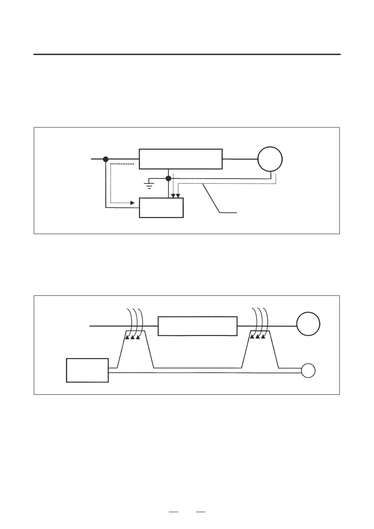
(1) Conductive Noise
Noise generated by a servo amplifier travels through a conductor such as
a run wire, and affects a device connected to the same power supply.
Power supply
Servo amplifier
Motor
Electronic
device
Noise can travel through a shared
ground wire.
Fig.G.2 (a) Conductive Noise
(2) Induced Noise
Noise is induced when a signal line or a line from a nearby device runs
near a line carrying a noise current.
Motor
Power supply
Servo amplifier
Sensor
Signal line
Electronic
device
Fig.G.2 (b) Electromagnetically Induced Noise
645
G. SERVO AMPLIFIER NOISE
PROTECTION
APPENDIX
B-65162E/03
Motor
Power supply
Servo amplifier
Sensor
Signal line
Electronic
device
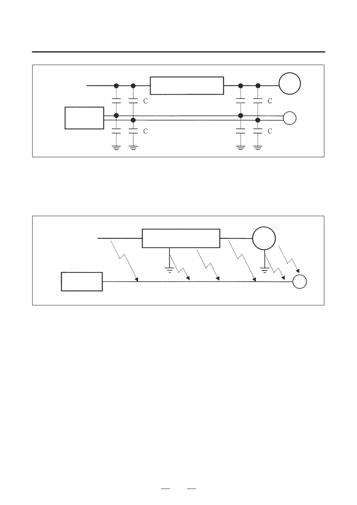
Fig.G.2 (c) Electrostatically Induced Noise
(3) Radiation Noise
Noise generated in a servo amplifier is radiated into the surroundings,
with a power line acting as an antenna.
Power supply
Servo amplifier
Motor
Electronic
device
Sensor
Fig.G.2 (d) Radiation Noise
Noise travels in many different ways, and affects the system to various
extents, depending on the system configuration.
646
G. SERVO AMPLIFIER NOISE
B-65162E/03
APPENDIX
PROTECTION
Present-day technology cannot eliminate noise completely. So,
G.3
cost-effective measures must be applied, depending on the level of the
NOISE PROTECTION
noise and the status of the installation.
G.3.1
If a noise problem is detected after installation, more costs may be incurred
to solve the problem. So, the following precautions must be applied:
Precautions to be
Applied Prior to
1
Separate power lines and motor power lines from signal lines.
Installation
2
Contain power lines and motor power lines in a metallic conduit.
3
Perform appropriate grounding installation including grounding
wire connections. (This also serves as a measure against electric
shock due to leakage currents.)
4
Grounding wires should be as thick and short as possible.
The electric installation standard defines types of grounding as follows:
Type of grounding
Application
Ground resistance
Class-3 grounding
300VAC or less
100Ω or less
Special class-3 grounding
300VAC to 600VAC
10Ω or less
G.3.2
Noise-related measures including those for devices affected by noise,
must be applied from the viewpoint of the entire system.
Measures
(1)
Measures to be applied to a device affected by noise
1
Separate the power lines and motor power lines from the signal
lines to minimize the influence of noise.
2
Separate the power supply system to eliminate any noise
propagation path.
3
Run the signal lines through ferrite core beads to maximize the
impedance against noise.
4
Employ line filters and shielding wires for the signal lines to
protect against noise.
(2)
Measures to be applied to a noise source
1
Reduce the level of noise by installing a noise protective device
such as a noise filter.
2
Confine noise by running the lines in metallic conduits or by
using shielding wires.
3
Eliminate any noise propagation path by using an insulating
transformer.
(3)
Measures specific to each type of noise
The types of noise are described in G.2 above. Different measures
should be taken for each type of noise. The measures and their effects
depend on the environment (power supply, electromagnetic wave
strength), machine operating status, machine anti-noise properties,
and so forth.
647
G. SERVO AMPLIFIER NOISE
PROTECTION
APPENDIX
B-65162E/03
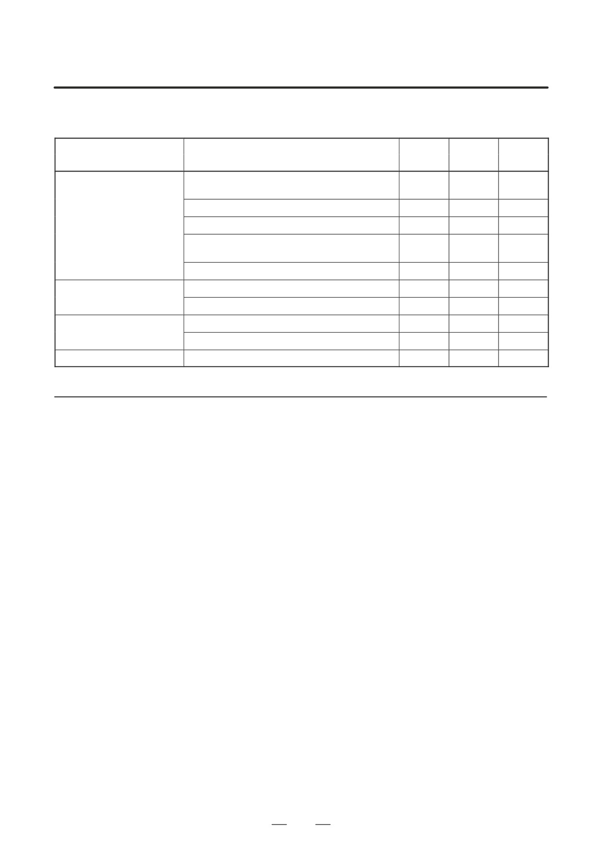
Apply the most efficient measures as described in Table G.3.2
Table.G.3.2 Measures Specific to Each Type of Noise
Type of noise
Conduc-
Induced
Radiation
Measures
tive noise
noise
noise
Separation of power lines and motor power lines from
f
f
signal lines
Use of metallic conduits
f
f
Wiring and grounding
Elimination of parallel wiring
f
Employing shielded wires for power lines and motor
f
power lines
Secure grounding
f
Line filter
f
f
Noise protective device
(at noise source)
Insulating transformer
f
f
Running signal lines through ferrite core beads
f
f
Noise protective device
(on devices affected by noise)
Employing shielded wires for signal lines
f
f
Others
Power system separation
f
G.3.3
Examples of Noise
Protection
(1)
AM Radio
<<Symptoms>>
When a motor is activated, radios in the plant pick up noise, such that
the radio output becomes inaudible.
<<Possible causes>>
Radiation noise from the motor power line connected to a servo
amplifier is being picked up by the radios.
<<Measures>>
1
Install a noise filter (LC filter) on the power supply.
2
Install a capacitor between each input phase and ground.
<<Notes>>
D The measures described above may prove ineffective in some
areas, such as dense residential areas and mountain areas, where
radio signals are weak.
D When installing a noise filter, minimize the length of the wiring
between the filter and servo amplifier.
(2)
FM Radio
<<Symptoms>>
When the machine is operated, radios in the neighborhood are
affected by noise. A radio in a car parked outside the plant also picks
up noise.
648
G. SERVO AMPLIFIER NOISE
B-65162E/03
APPENDIX
PROTECTION
<<Possible causes>>
The transformer on a utility pole is shared by neighbors, and noise is
being radiated from the power supply wiring. Noise may also be
conducted through the power supply line.
<<Measures>>
1
Install a noise filter (LC filter) on the power supply.
2
Feed power to the neighbors from a separate utility pole.
<<Notes>>
D When installing a noise filter, minimize the length of the wiring
between the filter and servo amplifier.
(3)
Refrigerator
<<Symptoms>>
When the spindle rotation is decelerated, the motor of a refrigerator
in the neighborhood makes an abnormal sound.
<<Possible causes>>
The transformer on a utility pole is shared by neighbors, and voltage
distortion is caused by power regeneration at spindle deceleration.
<<Measures>>
1
Feed power to the neighbors from a separate utility pole.
2
Review the power supply capacity.
<<Notes>>
D A plant located in a dense residential area often takes its power
from a utility pole that also supplies power to neighboring houses
(light power sharing), such that the power supply capacity of the
system may be insufficient. In such a case, a larger power
distortion may result, thus affecting the power being fed to
neighboring houses.
(4)
Telephone
<<Symptoms>>
When the machine is operated, the telephone of a house across the
street is affected by noise.
<<Possible causes>>
When a high-frequency current from the servo amplifier or motor
returns through the ground of the transformer of the utility pole, it
flows through the ground shield of the telephone line, generating
noise by electrostatic induction.
<<Measures>>
1
Feed power to the neighbors from a separate utility pole.
2
Insert a capacitor on the grounding wire on the servo amplifier
power supply side.
<<Notes>>
D Noise consists of voice frequency components, so that a noise
filter (LC filter) may have no effect.
D Inserting a capacitor on a grounding wire increases the leakage
current, so that the ground fault interrupter may function.
649
G. SERVO AMPLIFIER NOISE
PROTECTION
APPENDIX
B-65162E/03
(5) FAX
<<Symptoms>>
When the machine is operated, e telephone within the plant picks up
noise, or a facsimile machine of a neighboring firm is disabled. The
telephone within the plant uses 100 V; when the 100-V supply is
removed, normal telephone communications are resumed.
<<Possible causes>>
The transformer of a utility pole is shared, so that conductive noise
is conveyed through the power line. Or, noise may be induced in the
wiring as in the case of (4) above.
<<Measures>>
1
Feed power to the neighbors from a separate utility pole.
2
Install an insulating transformer (noise cut transformer) in the
power supply.
<<Notes>>
D As with (4) above, a noise filter (LC filter) may have no effect on
low-frequency noise.
G.3.4
As mentioned above, the protective measures and devices depend on the
types of noise, noise sources, and the level of the noise. Noise-preventive
Noise-preventive
devices are outlined below. The user should apply measures that are
Devices
appropriate for the situation. For details including the specifications of
these devices, contact the corresponding manufacturer. The contact for
each manufacturer is listed below.
Okaya Electric Industries : Sales Division
03(3424)8126
Soshin Electric
: EMC Division 03(3775)9112
TDK
: Electronic Device Division
03(5201)7229
Tokin
: Sales Promotion Division
03(3475)6818
Fuji Electric
: Sales Group, Device Division 03(3211)9288
(1)
Noise Filter
A noise filter is installed between a power supply and servo amplifier to
reduce high-frequency noise superimposed on supply voltage (noise
terminal voltage). A noise filter is useful for the AM radio frequency
band.
Example products:
Okaya Electric
:
3SUP-H/3SUP-D series
Soshin Electric : NF3000/HF3000 series
TDK
: ZRCT/ZRGT series
Tokin
: LH-3/LH-4 series
(2)
Capacitor
A capacitor is directly connected to a servo amplifier to reduce radiation
noise from the power line. When compared with a noise filter, a capacitor
offers poorer attenuation characteristics, but is often more effective,
depending on the electromagnetic wave status. Considering the leakage
current, select a ground fault interrupter.
650
G. SERVO AMPLIFIER NOISE
B-65162E/03
APPENDIX
PROTECTION
Example products
:
Okaya Electric
:
3XYB-105 104
Soshin Electric
: LW3/LY3 series
(3) Zero-phase reactor
A zero-phase reactor is installed between a power supply and servo
amplifier to reduce the amount noise being radiated from the power line.
Example product:
Soshin Electric : RC series
(4) Noise Cut Transformer
A noise cut transformer is installed between a power supply and device.
This transformer is used to reduce the amount of radiation noise (low
frequency) being conveyed through a power line or ground wire.
Example product:
Fuji Electric
: FFT series
651
G. SERVO AMPLIFIER NOISE
PROTECTION
APPENDIX
B-65162E/03
G.4
OTHERS
Harmonics and noise
A harmonic has an integral multiple of a fundamental frequency (50/60
Hz), usually, up to several kHz; a higher frequency (several kHz or higher)
is referred to as noise.
In many cases, noise is generated from an inverter section, while
harmonics are generated from a converter section. Accordingly, these
differ in the problems they incur and the corresponding countermeasures.
For harmonics, a harmonics suppression guideline has been established.
652