FANUC Series 0i-MODEL C, Series 0i Mate-MODEL C. MAINTENANCE MANUAL - page 23
D. FSSB START-UP PROCEDURE/
MATERIALS
APPENDIX
B-64115EN/02
When the following parameters are set, each axis can be set manually:
D.4
No.1902#0=1
MANUAL SETTING 2
No.1902#1=0
When performing manual setting, set parameter Nos. 1023, 1905, 1910
through 1919, 1936, and 1937, fully understanding their functions.
#7
#6
#5
#4
#3
#2
#1
#0
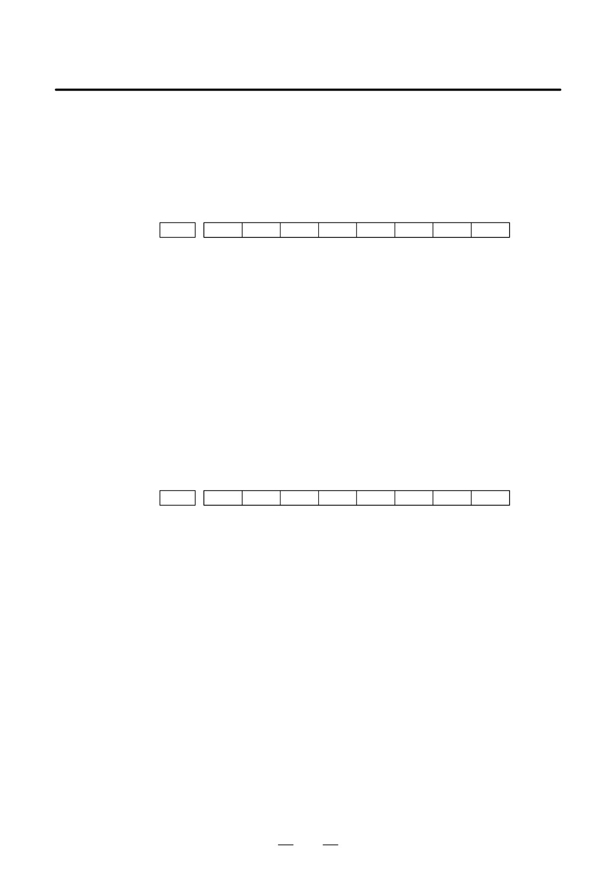
1902
ASE
FMD
[Data type]
Bit
#0 (FMD)
The FSSB setting mode is:
0 : Automatic setting mode.
(When data including the relationship
between axes and amplifiers is set on the FSSB setting screen,
parameter Nos. 1023, 1905, 1910 through 1919, 1936, and 1937 are
automatically set.)
1 : Manual setting 2 mode. (Parameter Nos. 1023, 1905, 1910 through
1919, 1936, and 1937 are set manually.)
#1 (ASE)
When the FSSB setting mode is the automatic setting mode (when bit 0 of
parameter No. 1902 = 0), automatic setting is:
0 : Not completed.
1 : Completed.
(This bit is automatically set to
1 when automatic setting is
completed.)
#7
#6
#5
#4
#3
#2
#1
#0
1905
PM2
PM1
FSL
[Data type] Bit axis
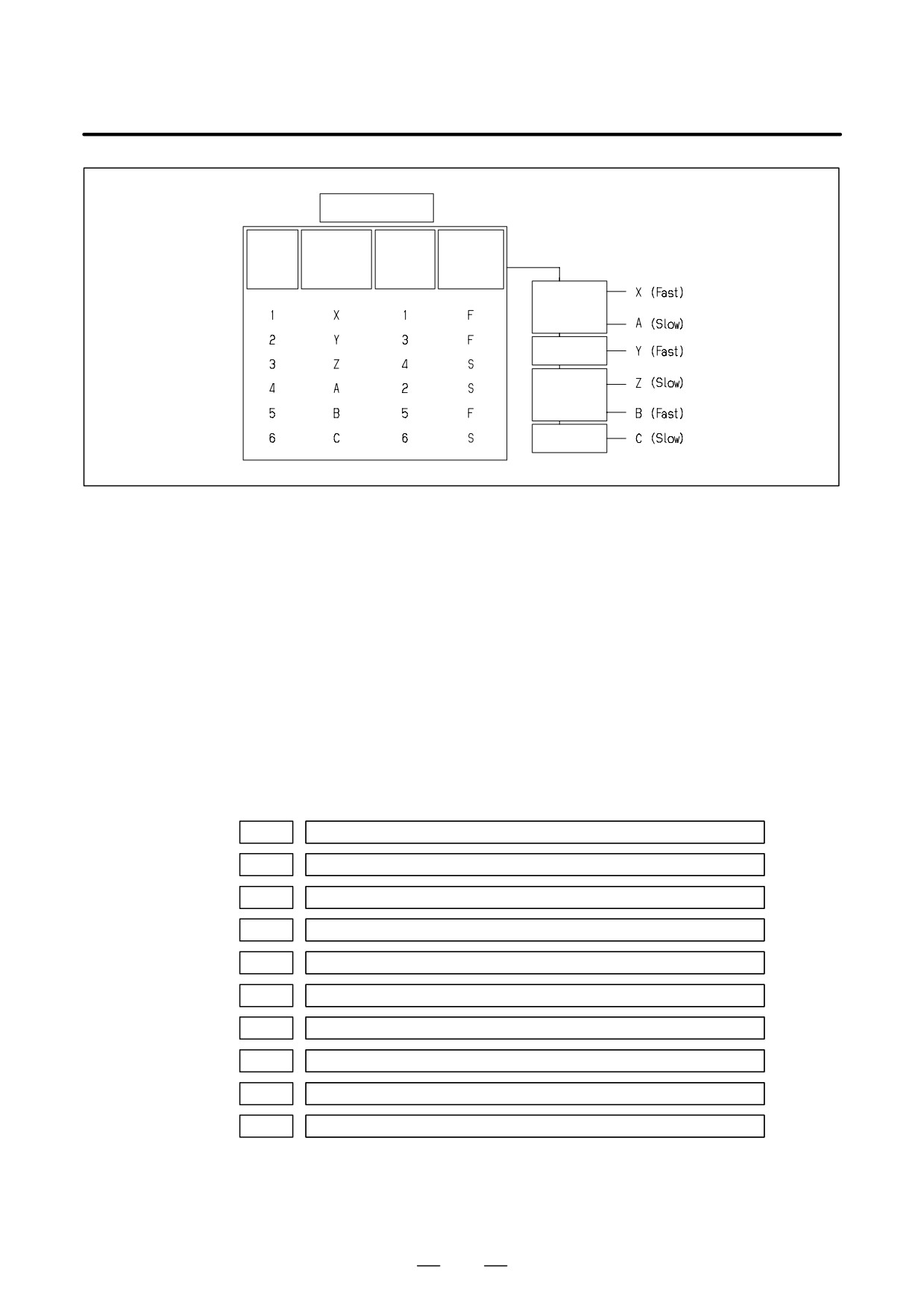
#0 (FSL) The type of interface between servo amplifiers and servo software is:
0 : Fast type.
1 : Slow type.
Two servo data transfer interface types are available: the fast type and
slow type.
Set this bit so that the following conditions are satisfied:
D When a 1-axis amplifier is used, both of the fast and slow types can
be used.
D When a 2-axis amplifier is used, the fast type must not be used for
both axes. The slow type can be used for both axes.
D When a 3-axis amplifier is used, the first and second axes must
satisfy the condition for a 2-axis amplifier, and the third axis must
satisfy the condition for a one-axis amplifier.
D With an axis for which an odd number is set in parameter No. 1023,
the fast type must be used. The slow type can also be used,
however, for an EGB workpiece axis, learning-control axis,
high-speed current loop axis, and high-speed interface axis.
D Only the slow type can be used with an axis for which an even
number is set in parameter No. 1023. (Be sure to set this bit to 1).
640
D. FSSB START-UP PROCEDURE/
B-64115EN/02
APPENDIX
MATERIALS
CNC
Con-
Program
Servo
Interface
trolled
axis name
axis No.
type
axis No.
No.1020
No.1023
Fast/Slow
2-axis AMP
1-axis AMP
2-axis AMP
1-axis AMP
#6 (PM1)
The first separate detector interface unit is:
0 : Not used.
1 : Used.
#7 (PM2)
The second separate detector interface unit is:
0 : Not used.
1 : Used.
This parameter is automatically set by data input on the FSSB setting
screen when the FSSB setting mode is the automatic setting mode (when
bit 0 of parameter No. 1902 = 0). When the manual setting 2 mode is used
(when bit 0 of parameter No. 1902 = 1), be sure to enter necessary data
directly.
When a separate detector interface unit is used, connector numbers
(parameter Nos. 1936 and 1937) need to be set.
PRM
1910
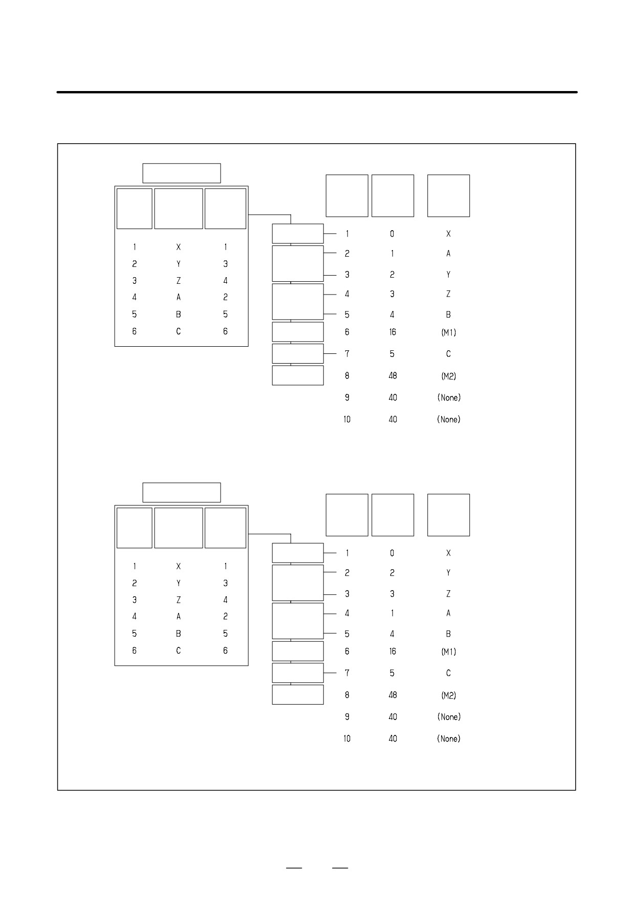
Address conversion table value for slave 1 (ATR)
PRM
1911
Address conversion table value for slave 2 (ATR)
PRM
1912
Address conversion table value for slave 3 (ATR)
PRM
1913
Address conversion table value for slave 4 (ATR)
PRM
1914
Address conversion table value for slave 5 (ATR)
PRM
1915
Address conversion table value for slave 6 (ATR)
PRM
1916
Address conversion table value for slave 7 (ATR)
PRM
1917
Address conversion table value for slave 8 (ATR)
PRM
1918
Address conversion table value for slave 9 (ATR)
PRM
1919
Address conversion table value for slave 10 (ATR)
[Data type]
Byte
[Valid data range]
0 to 7, 16, 40, 48
Set an address conversion table value for each of slave 1 through 10.
641
D. FSSB START-UP PROCEDURE/
MATERIALS
APPENDIX
B-64115EN/02
The slave is the generic name of a servo amplifier or separate detector
interface unit connected to the CNC via an FSSB optical cable. The
numbers from 1 to 10 are assigned to the slaves in ascending order; a
younger number is assigned to a slave that is closer to the CNC. A 2-axis
amplifier consists of two slaves, and a 3-axis amplifier consists of three
slaves. Set each of the parameters as described below according to which
of the three cases is applicable: the slave is an amplifier, the slave is a
separate detector interface unit, or there is no slave.
` When the slave is an amplifier:
Set a value obtained by subtracting 1 from the setting of parameter No.
1023 for the axis to which the amplifier is assigned.
` When the slave is a separate detector interface unit:
S For the first separate detector interface unit (closest to the CNC),
set 16.
S For the second separate detector interface unit (farthest from the
CNC), set 48.
` When there is no slave:
Set 40.
These parameters are automatically set by data input on the FSSB setting
screen when the FSSB setting mode is the automatic setting mode (when
bit 0 of parameter No. 1902 = 0). When the manual setting 2 mode is used
(when bit 0 of parameter No. 1902 = 1), be sure to enter necessary data
directly.
642
D. FSSB START-UP PROCEDURE/
B-64115EN/02
APPENDIX
MATERIALS
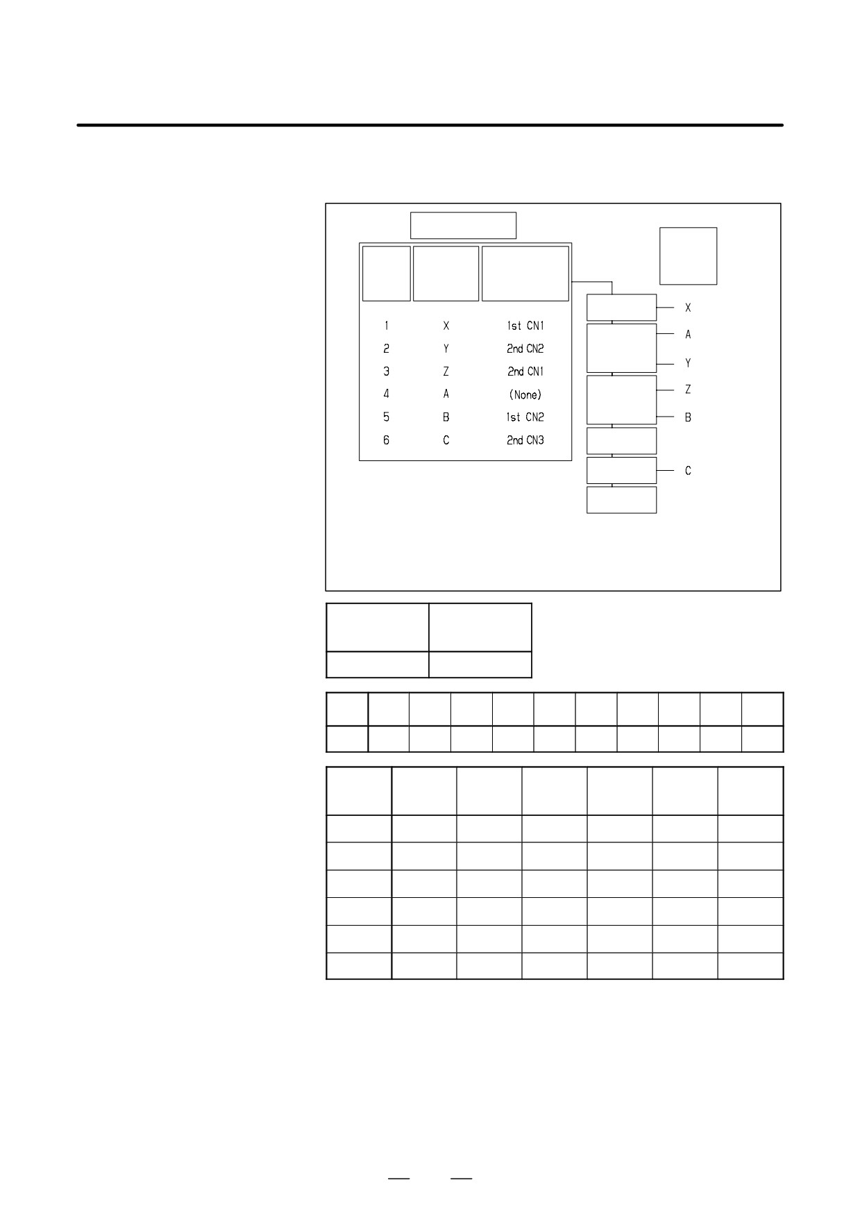
` Axis configuration and example of parameter setting
CNC
Slave
ATR
No.
No.1910
AXIS
Control
Program
Servo
axis
axis name
axis No.
to 1919
No.
No.1020
No.1023
1 axis AMP
L-axis
2 axis AMP
M-axis
L-axis
2 axis AMP
M-axis
M1
1 axis AMP
M2
Note) M1/M2 : Separate detector interface
Note) M1/M2 : unit 1 st/2 nd
CNC
Slave
ATR
No.
No.1910
AXIS
Control
Program
Servo
axis
axis name
axis No.
to 1919
No.
No.1020
No.1023
1 axis AMP
L-axis
2 axis AMP
M-axis
L-axis
2 axis AMP
M-axis
M1
1 axis AMP
M2
Note) M1/M2 : Separate detector interface
Note) M1/M2 : unit 1 st/2 nd
643
D. FSSB START-UP PROCEDURE/
MATERIALS
APPENDIX
B-64115EN/02
PRM
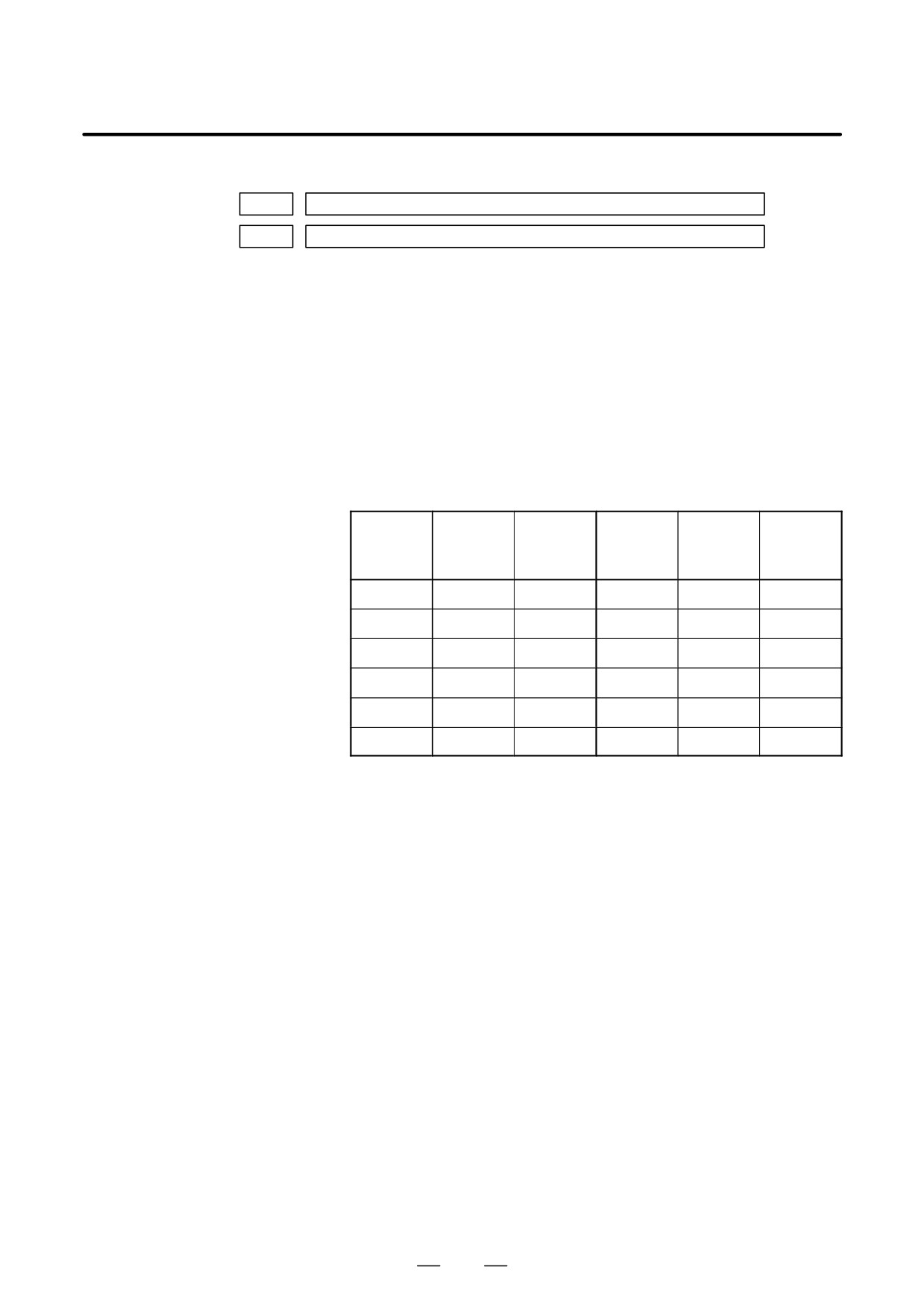
1936
Connector number for the first separate detector interface unit
PRM
1937
Connector number for the second separate detector interface unit
[Data type]
Byte axis
[Valid data range]
0 to 7
When using a pulse module, set a value obtained by subtracting 1 from
the pulse module connector number for each axis. That is, for connector
numbers 1 to 8, set the values 0 to 7. Moreover, set bits 6 and 7 of
parameter No. 1905. Set 0 for an axis for which no pulse module is used.
The user can freely determine which connector to use for which axis. Use
connector numbers, starting with younger numbers. For example,
connector number 4 cannot be used without using connector number 3.
Example:
Con-
First con-
Second
No.1905
trolled
nector
connector
No.1936
No.1937
(#7,#6)
axis
number
number
X
1
Not used
0
0
0,1
Y
Not used
2
0
1
1,0
Z
Not used
1
0
0
1,0
A
Not used
Not used
0
0
0,0
B
2
Not used
1
0
0,1
C
Not used
3
0
2
1,0
These parameters are automatically set by data input on the FSSB setting
screen when the FSSB setting mode is the automatic setting mode (when
bit 0 of parameter No. 1902 = 0). When the manual setting 2 mode is used
(when bit 0 of parameter No. 1902 = 1), be sure to enter necessary data
directly.
644
D. FSSB START-UP PROCEDURE/
B-64115EN/02
APPENDIX
MATERIALS
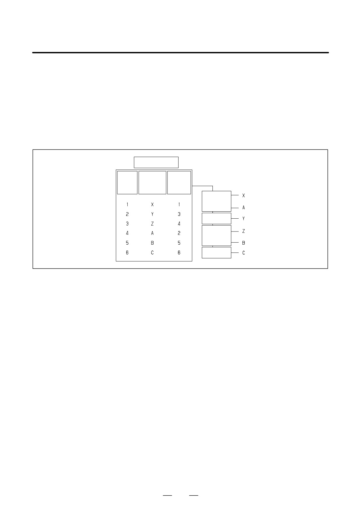
` Axis configuration and example of parameter setting in the manual
setting 2 mode
CNC
Control
Program
Pulse Module
AXIS
axis
axis name
Connector
No.
No.1020
1 axis AMP
L-axis
2 axis AMP
M-axis
L-axis
2 axis AMP
M-axis
M1
1 axis AMP
M2
Note) M1/M2 : Separate detector interface
Note) M1/M2 : unit 1 st/2 nd
1902#0
No.
FSBMD
1
No.
1910
1911
1912
1913
1914
1915
1916
1917
1918
1919
0
1
2
3
4
16
5
48
40
40
1905#0
1905#6
1905#7
No.
1023
1936
1937
FSBSL
FSBM1
FSBM2
X
1
0
1
0
0
0
Y
3
0
0
1
0
1
Z
4
1
0
1
0
0
A
2
1
0
0
0
0
B
5
0
1
0
1
0
C
6
1
0
1
0
2
645
D. FSSB START-UP PROCEDURE/
MATERIALS
APPENDIX
B-64115EN/02
When the following parameters are set, manual setting 1 is enabled:
D.5
Bit 0 of No. 1092 = 0
MANUAL SETTING 1
Bit 1 of No. 1902 = 0
Nos. 1910 through 1919 = 0 (all set to 0)
In manual setting 1, a setting is made at power-on so that the value set in
parameter No. 1023 is assumed to be a slave number. That is, an axis for
which the value of parameter No. 1023 is 1 is connected to the amplifier
closest to the CNC. An axis for which the value of parameter No. 1023
is 2 is connected to the amplifier next closest to the CNC.
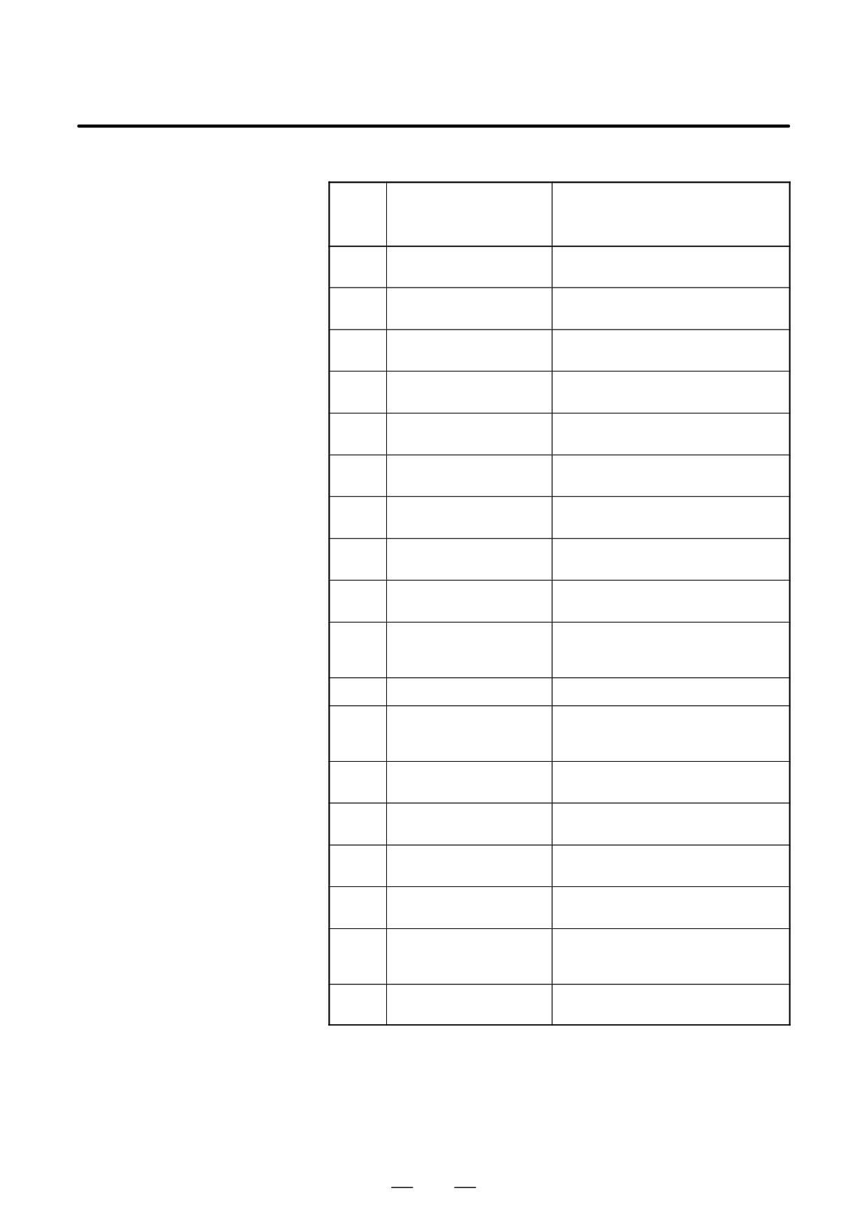
CNC
Control
Program
Servo
axis
axis name
axis No.
No.
No.1020
No.1023
2-axis AMP
1-axis AMP
2-axis AMP
1-axis AMP
Note that some functions and settings cannot be used in manual setting
1 as described below.
D No separate detector interface unit can be used.
This means that no separate position detector can be used.
D Set sequential numbers in parameter No. 1023.
For example, 3 cannot be set for an axis without setting 2 for any axis.
D The following servo functions cannot be used:
- High-speed current loop
646
D. FSSB START-UP PROCEDURE/
B-64115EN/02
APPENDIX
MATERIALS
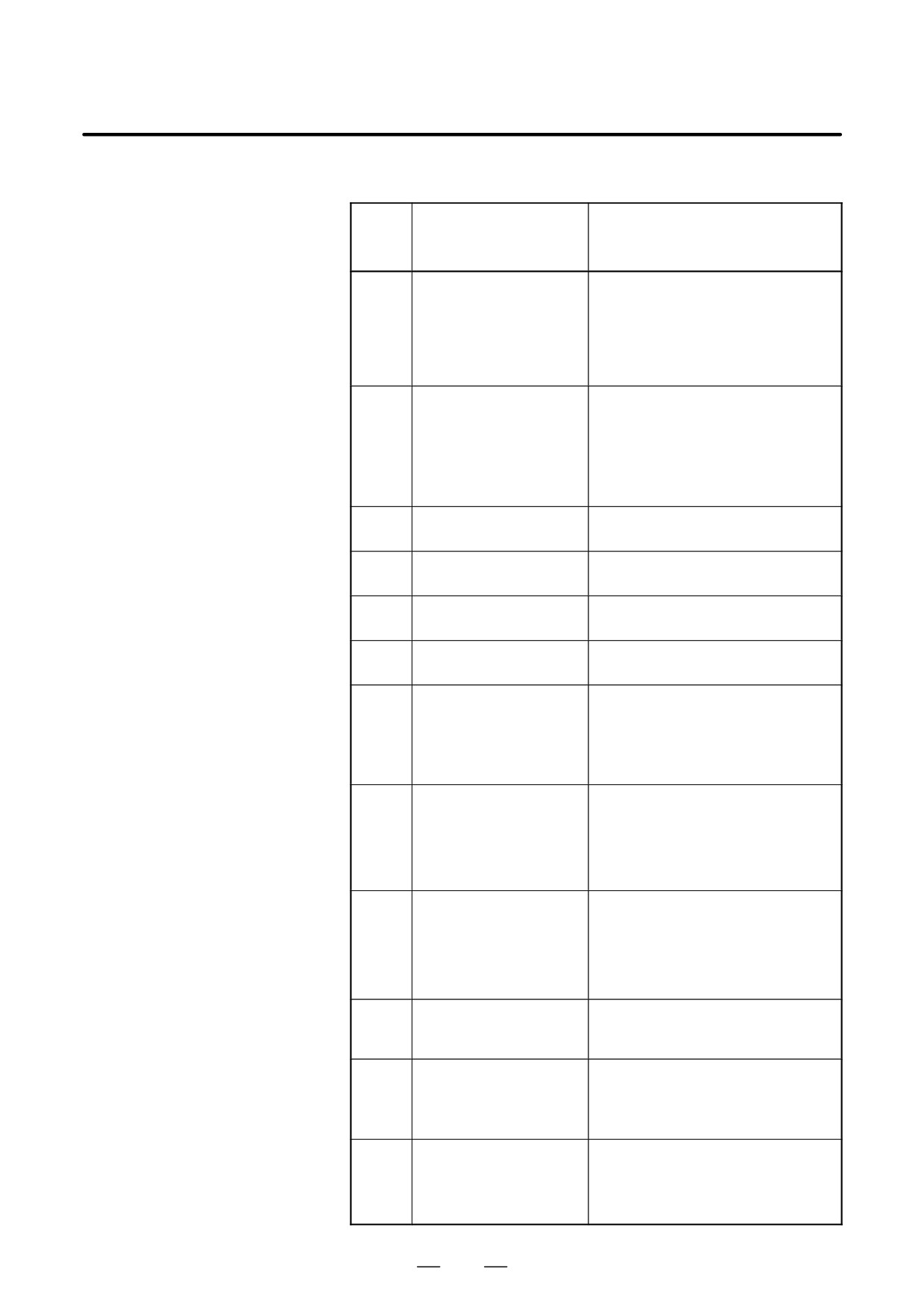
Alarms related to pulse coders
D.6
ALARMS
NC
alarm
Message
Description
No.
360
n AXIS : ABNORMAL
A checksum error occurred in the built-in
CHECKSUM (INT)
pulse coder.
361
n AXIS : ABNORMAL PHASE
A phase data error occurred in the built-in
DATA (INT)
pulse coder.
362
n AXIS : ABNORMAL
A rotation speed count error occurred in the
REV.DATA (INT)
built-in pulse coder.
363
n AXIS : ABNORMAL CLOCK
A clock error occurred in the built-in pulse
(INT)
coder.
364
n AXIS : SOFT PHASE
The digital servo software detected invalid
ALARM (INT)
data in the built-in pulse coder.
365
n AXIS : BROKEN LED (INT)
An LED error occurred in the built-in pulse
coder.
366
n AXIS : PULSE MISS (INT)
A pulse error occurred in the built-in pulse
coder.
367
n AXIS : COUNT MISS (INT)
A count error occurred in the built-in pulse
coder.
368
n AXIS : SERIAL DATA ER-
Communication data from the built-in pulse
ROR (INT)
coder cannot be received.
369
n AXIS : DATA TRANS. ER-
A CRC or stop bit error occurred in the com-
ROR (INT)
munication data being received from the
built-in pulse coder.
380
n AXIS : BROKEN LED (EXT)
The LED of separate detector is erroneous.
381
n AXIS : ABNORMAL PHASE
A phase data error occurred in the separate
linear scale.
(EXT LIN)
382
n AXIS : COUNT MISS (EXT)
A pulse error occurred in the separate de-
tector.
383
n AXIS : PULSE MISS (EXT)
A count error occurred in the separate de-
tector.
384
n AXIS : SOFT PHASE
The digital servo software detected invalid
ALARM (EXT)
data in the separate detector.
385
n AXIS : SERIAL DATA ER-
Communication data from the separate de-
ROR (EXT)
tector cannot be received.
386
n AXIS : DATA TRANS. ER-
A CRC or stop bit error occurred in the com-
ROR (EXT)
munication data being received from the
separate detector.
387
n AXIS : ABNORMAL EN-
An error occurs in the separate detector. For
CODER (EXT)
details, contact the manufacturer of the scale.
647
D. FSSB START-UP PROCEDURE/
MATERIALS
APPENDIX
B-64115EN/02
Alarms related to servo amplifiers
NC
alarm
Message
Description
No.
432
n AXIS : CNV. LOW VOLT
1) PSM: Control power voltage has
CONTROL
dropped.
2) PSMR: The control power supply voltage
has dropped.
3) β series SVU: The control power supply
voltage has dropped.
433
n AXIS : CNV. LOW VOLT DC
1) PSM: The DC link voltage has dropped.
LINK
2) PSMR: The DC link voltage has dropped.
3) α series SVU: The DC link voltage has
dropped.
4) β series SVU: The DC link voltage has
dropped.
434
n AXIS : INV. LOW VOLT
SVM: The control power supply voltage has
CONTROL
dropped.
435
n AXIS : INV. LOW VOLT DC
SVM: The DC link voltage has dropped.
LINK
436
n AXIS : SOFTTHERMAL
The digital servo software detected the soft
(OVC)
thermal state (OVC).
437
n AXIS : CNV. OVERCUR-
PSM: Overcurrent flowed into the input cir-
RENT POWER
cuit.
438
n AXIS : INV. ABNORMAL
1) SVM: The motor current is too high.
CURRENT
2) α series SVU: The motor current is too
high.
3) β series SVU: The motor current is too
high.
439
n AXIS : CNV. OVERVOLT
1) PSM: The DC link voltage is too high.
POWER
2) PSMR: The DC link voltage is too high.
3) α series SVU: The C link voltage is too
high.
4) β series SVU: The link voltage is too high.
440
n AXIS : CNV. EX DECEL-
1) PSMR: The regenerative discharge
ERATION POW.
amount is too large.
2) α series SVU: The regenerative dis-
charge amount is too large. Alternatively,
the regenerative discharge circuit is ab-
normal.
441
n AXIS : ABNORMAL CUR-
The digital servo software detected an ab-
RENT OFFSET
normality in the motor current detection cir-
cuit.
442
n AXIS : CNV. CHARGE
1) PSM: The spare discharge circuit of the
FAILURE
DC link is abnormal.
2) PSMR: The spare discharge circuit of the
DC link is abnormal.
443
n AXIS : CNV. COOLING FAN
1) PSM: The internal stirring fan failed.
FAILURE
2) PSMR: The internal stirring fan failed.
3) β series SVU: The internal stirring fan
failed.
648
D. FSSB START-UP PROCEDURE/
B-64115EN/02
APPENDIX
MATERIALS
NC
alarm
Message
Description
No.
444
n AXIS : INV. COOLING FAN
SVM: The internal stirring fan failed.
FAILURE
445
n AXIS : SOFT DISCON-
The digital servo software detected a broken
NECT ALARM
wire in the pulse coder.
446
n AXIS : HARD DISCON-
A broken wire in the built-in pulse coder
NECT ALARM
was detected by hardware.
447
n AXIS : HARD DISCON-
A broken wire in the separate detector was
NECT (EXT)
detected by hardware.
448
n AXIS : UNMATCHED
The sign of feedback data from the built-in
FEEDBACK ALARM
pulse coder differs from that of feedback
data from the separate detector.
449
n AXIS : INV. IPM ALARM
1) SVM: IPM (intelligent power module) de-
tected an alarm.
2) α series SVU: IPM (intelligent power
module) detected an alarm.
453
n AXIS : SPC SOFT DIS-
Software disconnection alarm of the α pulse
CONNECT ALARM
coder.
Turn off the power to the CNC, then remove
and insert the pulse coder cable. If this
alarm is issued again, replace the pulse
coder.
456
ILLEGAL CURRENT LOOP
The current control cycle settings (parame-
ter No. 2004, bit 0 of parameter No. 2003,
and bit 0 of parameter No. 2013) are incor-
rect. Possible problems are as follows.
- For the two axes whose servo axis
numbers (settings of parameter No.
1023) are an odd number followed by an
even number (a pair of axes 1 and 2 or
axes 5 and 6, for example), a different
current control cycle is set for each of
the axes.
- The requirements for slaves needed for
the set current control cycle, including
the number, type, and connection meth-
od of them, are not satisfied.
457
ILLEGAL HI HRV (250US)
Use of high-speed HRV is specified al-
though the current control cycle is 200 µs.
458
CURRENT LOOP ERROR
The current control cycle setting does not
match the actual current control cycle.
459
HI HRV SETTING ERROR
Of two axes having adjacent servo axis
numbers (parameter No. 1023), odd number
and even number, high-speed HRV control
can be performed for one axis and not for
the other.
649
D. FSSB START-UP PROCEDURE/
MATERIALS
APPENDIX
B-64115EN/02
Alarms related to servo amplifiers
NC
alarm
Message
Description
No.
460
n AXIS : FSSB DISCON-
FSSB communication was disconnected
NECT
suddenly. The possible causes are as fol-
lows:
1) The FSSB communication cable is dis-
connected or broken.
2) The power to the amplifier dropped sud-
denly.
3) The amplifier issued a low-voltage
alarm.
461
n AXIS : ILLEGAL AMP IN-
Both axes of a 2-axis amplifier were as-
TERFACE
signed to the fast type interface.
462
n AXIS : SEND CNC DATA
Because of an FSSB communication error, a
FAILED
slave could not receive correct data.
463
n AXIS : SEND SLAVE DATA
Because of an FSSB communication error,
FAILED
the servo system could not receive correct
data.
466
n AXIS : MOTOR/AMP COM-
The maximum current value of the amplifier
BINATION
does not match the maximum current value
of the motor.
467
n AXIS : ILLEGAL SETTING
The following servo functions are not en-
OF AXIS
abled even when an axis using a DSP ex-
clusively is set on the axis setting screen:
1) Learning control (bit 5 of parameter No.
2008 = 1)
2) High-speed current loop (bit 0 of param-
eter No. 2004 = 1)
3) High-speed interface axis (bit 4 of pa-
rameter No. 2005 = 1)
468
HI HRV SETTING ER-
Use of high-speed HRV is specified for a
ROR(AMP)
controlled axis of an amplifier which does
not support high-speed HRV.
650
D. FSSB START-UP PROCEDURE/
B-64115EN/02
APPENDIX
MATERIALS
P/S alarms
NC
alarm
Message
Description
No.
5134
FSSB : OPEN READY TIME
The FSSB did not become ready to open
OUT
duringinitialization.
5135
FSSB : ERROR MODE
The FSSB entered an error mode.
5136
FSSB : NUMBER OF AMPS
The number of amplifiers recognized by the
IS SMALL
FSSB is insufficient, compared with the
number of controlled axes.
5137
FSSB : CONFIGURATION
The FSSB detected a configuration error.
ERROR
5138
FSSB : AXIS SETTING NOT
Axis setting has not been performed in auto-
COMPLETE
matic setting mode. Perform axis setting
using the FSSB setting screen.
5139
FSSB : ERROR
The servo system could not be initialized
normally. The cause may be an optical
cable failure or incorrect connection with an
amplifier and other modules.
5197
FSSB : OPEN TIME OUT
The FSSB did not open when the CNC had
allowed the FSSB to open.
5198
FSSB : ID DATA NOT READ
The initial ID information for the amplifier
cannot be read because of a failure in the
temporary assignment.
5311
FSSB : ILLEGAL CONNEC-
A connection related to FSSB is illegal.This
TION
alarm is issued when either of the following
is found:
1
Two axes having adjacent servo axis
numbers (parameter No. 1023), odd
number and even number, are assigned
to amplifiers to which different FSSB
systems are connected.
2
The system does not satisfy the require-
ments for performing HRV control, and
use of two pulse modules connected to
different FSSB systems having different
FSSB current control cycles is speci-
fied.
651
D. FSSB START-UP PROCEDURE/
MATERIALS
APPENDIX
B-64115EN/02
D
MDI input is abnormal (each time data is entered, the power needs to
D.7
be turned off).
ACTIONS FOR
First, disconnect the optical cable of the NC, then turn off then on the
TROUBLE
power. Next, check the items below.
ENCOUNTERED AT
(A) Check parameter No. 1902.
START-UP TIME
Action: hen parameter
No. 1902 = 00000000, set the following:
No. 1905 = 00000000
Nos. 1910 through 1919 = 0
Action: hen parameter
No. 1902 = 00000001 or 00000010, set the following:
No. 1905 = Appropriate value
Nos. 1910 through 1919 = Appropriate value
(B) When bit 1 of parameter No. 1815 = 1, check parameter Nos.
1910 through 1919 to see if 16 or 48 is set.
Action: If neither 16 nor 48 is set, set bit 1 of No. 1815 to 1.
(C) Check if communication is open (the green LED is on).
Action: If communication is not open, check the power supply
for the amplifier and optical cable connection.
D
The separate detector can be recognized, but feedback pulses from the
separate detector are abnormal.
(A) Check parameter No. 1902.
Action: The setting of parameter
No. 1902 = 00000000 is incorrect. When parameter
No. 1902 = 00000001, set the following:
No. 1905 = 01000000 or 10000000
Nos. 1910 through 1919 = Appropriate value
Nos. 1936 and 1937 = Appropriate value
Action: When parameter No. 1902 = 00000010, set connector
numbers for M0 and M1 in axis setting on the FSSB
screen.
D
In axis setting on the FSSB screen, connector numbers for M1 and M2
cannot be set.
Action: Check the FSSB screen to see if separate detector interface
unit IDs are read correctly. If pulse module IDs are not read
correctly, check the separate detector interface unit
connections.
D
The settings on the FSSB screen are canceled when the power is turned
off then back on.
Action: After setting desired values, press soft key [SETING] on the
amplifier setting screen and axis setting screen.
D
P/S alarm 5138 “AXIS SETTING NOT COMPLETE” is issued.
Action: Automatic setting on the FSSB screen is not terminated
normally. Make settings correctly on the FSSB amplifier
setting screen and axis setting screen, and press soft key
[SETING] on both screens. At this time, be sure to make
settings on the amplifier setting screen and the axis setting
screen in this order.
652
D. FSSB START-UP PROCEDURE/
B-64115EN/02
APPENDIX
MATERIALS
Action: When automatic setting on the FSSB screen is not
performed, set all of parameter Nos. 1902, 1905, 1910
through 1919, 1936, and 1937 to 0 before starting manual
setting.
D The invalid amplifier/motor combination alarm (466) is issued.
Action: Check if the maximum current value of the amplifier read on
the ID screen matches the setting of parameter No. 2165.
Recheck the amplifier/motor combination.
Action: Initialize the servo parameters of each axis.
D When the power is turned off then back on after modifying parameter
No. 1902, the system alarm (920) is issued.
Action: Disconnect the optical cable of the CNC, then turn off then
on the power.
Set all of parameter Nos. 1902, 1905, 1910 through 1919,
1936, and 1937 to 0, then turn off then on the power, then
make an FSSB setting all over again.
653
D. FSSB START-UP PROCEDURE/
MATERIALS
APPENDIX
B-64115EN/02
The FSSB setting screen displays FSSB-based amplifier and axis
D.8
information, and allows amplifier and axis information to be set.
FSSB DATA DISPLAY
SYSTEM
1
Press function key
2
Pressing the continuous menu key
several times displays
[FSSB].
3
Pressing soft key [FSSB] switches the screen display to the amplifier
setting screen (or the FSSB setting screen selected previously), and
displays the following soft keys:
[ AMP
][ AXIS
][ MAINT ][
][ (OPRT) ]
There are three types of FSSB setting screens: the amplifier setting screen,
axis setting screen, and amplifier maintenance screen.
Pressing soft key [AMP] switches the screen display to the amplifier
setting screen.
Pressing soft key [AXIS] switches the screen display to the axis setting
screen.Pressing soft key [MAINT] switches the screen display to the
amplifier maintenance screen.
D.8.1
The amplifier setting screen displays slave information divided into
amplifier information and separate detector interface unit information.
Amplifier Setting
Screen
(AMPLIFIER SETTING)
O1000 N00001
NO.
1
A1-L
α
SVM-HV
40AL
1
X
2
A1-M
α
SVM
12A
2
Y
3
A2-L
β
SVM
40A
3
Z
4
A3-L
α
SVM
20A
4
A
5
A3-M
α
SVM
40A
5
B
7
A4-L
α
SVU
240A
6
C
NO.
PCB ID
6
M1
A
0000 DETECTOR(8AXES)
8
M2
B
12AB
>_
MDI **** *** ***
13:11:56
[ AMP
][ AXIS
][ MAINT ][
][ (OPRT) ]
The amplifier setting screen displays the items below.
D NO.: Slave number
The serial numbers for to up to ten slaves (up to eight amplifiers and
up to two pulse modules) connected via the FSSB are displayed
sequentially. A younger number is assigned to a slave closer to the
CNC.
D AMP: Amplifier type
Amplifier type information starts with the character A, which stands
for “amplifier.” The character A is followed by the ordinal number of
an amplifier counted from the amplifier closest to the CNC, then is
followed by a letter indicating which axis of the amplifier is used (L
for the first axis, and M for the second axis).
654

D. FSSB START-UP PROCEDURE/
B-64115EN/02
APPENDIX
MATERIALS
D
AXIS NO: Controlled axis number
The controlled axis numbers set in parameter Nos. 1920 through 1929
are displayed.
When a value outside the range 1 to the maximum number of
controlled axes is set, 0 is displayed.
D
NAME: Controlled axis name
The axis name set in the parameter No. 1020 corresponding to a
controlled axis number is displayed. When the controlled axis number
is 0, - is displayed.
D
As amplifier information, the following information items are
displayed:
S UNIT: Type of servo amplifier unit
S SERIES: Servo amplifier series
S CURRENT: Maximum current value
D
As separate detector interface unit information, the information items
below are displayed.
S EXTRA
The character M, which stands for “separate detector interface
unit,” is followed by the ordinal number of a separate detector
interface unit counted from the separate detector interface unit
closest to the CNC.
S TYPE
The type of a separate detector interface unit is displayed by a letter.
S PCB ID
The ID of a separate detector interface unit is displayed using four
digits in hexadecimal. For a separate detector module (8 axes),
DETECTOR (8AXES) is displayed after the separate detector
interface unit ID. For a separate detector module
(4 axes),
DETECTOR (4AXES) is displayed after the separate detector
interface unit ID.
D.8.2
The axis setting screen displays axis information.
Axis Setting Screen
(AXIS SETTING)
O1000 N00001
M1 M2
Cs
1
X A1-L
0
0
0
0
1
2
Y A1-M
1
0
1
0
0
3
Z A2-L
0
0
0
1
0
4
A A3-L
0
0
0
0
2
5
B A3-M
0
0
0
0
0
6
C A4-L
0
0
0
0
0
>_
MDI **** *** ***
13:11:56
[ AMP
][ AXIS
][ MAINT ][
][ (OPRT) ]
655
D. FSSB START-UP PROCEDURE/
MATERIALS
APPENDIX
B-64115EN/02
The axis setting screen displays the items below.
D
AXIS NO: Controlled axis number
The NC controlled axis numbers are displayed sequentially.
D
NAME: Controlled axis name
D
AMP:
Type of amplifier connected to each axis
D
M1:
Connector number for separate detector interface unit 1
The connector number for separate detector interface unit 1 set in
parameter No. 1931 is displayed.
D
M2:
Connector number for separate detector interface unit 2
The connector number for separate detector interface unit 2 set in
parameter No. 1932 is displayed.
D
1DSP
The value set in bit 0 (1DSP) of parameter No. 1904 is displayed. The
value 1 is displayed for an axis (leaning control axis, high-speed
current loop axis, high-speed interface axis) that exclusively uses a
DSP.
D
CS:
Cs contour control axis
The value set in parameter No. 1933 is displayed. The value 1 is
displayed for a Cs contour control axis.
D
TANDEM (M series only) (This item is disabled in Series 0i-B/0i
Mate-B)
The value set in parameter No. 1934 is displayed. For a master axis
and slave axis used for tandem control, an odd number and a
subsequent even number are displayed.
D.8.3
The amplifier maintenance screen displays servo amplifier maintenance
information. There are two types of amplifier maintenance screens as
Amplifier Maintenance
shown below. The user can switch between the two screens with the page
Screen
keys
and
(AMPLIFIER SETTING)
O1000 N00001
1
X A1-L
α SVM-HV
2
40AL
2
Y A1-M
α
SVM
2
12A
3
Z A2-L
β
SVM
1
40A
4
A A3-L
α
SVM
2
20A
5
B A3-M
α
SVM
2
40A
6
C A4-L
α
SVU
1
240A
MDI **** *** ***
13:11:56
[ AMP
][ AXIS
][ MAINT ][
][ (OPRT) ]
656
D. FSSB START-UP PROCEDURE/
B-64115EN/02
APPENDIX
MATERIALS
(AMPLIFIER MAINTENANCE)
O1000 N00001
NO.
1
X
01A
020123
01
2
Y
01A
020123
01
3
Z
01A
020123
01
4
A
02B
020123
01
5
B
02B
020123
01
6
C
02B
020123
01
MDI **** *** ***
13:11:56
[ AMP
][ AXIS
][ MAINT ][
][ (OPRT) ]
The amplifier maintenance screens display the following items:
D AXIS NO:
Controlled axis number
D NAME:
Controlled axis name
D AMP:
Type of an amplifier connected to each axis
D SERIES:
Series of a servo amplifier connected to each axis
D UNIT:
Unit type of a servo amplifier connected to each
axis
D NO. OF AXES: Maximum number of axes of an amplifier
connected to each axis
D CURRENT:
Maximum current value of an amplifier connected
to each axis
D VERSION:
Version of an amplifier unit connected to each axis
D TEST:
Test date of an amplifier connected to each axis
Example) 010123: January 23, 2002
D MAINTENANCE: Engineering change drawing number of an
amplifier connected to each axis
657
E. NOTATION OF MDI KEYS
APPENDIX
B-64115EN/02
NOTATION OF MDI KEYS
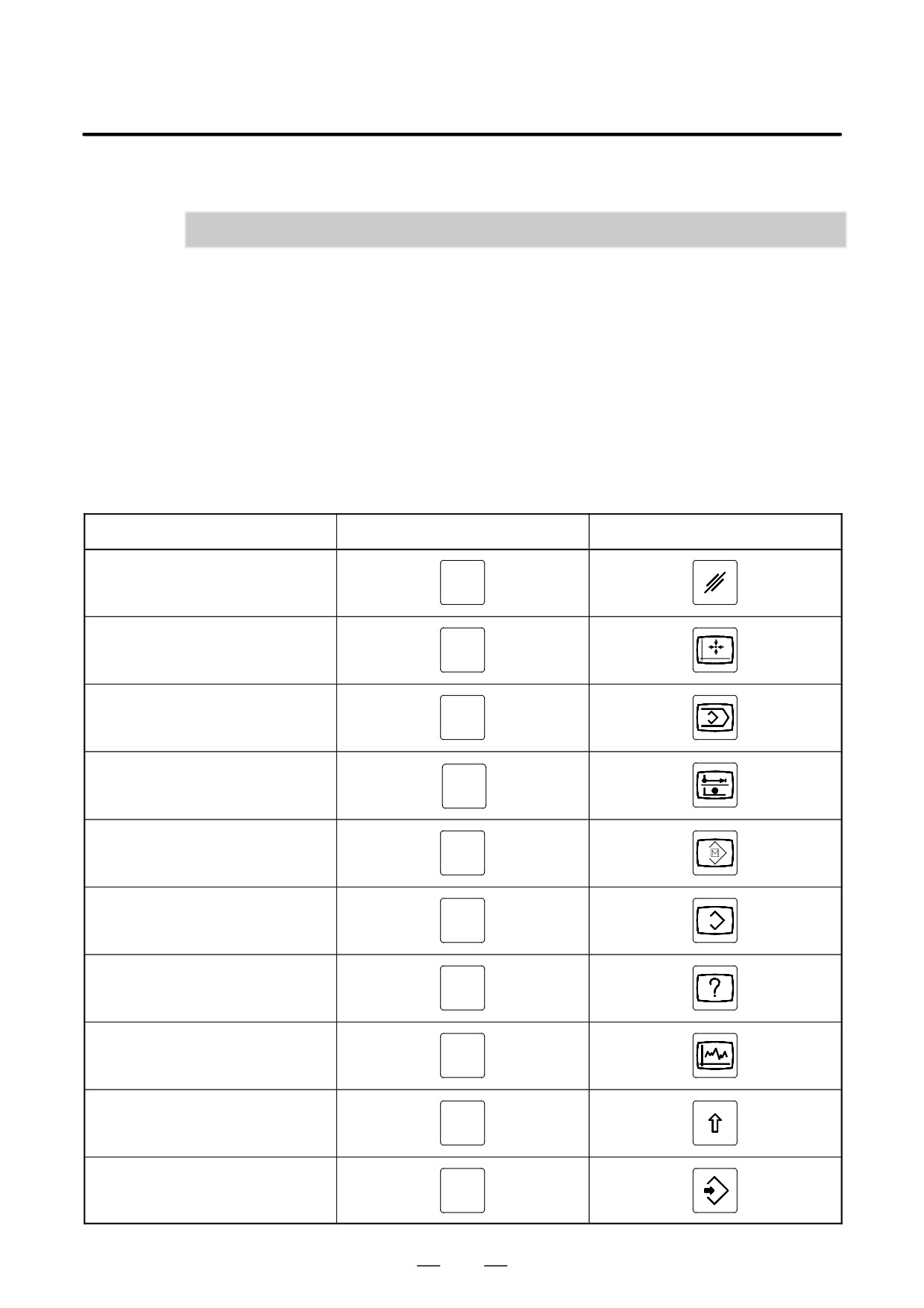
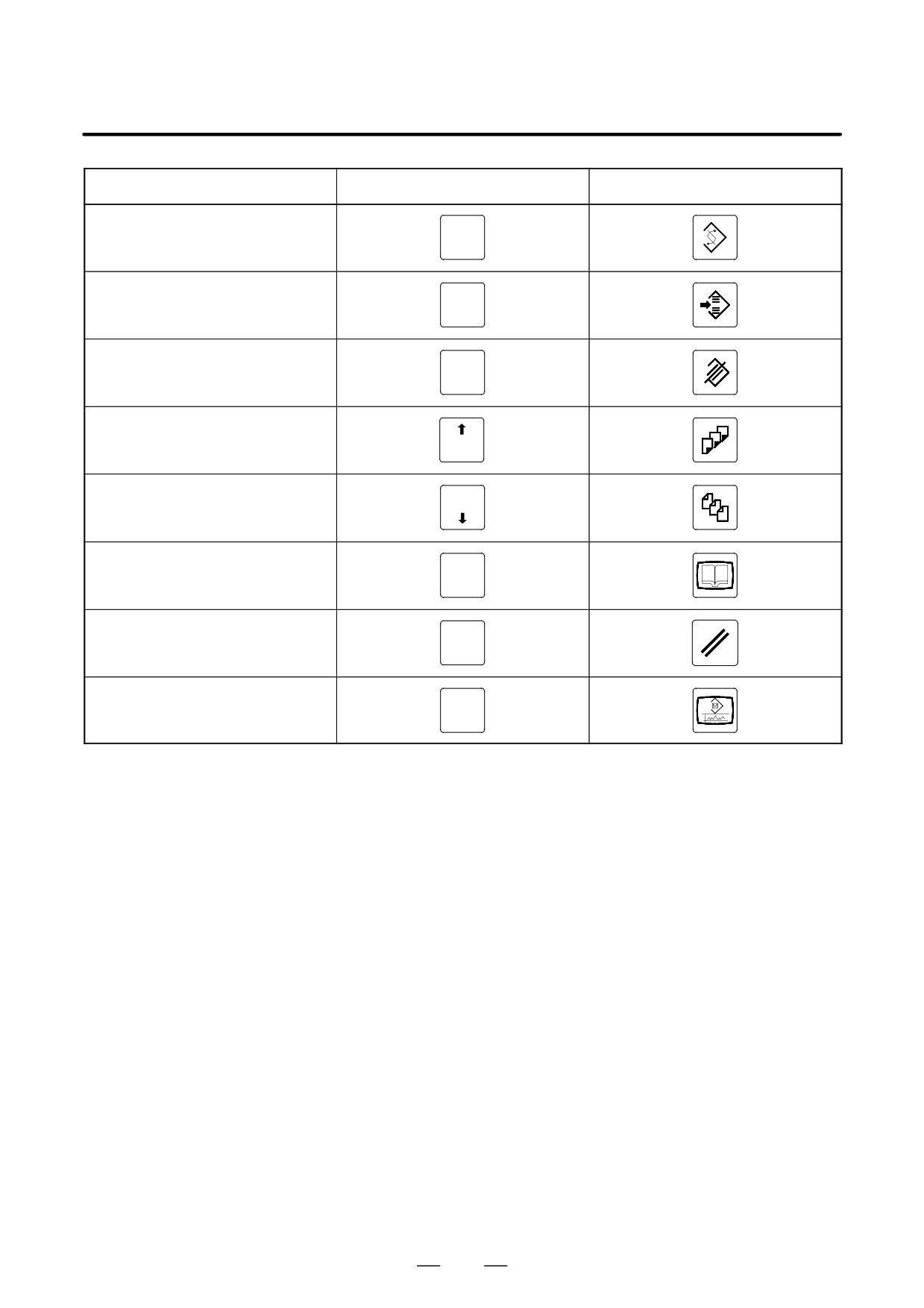
E
i series CNC have two types of MDI keypads : English type and Symbolic type.
The table below shows correspondence between English keys and Symbolic keys.
This manual uses English type in the text.
Therefore when a user uses Symbolic type MDI keypads and encounters an English key in the text, please refer
to the correspondence table shown below.
Name
English key
Symbolic key
CANCEL key
CAN
POSITION key
POS
PROGRAM key
PROG
OFFSET/
OFFSET
SETTING key
SETTING
CUSTOM key
CUSTOM
SYSTEM key
SYSTEM
MESSAGE key
MESSAGE
GRAPH key
GRAPH
SHIFT key
SHIFT
INPUT key
INPUT
658
B-64115EN/02
APPENDIX
E. NOTATION OF MDI KEYS
Name
English key
Symbolic key
ALTER key
ALTER
INSERT key
INSERT
DELETE key
DELETE
PAGE UP key
PAGE
PAGE
PAGE DOWN key
HELP key
HELP
RESET key
RESET
CUSTOM
CUSTOM/GRAPH key
GRAPH
659