FANUC Series 0i-MODEL C, Series 0i Mate-MODEL C. MAINTENANCE MANUAL - page 12
4. INTERFACE BETWEEN CNC AND PMC
B-64115EN/02
ii)
PMC system parameter
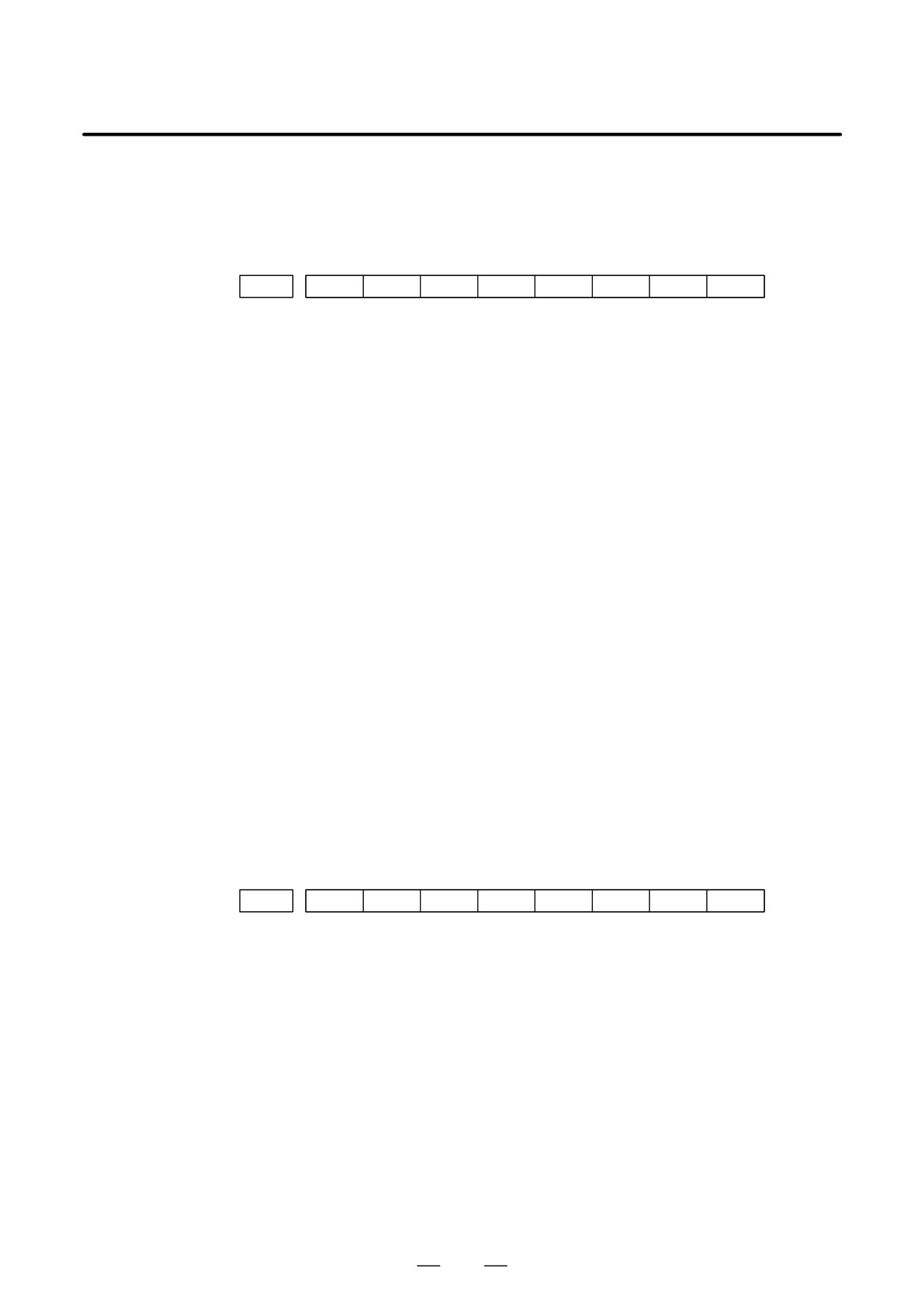
Since the system uses keep relays K17 to K19, they cannot be used by
a sequence program.
#7
#6
#5
#4
#3
#2
#1
#0
K17
DTBLDSP
ANASTAT
TRCSTAT
MEMINP
AUTORUN
PRGRAM
LADMASK
#0 (LADMASK):
0:
The ladder programs are displayed dynamically (PCLAD).
1:
The ladder programs are not displayed dynamically (PCLAD).
#1 (PRGRAM):
0:
The built-in programmer function does not operate.
(Also, the
programmer menu is not displayed.)
1:
The built-in programmer function operates. (The programmer menu
is displayed.)
#2 (AUTORUN):
0:
The sequence program automatically starts at power on.
1:
Pressing the soft key to sequence program execution starts the
sequence program.
#4 (MEMINP):
0:
The forcing function is disabled.
1:
The forcing function is enabled.
#5 (TRCSTAT):
0:
Pressing the [EXEC] soft key starts tracing by the signal trace
function.
1:
The signal trace function automatically starts tracing at power on.
#6 (ANASTAT):
0:
Pressing the soft key to execution starts sampling by the signal
waveform display function.
1:
The signal waveform display function automatically starts sampling
at power on.
: This bit is only effective for those models for which the signal
waveform display function is applicable.
#7 (DTBLDSP):
0:
The PMC parameter data table control screen is displayed.
1:
The PMC parameter data table control screen is not displayed.
#7
#6
#5
#4
#3
#2
#1
#0
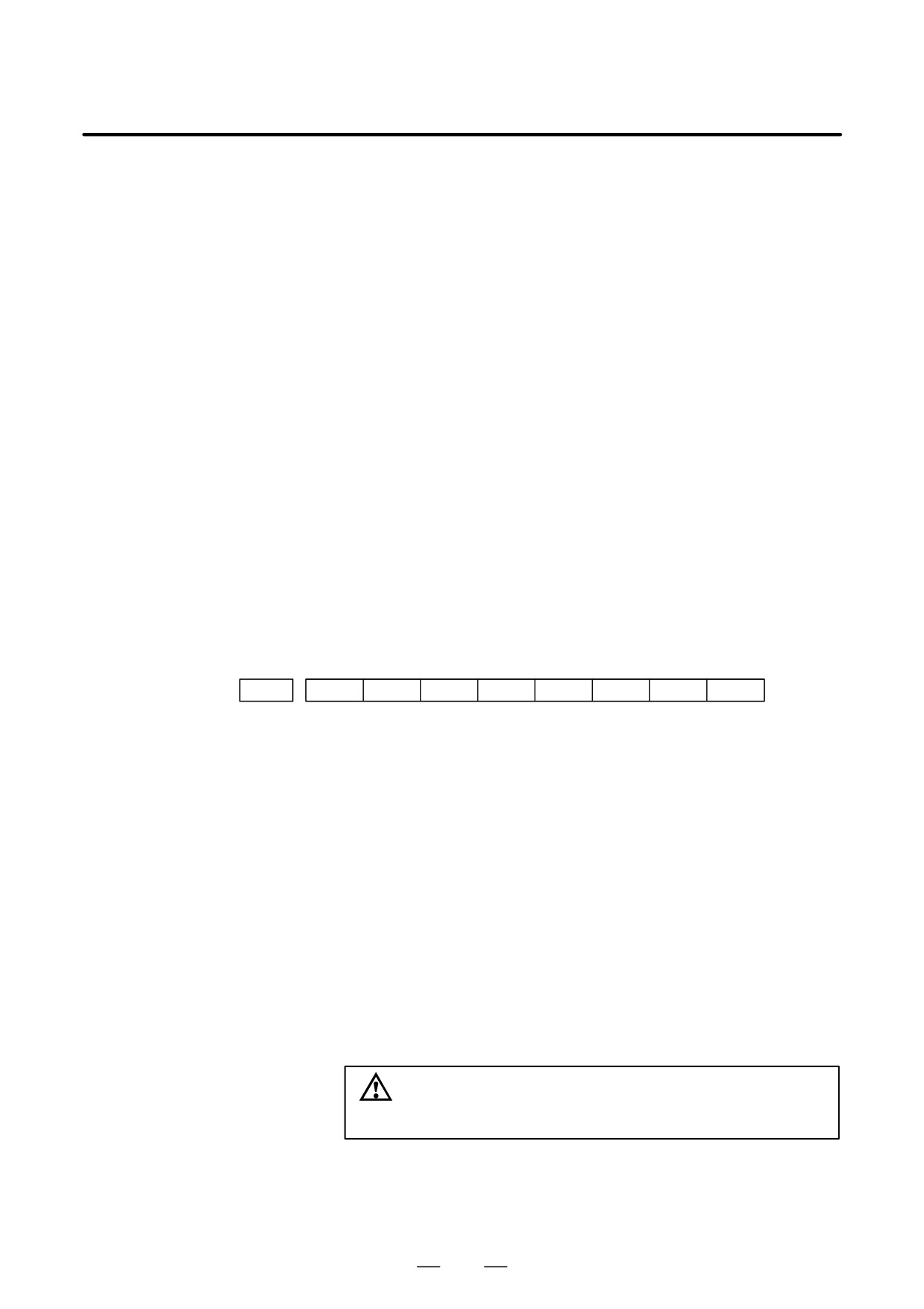
K018
IGNDINT
EDITLAD
CHKPRTY
CALCPRTY
TRNSRAM
TRGSTAT
DBGSTAT
IGNKEY
#0 (IGNKEY):
0: Function keys are enabled for a user program on the user screen.
1: Function keys are disabled for a user program on the user screen.
: This flag is useful when a user program is used. When this bit is set
to 1, the user screen cannot be switched to the NC screen by using the
function keys. A program which invariably sets this bit to 0, or which
switches the user screen to the NC screen, must be prepared.
#1 (DBGSTAT):
0: The C language debug function does not start automatic break
processing at power on.
1: The C language debug function starts automatic break processing at
power on.
: This flag is useful when a user program is used.
#2 (TRGSTAT):
0: The trigger stop function does not automatically start at power on.
1: The trigger stop function starts automatically at power on.
310
B-64115EN/02
4. INTERFACE BETWEEN CNC AND PMC
#3 (TRNSRAM):
0:
After on-line editing, the ladder program is not automatically
transferred to the backup RAM.
1:
After on-line editing, the ladder program is automatically transferred
to the backup RAM.
#4 (CALCPRTY):
0:
The built-in programmer function calculates the RAM parity.
1:
The built-in programmer function does not calculate the RAM parity.
#5 (CHKPRTY):
0:
The system performs parity check for the system ROM, program
ROM and program RAM.
1:
The system does not perform parity check for the system ROM,
program ROM, or program RAM.
#6 (EDITLAD):
0:
The editing of a sequence program is disabled.
1:
The editing of a sequence program is enabled.
#7 (IGNDINT):
0:
The system initializes the LCD when the screen is switched to the
PMCMDI screen.
1:
The system does not initialize the LCD when the screen is switched to
the PMCMDI screen.
: This flag is useful when a user program is used. When the screen is
switched to the PMCMDI screen, PMC control software determines
whether the system initialize the LCD, by checking this flag. When
this flag is on, an application program must initialize the LCD.
#7
#6
#5
#4
#3
#2
#1
#0
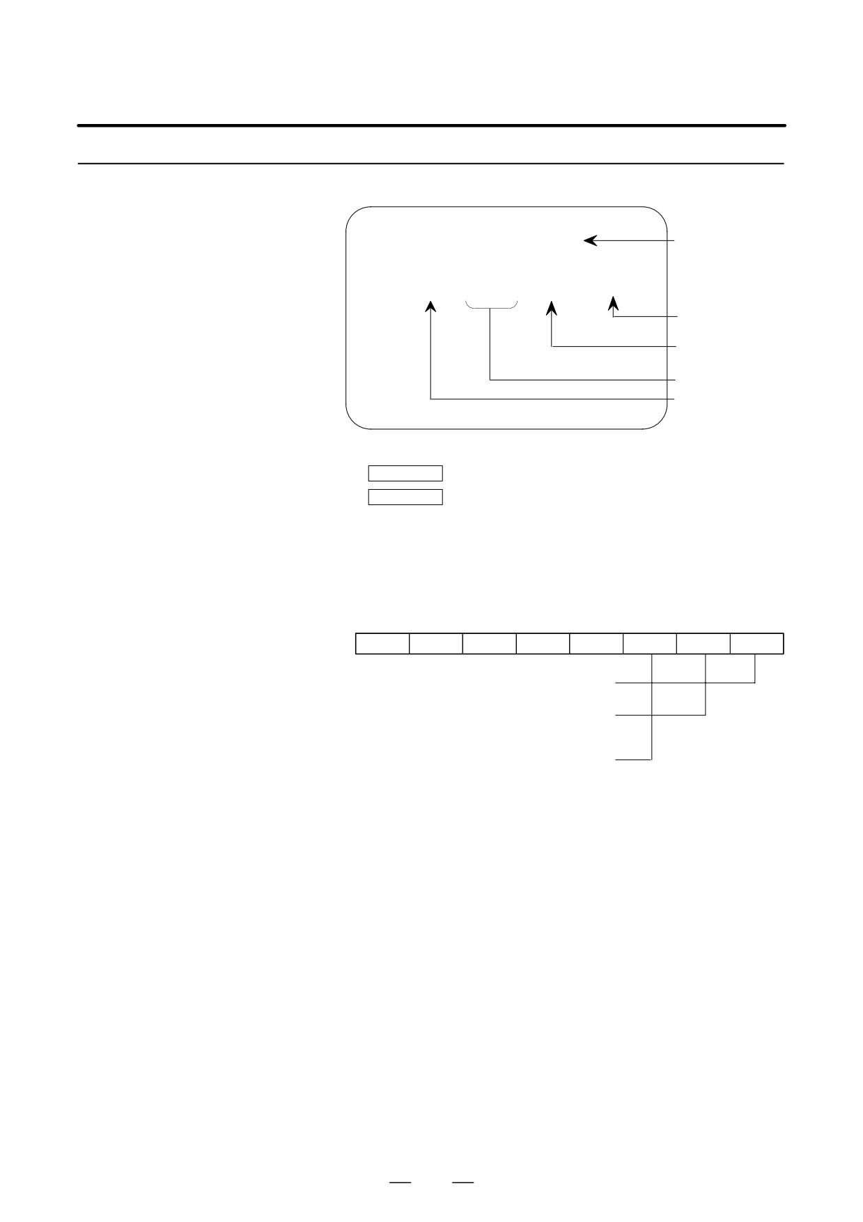
K019
PTCTPRM
HIDEPRM
ALWSTP
C-REJECT
FROM-WRT
#0 (FROM_WRT):
0: After editing a ladder or C program, does not automatically write it to
F-ROM.
1: After editing a ladder or C program, automatically writes it to
F-ROM.
#1 (C-REJECT):
0: The system activates a C program.
1: The system does not activate a C program.
#2 (ALWSTP):
0: The execution/stop operation of a sequence program is disabled.
1: The execution/stop operation of a sequence program is enabled.
#6 (HIDEPRM):
0: The display of PMC parameters and the output of PMC parameters to
the outside are enabled.
1: The display of PMC parameters and the output of PMC parameters to
the outside are disabled.
#7 (PTCTPRM):
0: The modification and reading of PMC parameters are enabled.
1: The modification and reading of PMC parameters are disabled.
CAUTION
Set all unused bits to 0.
311
4. INTERFACE BETWEEN CNC AND PMC
B-64115EN/02
4.3.4.5
1)
DATA TABLE SETTING screen (C. DATA)
Data table screen
PMC DATA TBL CONTROL #001
MONIT RUN
Number of
(C. DATA)
GROUP TABLE COUNT = 2
data table
group
NO. ADDRESS PARAMETER TYPE NO.OF DATA
001
D0000
00000000
0
10
Number of
002
D0020
00000011
1
20
data of
each data
003
table
004
Data length
005
006
Table
007
parameter
008
Head
address of
[ G.DATA ]
[
G.CONT
]
[
NO.SRH
]
[
]
[
INIT
]
data table
(a) [G.DATA] soft key : Select the data display screen of data table.
(b)
No. of group
[G.CONT] : Set the number of group for data table.
(c)
No. of group
[NO.SRH] : Move the cursor to specified group.
(d) [INIT] soft key : Initialize of data table setting.
No. of group is
1, ADDRESS is D0000,
PARAMETER is 00000000, TYPE is 0, NO. OF
DATA is 1860.
ƠTable parameterơ
#7
#6
#5
#4
#0
#3ÇÇ#2ÇÇÇÇ#1
ÇÇÇÇÇÇÇÇÇ
0 : Binary format
1 : BCD format
Protection of input data,
0 : not provided.
1 : provided.
0 : Displayed in binary or BCD (bit 0 is enabled)
1 : Displayed in hexadecimal (bit 0 is disabled)
ƠTYPEơ
0 : 1byte
1 : 2bytes
2 : 4bytes
312

B-64115EN/02
4. INTERFACE BETWEEN CNC AND PMC
2) Data setting screen (G. DATA)
Group number
Number of page
PMC PRM (DATA) 001/001
MONIT RUN
NO. ADDRESS DATA
000
D0000
0
001
D0001
0
002
D0002
0
003
D0003
0
004
D0004
0
005
D0005
0
006
D0006
0
007
D0007
0
008
D0008
0
009
D0009
0
[ C.DATA ]
[
G-SRCH
]
[
SEARCH
]
[
]
[
]
(a) [C.DATA] soft key : Return to data table setting screen.
(b)
Group No.
[G-SRCH] : Move the cursor to head of specified group.
(c)
Address
[SEARCH] : Searching the specified address in
currentup group.
313
4. INTERFACE BETWEEN CNC AND PMC
B-64115EN/02
4.3.4.6
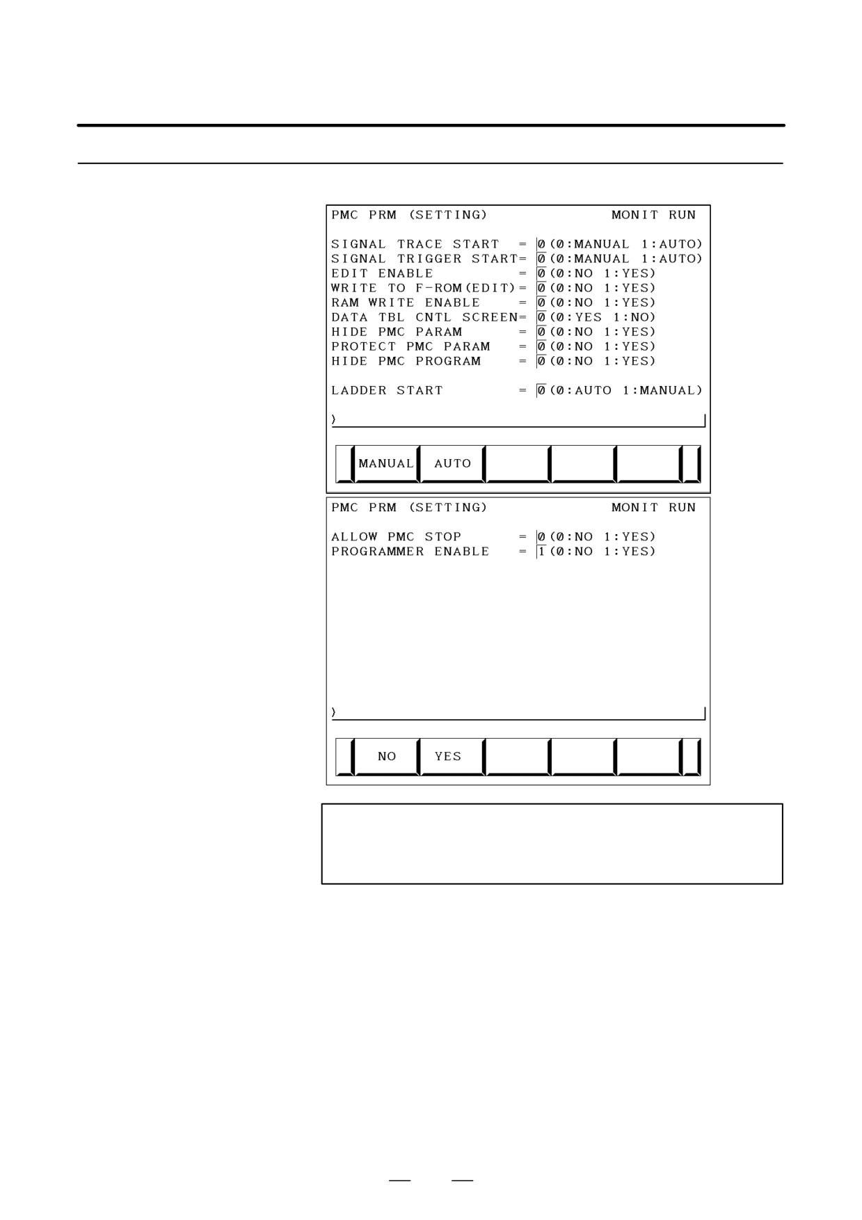
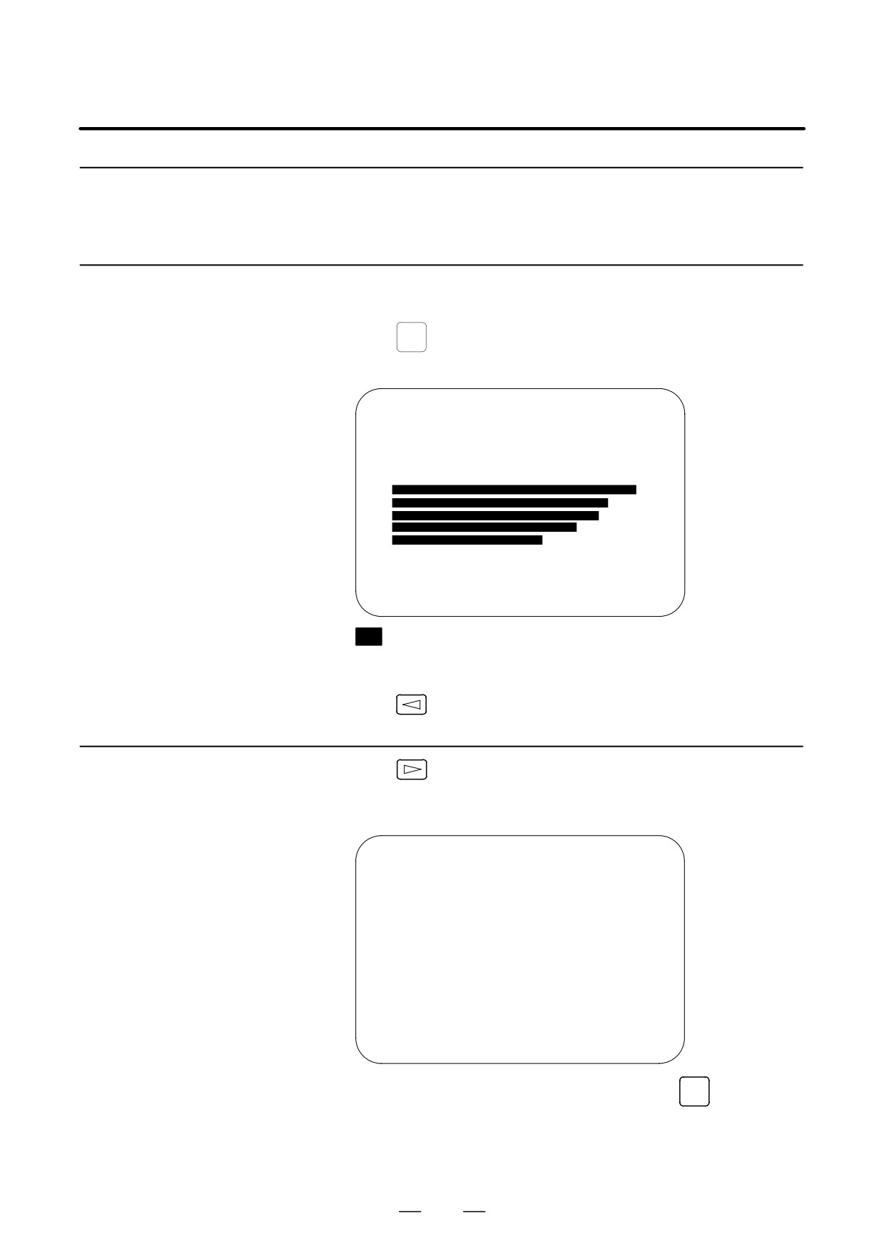
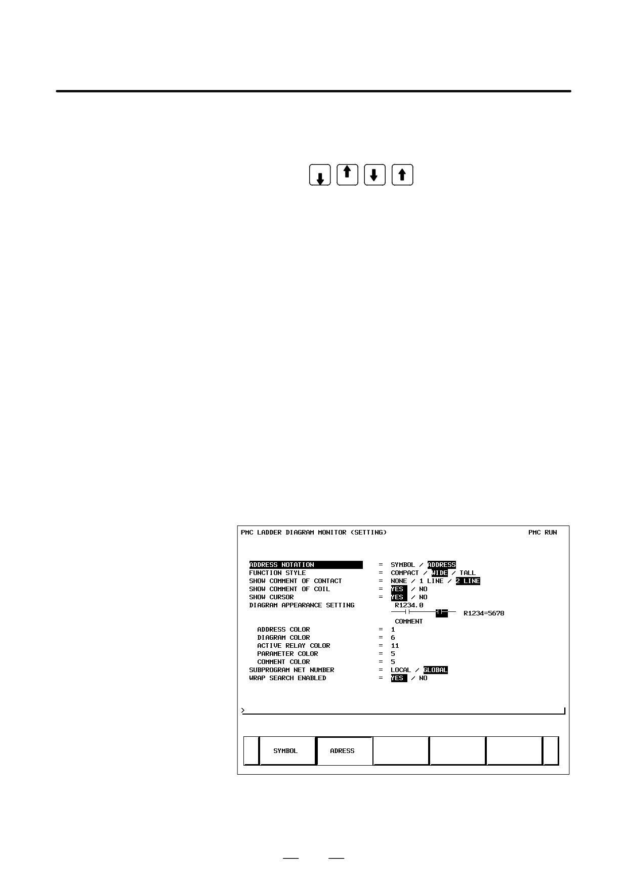
Some PMC system parameters can be set on this screen.
Setting screen
(K17.5)
(K18.2)
(K18.6)
(K19.0)
(K17.4)
(K17.7)
(K19.6)
(K19.7)
(K17.0)
(K17.2)
(K19.2)
(K17.1)
NOTE
The parenthesized values to the right of the screen indicate
keep relay addresses.
314
B-64115EN/02
4. INTERFACE BETWEEN CNC AND PMC
4.3.5
Input/Output of PMC
Data
:
As following operation is not required when the data set from MDI.
4.3.5.1
1
Select the PMC screen
Start of the built-in type
PMC programmer
SYSTEM
Press
key and press [PMC] soft key.
2
Confirm to the built-in type PMC programmer is running.
PMC CONTROL SYSTEM MENU
MONIT RUN
SELECT ONE OF FOLLOWING SOFT KEYS
PMCLAD
: DYNAMIC LADDER DISPLAY
PMCDGN
: DIAGNOSIS FUNCTION
PMCPRM
: PARAMETER (T/C/K/D)
RUN/STOP
: RUN/STOP SEQUENCE PROGRAM
EDIT
: EDIT SEQUENCE PROGRAM
I/O
: I/O SEQUENCE PROGRAM
SYSPRM
: SYSTEM PARAMETER
MONIT
: PMC MONITOR
[ PMCLAD]
[
PMCDGN
]
[
PMCPRM
]
[
]
[
]
parts are displayed, starts of the built-in type PMC programmer.
3
Keep relay K17.1 should set to
“1” if the built-in type PMC
programmer is not start yet.
4
Press
key to return to initial menu screen.
4.3.5.2
1
Press
key in the initial menu screen, then display to [I/O] soft
Input/output method
key.
2
Display next screen
PMC I/O PROGRAM
MONIT RUN
CHANNEL
=
1
DEVICE
= HOST
FUNCTION
=
DATA KIND
=
[ EXEC ]
[CANCEL]
[
(NO.)
]
[
]
[
]
3
Enter the desired channel number, then press the
INPUT
key to set the
number for CHANNEL.
1 : JD5A of the main CPU board
2 : JD5B of the main CPU board
315

4. INTERFACE BETWEEN CNC AND PMC
B-64115EN/02
4
Specify the I/O unit to be used for DEVICE.
HOST:
I/O operation with FAPT LADDER (on the P-G, P-G
Mate, or personal computer)
FDCAS: I/O operation with a Floppy Cassette Adaptor
F-ROM: I/O operation with a flash EEPROM
M-CARD: I/O operation with a memory card
OTHERS: I/O operation with other I/O units
5
Specify the desired function with FUNCTION.
WRITE: Outputting data
READ:
Inputting data
COMPARE: Comparing data in memory with that in an external
device
DELETE: Deleting files on a floppy disk or memory card
LIST:
Listing the files on a floppy disk or memory card
BLANK:
Checking whether the flash EEPROM is empty
ERASE:
Clearing the data in the flash EEPROM
FORMAT: Formatting a memory card (all data on the memory card
is deleted.)
6
Specify the desired type of data to be output at KIND DATA.
LADDER: Ladder programs
PARAM: PMC parameters
7
When FDCAS or M-CARD is specified for the device, a file can be
specified for FILE NO. by either its file number or file name.
8
Specify the RS-232C conditions for each device with SPEED.
9
Check that the settings are correct. Then, press the [EXEC] soft key.
4.3.5.3
Changes made during on-line editing are transferred to the corresponding
editing ladder program.
Copy function (COPY)
316
B-64115EN/02
4. INTERFACE BETWEEN CNC AND PMC
4.3.6
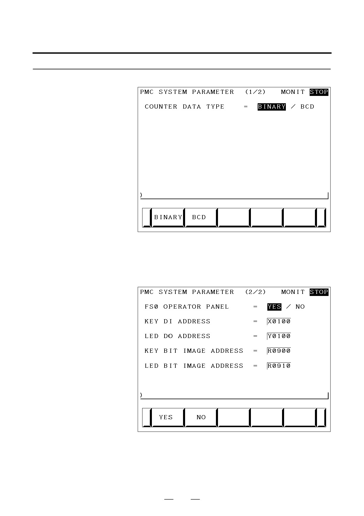
(1) System parameter screen (1/2)
System Parameters
Display information
• COUNTER DATA TYPE :
Specify the binary format or BCD format for a counter value to
be used with the function instruction CTR.
(2) System parameter screen (2/2)
Display information
• FS0 OPERATOR PANEL :
Set whether to connect an operator’s panel for the FS0.
• KEY DI ADDRESS :
Set the start address of an external DI actually connected.
317
4. INTERFACE BETWEEN CNC AND PMC
B-64115EN/02
• LED DO ADDRESS :
Set the start address of an external DO actually connected.
• KEY BIT IMAGE ADDRESS :
Set the start address of a key image referenced by a user
program. Usually, set an arbitrary internal relay (R) area.
• LED BIT IMAGE ADDRESS :
Set the start address of an LED image generated by a user
program. Usually, set an arbitrary internal relay (R) area.
4.3.7
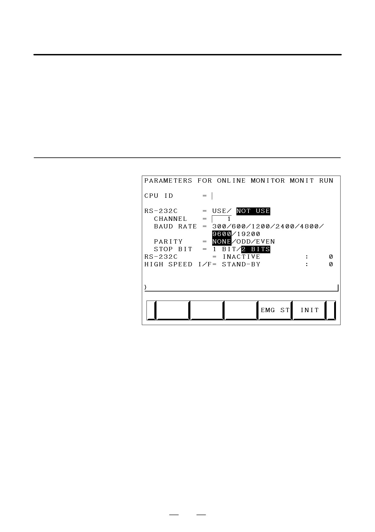
Online Monitor Setting
Screen
(a) Soft key
•
[EMG ST] : Terminates communication forcibly. Use this key if
communication becomes abnormal and the
connection cannot be terminated normally.
•
[INIT]
: Initializes the parameters to their default values.
(b) Setting
• CPU ID
: Displays a CPU ID value. However, do not
modify this item.
• RS-232C
: Enables communication setting in the case of
connection via RS-232C. However, do not
modify the items of TIMER 1, TIMER 2,
TIMER 3, and MAX PACKET SIZE.
• HIGH SPEED I/F : Enables setting for connection via a
high-speed interface (HSSB, Ethernet).
318

B-64115EN/02
4. INTERFACE BETWEEN CNC AND PMC
NOTE
1
When both ”RS-232C = USE” and ”HIGH SPEED I/F =
USE” are selected, the PMC system will communicate with
the application which is connected at first. If PMC system is
already connecting with an application, it can not connect
with other applications.
2
When you use the online function by Ethernet, the setting
of Ethernet parameters at CNC is necessary in advance.
(c) Communication status
• USE TIME
: The maximum time in the communication
processing is displayed.
• RS-232C
: The communication condition of RS-232C is
displayed.
• HIGH SPEED I/F : The communication condition of HIGH
SPEED I/F is displayed.
• ETHER_BOARD : Displayed during the communication with
Ethernet board. The IP address of the
communication partner is displayed.
• EMB_ETHERNET: Displayed during the communication with
embedded Ethernet. The IP address of the
communication partner is displayed.
• HSSB
: Displayed during the communication with
HSSB.
319

4. INTERFACE BETWEEN CNC AND PMC
B-64115EN/02
Display messages and the meanings
Display
Meanings
messages
INACTIVE
The communication is inactive.
STOPPING
The communication is being stopped.
(Wait for the termination of communication)
STARTING
The communication is being started.
(Wait for the termination of communication over anoth-
er communication path)
STAND-BY
The communication is active and in standby mode.
CONNECTED
The communication is active and being connected.
NO OPTION
The port can be not opened because there is not op-
tion of RS-232C.
BAD PARAMETER
Invalid open parameters are specified.
TIMEOUT ERROR
A time-out has occurred and communication is
aborted.
TIMEOUT(K)
A time-out has occurred and communication is
ERROR
aborted.
BCC ERROR
A Block Check Code (packet parity) error has occurred.
PARITY ERROR
A parity error has occurred.
OVER-RUN
A reception overrun has occurred and the communica-
ERROR
tion can not recover.
SEQUENCE
Packets are out of sequence. (Incorrect procedure)
ERROR
DATA ERROR
Incorrect packets have been received through retry
process.
QUEUE
The transmit/receive queue has overflowed.
OVERFLOW
DISCONNECTED
Communication has been terminated successfully.
NO CONNECTION
The cable is disconnected.
320

B-64115EN/02
4. INTERFACE BETWEEN CNC AND PMC
4.4
PMC SCREEN
(PMC-SB7)
4.4.1
PMC Menu Selection
Procedure Using Soft
Keys
PMC-SB7 screen menu selection procedure
[PMC]
[PMCLAD]
[EDIT]
Ladder diagram display screen
Selection monitor function
Ladder diagram editing screen
[PMCDGN]
[TITLE]
Title screen
[STATUS]
Signal status screen
[ALARM]
Alarm screen
[TRACE]
Signal trace screen
[IOCHK]
I/O check screen
[PMCPRM]
[TIMER]
Timer screen
[COUNTR]
Counter screen
[KEEPRL]
Keep relay screen
[DATA]
[G.DATA]
Data table screen
[SETING]
Setting screen
[RUN]/[STOP]
Ladder start/stop
[EDIT]
[TITLE]
Title editing screen
[SYMBOL]
Symbol/comment editing screen
[MESAGE]
Message editing screen
[MODULE]
I/O unit address setting screen
[CROSS]
Cross reference screen
[CLEAR]
Clear screen
[I/O]
Program/parameterinput/output screen
[SYSPRM]
System parameter screen
[MONIT]
[ONLINE]
Online setting screen
321
4. INTERFACE BETWEEN CNC AND PMC
B-64115EN/02
4.4.2
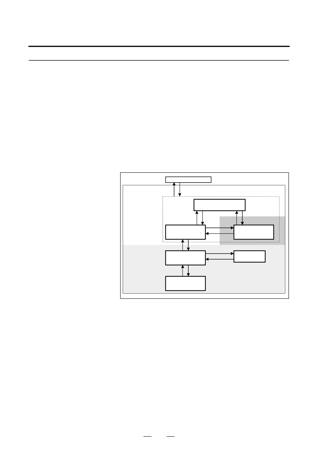
(1) Display method
Dynamic Display of
<1> Press the system key, then press the [PMC] soft key.
Sequence Programs
<2> Press the [PMCLAD] soft key to enable dynamic display of
sequence programs.
(2) Display information
The ladder diagram display/editing function consists of the following
screens:
a) Ladder diagram display screen
b) Selection monitor screen
c) Ladder diagram editing screen
d) Net editing screen
e) Program list display screen
f) Program list editing screen
PMC main menu
[<]
[PMCLAD]
Display
Program list
Display function
display screen
(monitor)
[LIST]
[ZOOM]
[LIST]
[ZOOM]
[SWITCH]
Ladder diagram
Selectionmonitor
display screen
screen
[SWITCH]
[<]
[EDIT]
[LIST]
Program list
Ladder diagram
Editing function
editing screen
editing screen
[ZOOM], [<]
[<]
[MODIFY], [ADD]
Net editing screen
322
B-64115EN/02
4. INTERFACE BETWEEN CNC AND PMC
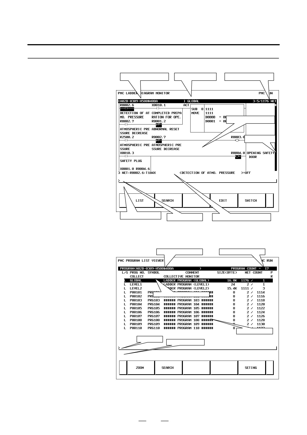
4.4.2.1
(1) Screen configuration
Ladder diagram display
Title information (remarks)
Display subprogram
Display position information
screen
Ladder diagram display area
Display position
Message display line
Key input line
Additional information display line
(2) Calling the program list display screen [LIST]
The program list display screen allows you to select a subprogram to
be displayed on the ladder diagram display screen.
Title information (details)
Total number of programs
Program subject to manipulation
List display area
Key input line
Message display line
323
4. INTERFACE BETWEEN CNC AND PMC
B-64115EN/02
(3) Searching for a signal [SEARCH]
<1> Press the [SEARCH] soft key.
<2> Search for a signal by using the keys indicated below.
D With PAGE
, the display area can be changed.
PAGE
D [TOPBTM] : The start/end of a ladder diagram is searched for.
D “Address” + [SEARCH] or “Signal name” + [SEARCH]:
A specified address or signal name is searched for.
D “net-number” + [SEARCH]:
A ladder is displayed from a specified net number.
D “Address” + [W-SRCH] or “Signal name” + [W-SRCH]:
The write coil is searched for a specified address or signal name.
D “function-instruction-number” + [F-SRCH] or
“function-instruction-name” + [F-SRCH]:
A specified function instruction is searched for.
D [PREV] : The previous search operation performed
successfully is repeated towards the start.
D [NEXT] : The previous search operation performed
successfully is repeated towards the end.
D [GLOBAL]/[LOCAL] : The search range is switched.
(4) Calling the function instruction data table display screen [TABLE]
The data table of a function instruction with a data table such as the
COD instruction (SUB7) and the CODB instruction (SUB27) can be
displayed.
(5) Setting the screen [SETING]
The setting screen for the ladder diagram display screen can be called.
Various settings for ladder diagram display can be modified.
324
B-64115EN/02
4. INTERFACE BETWEEN CNC AND PMC
4.4.2.2
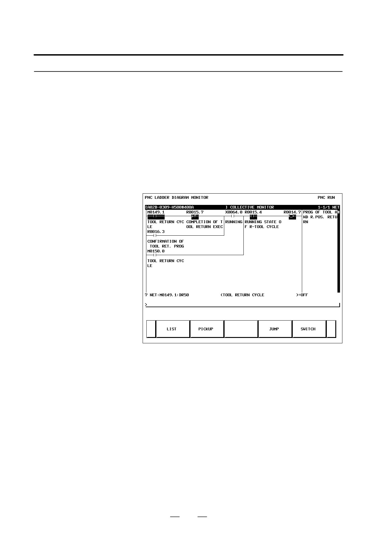
On the selection monitor screen, only a ladder net including a coil to be
monitored can be specified for ladder net monitoring.
Selection monitor screen
(1) Display method
(a) Calling the screen from the program list display screen
<1> Display the program list screen.
<2> Move the cursor to the “COLLECT”.
<3> Press the [ZOOM] soft key.
(b) Calling the screen from the ladder diagram display screen
<1> Display the ladder diagram display screen.
<2> Press the [SWITCH] soft key.
(2) Display information
(3) Specifying a ladder net to be monitored [PICKUP]
By using the method described below, a ladder net to be monitored on
the selection monitor screen can be read for display.
(a) Specifying a desired ladder net on the selection monitor screen
D Typing the address used with the coil to read the net
<1> Enter the address to be monitored.
<2> Press the [PICKUP] soft key.
<3> The net that uses the address specified by <1> with a coil
is read to the top of the screen.
D Specifying the ladder net on the selection monitor screen
<1> Move the cursor to the relay in the ladder net that uses an
address to be monitored.
<2> Press the [PICKUP] soft key.
<3> The net that uses the address specified by <1> with a coil
is read to the top of the screen, and the cursor moves to the
coil position.
325
4. INTERFACE BETWEEN CNC AND PMC
B-64115EN/02
(b) Specifying a desired ladder net on the ladder diagram display
screen
<1> Press the [SEARCH] soft key on the ladder diagram
display screen.
<2> Move the cursor to the ladder net to be read.
<3> Press the [PICKUP] soft key.
(4) Jumping to a ladder diagram on the ladder diagram display screen
[JUMP]
Make a jump by finding, on the ladder diagram display screen, the
ladder net where the cursor is placed on the selection monitor screen.
<1> Move the cursor to the net to which you want to jump.
<2> Press the [JUMP] soft key.
(5) Switching to the ladder diagram display screen [SWITCH]
The screen display can be switched to the ladder diagram display
screen.
(6) Deleting the display of one ladder diagram net [ERASE]
One ladder net read into the selection monitor screen can be erased
from the screen.
(7) Deleting the display of all ladder diagram nets [ERALL]
All ladder nets read into the selection monitor screen can be erased
from the screen.
On the ladder diagram editing screen, a ladder diagram can be edited to
4.4.2.3
change its operation.
Ladder diagram editing
(1) Display method
screen
<1> Display the ladder diagram monitor display screen by pressing
the [PMCLAD] soft key.
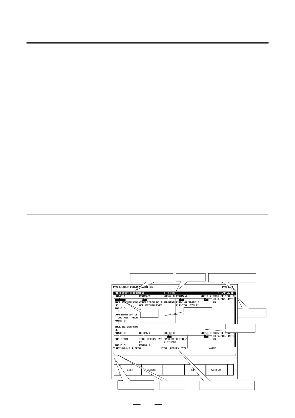
<2> Press the [EDIT] soft key.
(2) Display information
Title information (remarks)
Display program
Display position information
Editing target net
Display position
Cursor
gage
Ladder diagram
display position
Message display line
Key input line
Additional information display line
326

B-64115EN/02
4. INTERFACE BETWEEN CNC AND PMC
(3) Editing ladder programs
By using the keys below, a ladder diagram can be edited.
D
Selecting a subprogram to be edited
<1> Display the program list editing screen by pressing the [LIST]
soft key.
<2> Move the cursor to a subprogram to be edited.
D
Searching for a specified address or function instruction
<1> Press the [SEARCH] soft key.
<2> Switch to the soft key display for search.
For the search function, see “(3) Searching for a signal [SEARCH]”
in Subsection 4.4.2.1, “Ladder diagram display screen”.
D
Adding a new net
<1> Move the cursor to the position where a new net is to be added.
<2> Press the [CREATE] soft key to call the net editing screen.
Perform creation and addition operations to build a new net.
D
Modifying the structure of a selected net
<1> Move the cursor to a net to be modified.
<2> Call the net editing screen by pressing the [MODIFY] soft
key.
D
Changing the bit address of a relay
<1> Move the cursor to a relay to be modified.
<2> Enter a desired bit address then press the INPUT key. The bit
address of the relay where the cursor is placed is changed.
D
Modifying the parameter of a function instruction
<1> Move the cursor to the parameter of a function instruction to
be modified.
<2> Enter a desired number or byte address then press the INPUT
key. The parameter of the function instruction where the
cursor is placed is modified.
D
Reflecting modifications
<1> On the ladder diagram editing screen, modify a ladder
program.
<2> Press the
[UPDATE] soft key. The results of editing
performed so far are reflected in the ladder being executed.
When the modifications have been reflected normally, the
ladder after editing is executed.
D
Deleting a net
<1> Move the cursor to a net to be deleted.
<2> Press the [DELETE] soft key.
D
Moving a net
<1> Move the cursor to a net to be moved.
<2> By pressing the [CUT] soft key, cut the net.
<3> Move the cursor to the position to which the selected net is to
be moved.
<4> Press the [PASTE] soft key.
327
4. INTERFACE BETWEEN CNC AND PMC
B-64115EN/02
D
Copying a net
<1> Move the cursor to a net to be copied.
<2> Press the [COPY] soft key.
<3> Move the cursor to the position to which the selected net is to
be copied.
<4> Press the [PASTE] soft key.
D
Selecting multiple nets to be deleted/copied/moved
<1> Move the cursor to the start point of a desired net selection
range.
<2> Press the [SELECT] soft key.
<3> Move the cursor to the end point of the desired net selection
range.
<4> Press the [DELETE], [CUT], or [COPY] soft key to delete,
move, or copy the selected nets.
D
Discarding changes
Press the [RESTOR] soft key.
The results of editing performed so far are discarded to return to the
ladder present when you moved to the ladder diagram editing
screen or when you performed the last [UPDATE] processing.
D
Modifying the setting of the ladder diagram editing screen
Press the [SETING] soft key.
The setting screen of the ladder diagram editing screen is called.
D
Starting/stopping a ladder
Press the [RUN] or [STOP] soft key.
The execution of a ladder program is controlled. The [RUN] soft
key starts the execution of a ladder program, and the [STOP] soft
key stops the execution of a ladder program.
D
Ending the editing
Press the [<] key.
4.4.2.4
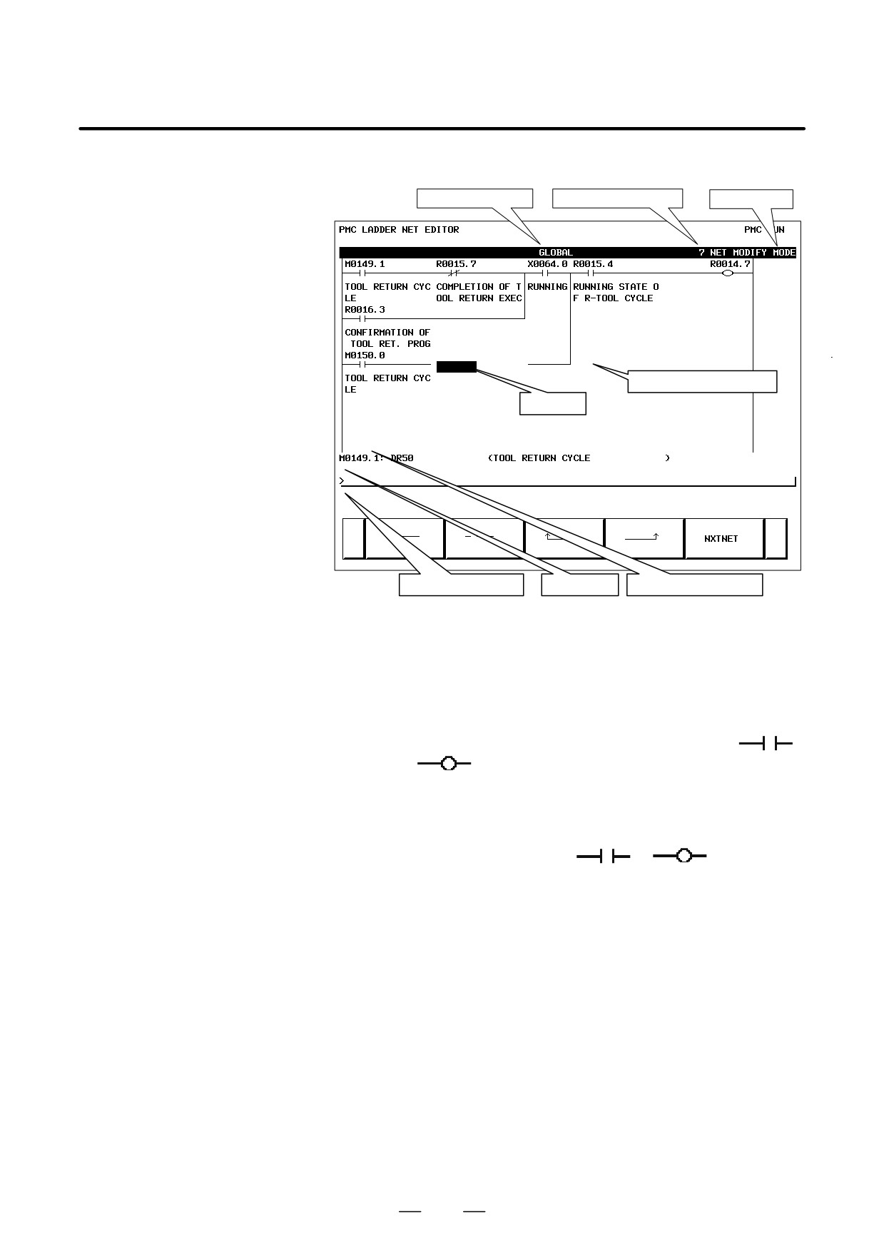
On the net editing screen, net editing operations such as the creation of
a new net and the modification of an existing net can be performed.
Net editing screen
D Modification to an existing net
If the net editing screen is displayed with the [MODIFY] soft key,
the mode (modification mode) for modifying the net indicated by
the cursor is set.
D Addition of a new net
If the net editing screen is displayed with the [CREATE] soft key,
the mode (creation mode) for creating a new net from a free state
is set.
(1) Display method
<1> Display the ladder diagram editing screen.
<2> Press the [CREATE] or [MODIFY] soft key.
328
B-64115EN/02
4. INTERFACE BETWEEN CNC AND PMC
(2) Display information
Display subprogram
Net number being edited
Editing mode
Ladder diagram display area
Cursor
Message
display line
Key input line
Additional information line
(3) Editing nets
By using the keys indicated below, a new net can be created, and an
existing net can be modified.
D Placing a new contact or coil
<1> Move the cursor to the position where a new contact or coil
is to be placed.
<2> Enter a bit address, then press a soft key such as [
],
[
].
D Changing the type of a contact or coil
<1> Move the cursor to the position where the type of a contact or
coil is to be changed.
<2> Press a soft key such as [
], [
].
D Changing the address of a contact or coil
<1> Move the cursor to a relay to be modified.
<2> Enter a bit address, then press the INPUT key.
D Placing a new function instruction
<1> Move the cursor to the position where a new function
instruction is to be placed.
<2> Enter a function instruction number, then press the [FUNC]
soft key.
D Changing the type of a function instruction
<1> Move the cursor to a function instruction to be modified.
<2> Enter a function instruction number.
329

4. INTERFACE BETWEEN CNC AND PMC
B-64115EN/02
D
Changing the parameter of a function instruction
<1> Move the cursor to the parameter of a function instruction to
be modified.
<2> Enter a number or byte address, then press the INPUT key.
D
Adding/deleting a connection line
<1> Move the cursor to the position where a connection line is to
be added or deleted.
<2> Press a soft key such as [
], [
], [
] for
addition.
<3> When deleting an existing connection line, press a soft key
such as [
], [
], [
].
D
Deleting a contact, coil, or function instruction
<1> Move the cursor to the position where a contact, coil, or
function instruction to be deleted is located.
<2> Press the [
] soft key.
D
Editing the next net
Press the [NXTNET] soft key. The editing operation of the net
currently being edited ends, and processing proceeds to the editing
of the next net.
D
Editing a function instruction data table
<1> Move the cursor to the function instruction that has a data
table to be edited.
<2> Press the [TABLE] soft key. The function instruction data
table editing screen appears.
<3> Move the cursor to the data table to be edited.
<4> Modify the selected data.
D
Inserting a line/column
<1> Move the cursor to the position where a line/column is to be
inserted.
<2> Press the [INSLIN], [INSCLM], or [APPCLM] soft key.
D
Discarding the results of editing
Press the [RESTOR] soft key.
330
B-64115EN/02
4. INTERFACE BETWEEN CNC AND PMC
4.4.3
Display method
Display of the PMC
<1> Press the system key, then press the [PMC] soft key.
Diagnosis Screen
<2> Press the [PMCDGN] soft key. The PMC diagnosis screen appears.
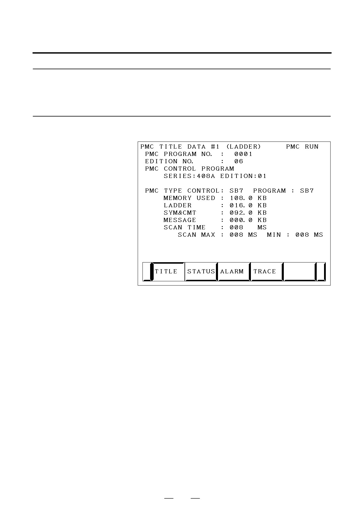
The title data registered at the time of ladder program creation is
4.4.3.1
displayed.
Title screen
Title data is the title of a sequence program, and consists of ten items:
D MACHINE TOOL BUILDER NAME (32 characters)
D MACHINE TOOL NAME (32 characters)
D CNC & PMC TYPE NAME (32 characters)
D PMC PROGRAM NO. (4 characters)
D EDITION NO. (2 characters)
D PROGRAM DRAWING NO. (32 characters)
D DATE OF PROGRAMMING (16 characters)
D PROGRAM DESIGNED BY (32 characters)
D ROM WRITTEN BY (32 characters)
D REMARKS (32 characters)
In addition, the following data is displayed:
D Series and edition of the PMC basic software
D Memory use status of each sequence data item
D Type of the PMC basic software and the PMC type of the sequence
program
D Current execution time, maximum execution time, and minimum
execution time of the ladder program
331
4. INTERFACE BETWEEN CNC AND PMC
B-64115EN/02
4.4.3.2
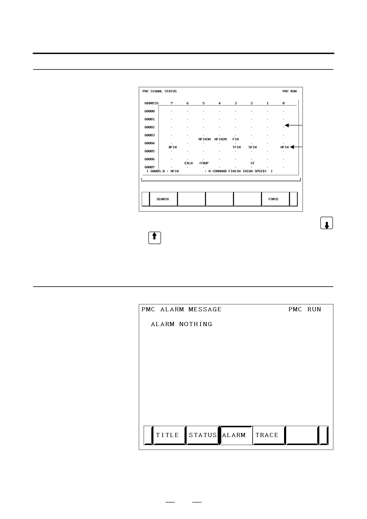
The on/off state of I/O signals and the internal relay is displayed.
Status screen
Signal state
.(period): Off
I: On
Signal name
PAGE
D The diagnosis number can be increased or decreased by using
PAGE
D Enter an address and number or signal name, then press the
[SEARCH] soft key. Then, the specified address or signal name is
searched for.
4.4.3.3
An alarm issued from the PMC is displayed.
Alarm screen
332
B-64115EN/02
4. INTERFACE BETWEEN CNC AND PMC
4.4.3.4
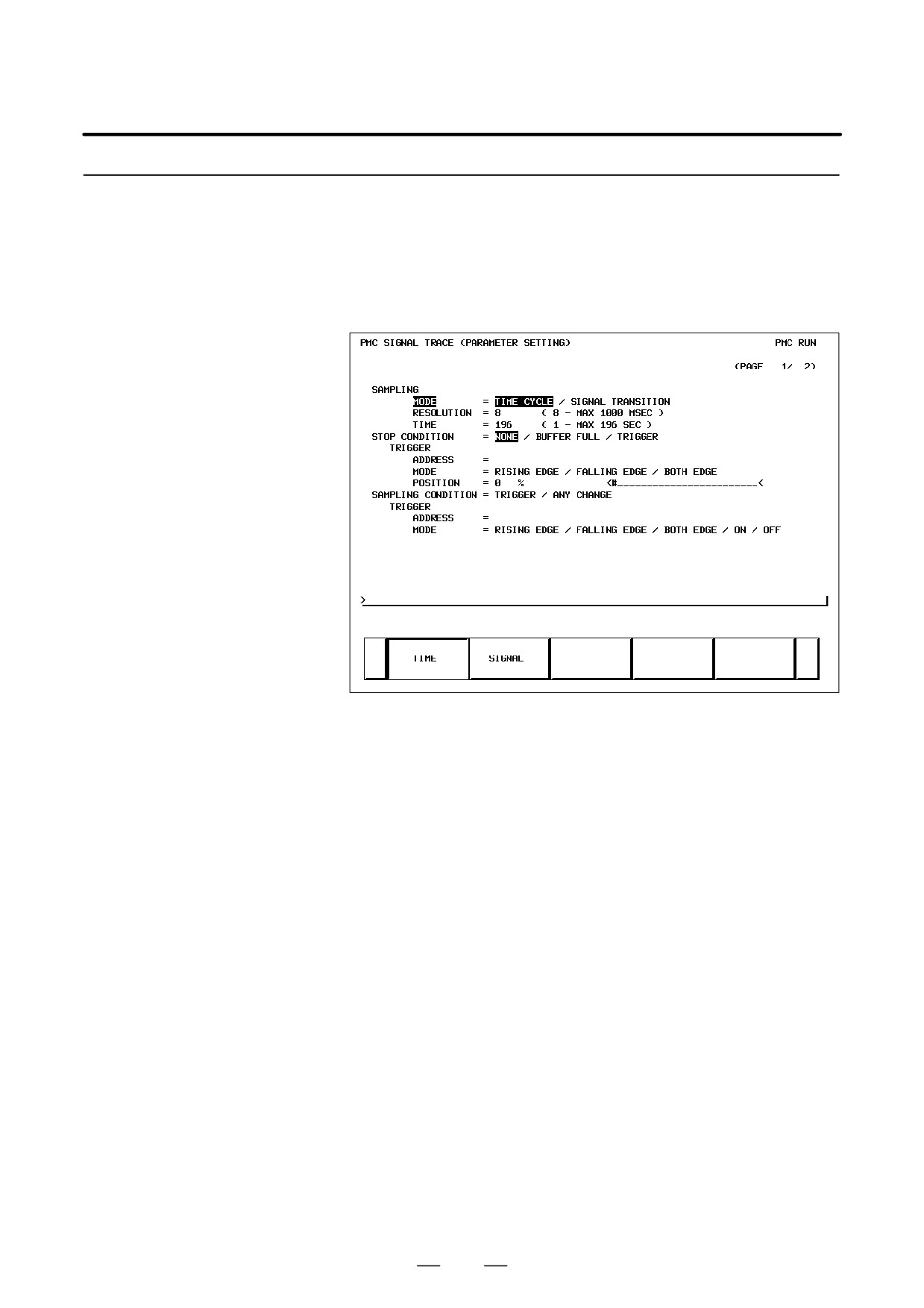
(1) Trace parameter screen (first page)
Trace function
<1> Press the system key, then press the [PMC] soft key.
<2> Press the [PMCDGN] soft key.
<3> Press the [TRACE] soft key.
<4> Press the [SETING] soft key on the signal trace screen.
a)
SAMPLING/MODE
Set a sampling mode.
D TIME CYCLE
:
Sampling based on a period of
time
D SIGNAL TRANSITION : Sampling based on signal
transitions
b)
SAMPLING/RESOLUTION
Set the resolution of sampling.
c)
SAMPLING/TIME
This item is displayed when “TIME CYCLE” is selected as the
sampling mode. Set a time interval for sampling.
d)
SAMPLING/FRAME
This item is displayed when “SIGNAL TRANSITION” is
selected as the sampling mode. Set the number of sampling
times.
e)
STOP CONDITION
Set a trace stop condition.
D NONE
:
Does not stop trace operation
automatically.
D BUFFER FULL : Stops trace operation automatically
when the sampling buffer becomes full.
D TRIGGER
:
Stops trace operation automatically by
a trigger.
333

4. INTERFACE BETWEEN CNC AND PMC
B-64115EN/02
f)
STOP CONDITION/TRIGGER/ADDRESS
This item becomes settable when “TRIGGER” is set as the trace
stop condition. Set a trigger address for stopping trace
operation.
g)
STOP CONDITION/TRIGGER/MODE
This item becomes settable when “TRIGGER” is set as the trace
stop condition. Set a trigger mode for stopping trace operation.
D RISING EDGE
:
Stops trace operation automatically
on the rising edge of the trigger signal.
D FALLING EDGE : Stops trace operation automatically
on the falling edge of the trigger signal.
D BOTH EDGE
:
Stops
trace
operation
automaticallyon a transition of the
trigger signal.
h)
STOP CONDITION/TRIGGER/POSITION
This item becomes settable when “TRIGGER” is set as the trace
stop condition. By using a ratio to the sampling time (or count),
set where to place a stop trigger occurrence position in the entire
sampling time (or count).
i)
SAMPLING CONDITION
This item becomes settable when “SIGNAL TRANSITION” is
set as the sampling mode. Set a sampling condition.
D TRIGGER
:
Performs sampling when the
sampling trigger condition is
satisfied.
D ANY CHANGE
:
Perform sampling when a sampling
address signal transition occurs.
j)
SAMPLING CONDITION/TRIGGER/ADDRESS
This item becomes settable when “SIGNAL TRANSITION” is
set as the sampling mode and “Trigger” is set as the sampling
condition. Set an address used to trigger sampling.
k)
SAMPLING CONDITION/TRIGGER/MODE
This item becomes settable when “SIGNAL TRANSITION” is
set as the sampling mode and “Trigger” is set as the sampling
condition. Set a trigger condition mode.
D RISING EDGE
:
Performs sampling on the rising edge
of the trigger signal.
D FALLING EDGE : Performs sampling on the falling
edge of the trigger signal.
D BOTH EDGE
:
Performs sampling on a signal
transition.
D ON
:
Performs sampling when the trigger
signal is on.
D OFF
:
Performs sampling when the trigger
signal is off.
334
B-64115EN/02
4. INTERFACE BETWEEN CNC AND PMC
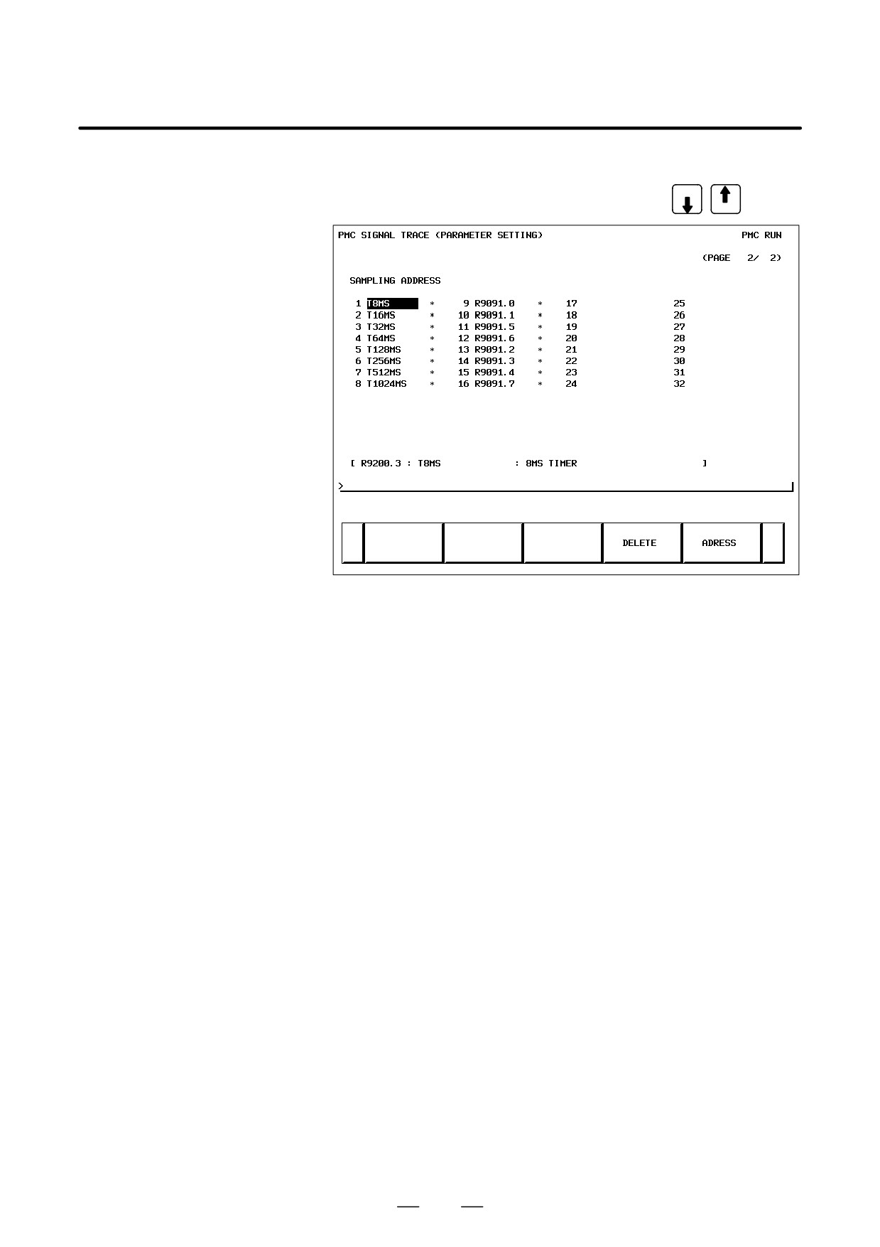
(2) Trace parameter screen (second page)
On the trace parameter screen (first page), press PAGE
PAGE
a)
Address setting
Set a signal address as a bit address. If you enter a byte address,
bits
0 to 7 of the entered address are input. Up to 32 signal
addresses can be set.
b)
Soft keys
D [DELETE]
: Deletes the set address where the
cursor is placed.
D [SYMBOL]/[ADRESS] : Switches the setting address
between symbol display and
address display.
D [MV.UP]
: Replaces the set address with the
upper line.
D [MV.DWN]
: Replaces the set address with the
lower line.
D [DELALL]
: Deletes all set addresses.
c)
Trigger setting
When “SIGNAL TRANSITION” is set as the trace sampling mode
and “BOTH EDGE” is set as the sampling condition, you can
choose whether to use a set address as a trigger signal for sampling.
To the right of a signal address set as a trigger, a “F” mark is
indicated.
D [TRGON]
: Turns on a trigger setting.
D [TRGOFF]
: Turns off a trigger setting.
335
4. INTERFACE BETWEEN CNC AND PMC
B-64115EN/02
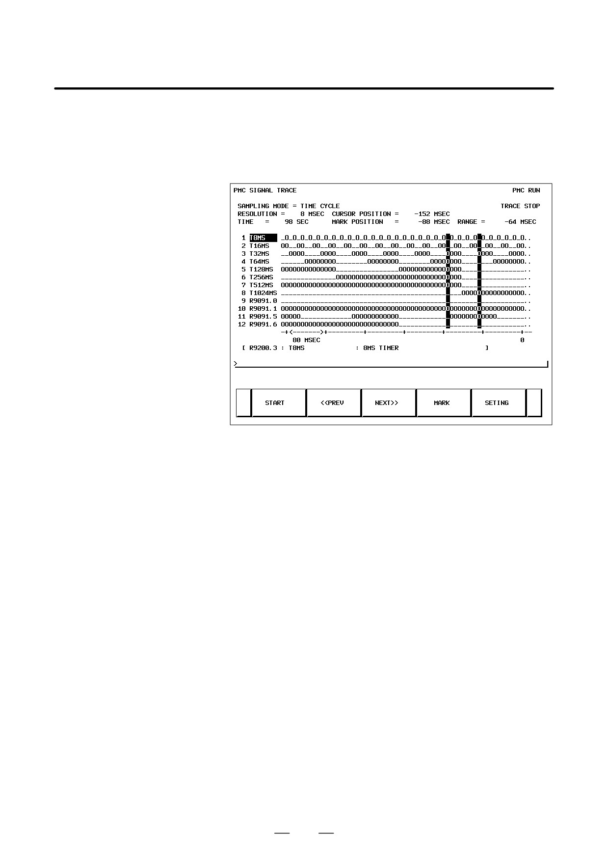
(3) Trace screen
<1> Press the system key, then press the [PMC] soft key.
<2> Press the [PMCDGN] soft key.
<3> Press the [TRACE] soft key.
(a) Executing trace operation
[START]
:
Executes trace operation.
(b) Stopping trace operation
[STOP]
:
Stops trace operation. Trace operation
ends also when the trace stop
condition set on the trace parameter
setting screen is satisfied.
(c) Checking trace results
Upon completion of trace execution, the results of trace
operation can be checked.
D Scrolling display
Cursor up/down key, page switch key:
Scrolls the set sampling signal
addresses up and down.
[<<PREV], [NEXT>>] Soft key, current right/left key:
Scrolls the graphical display of trace
results right and left.
D Performing automatic calculation and display of a selected
range
[MARK]
:
Marks the current cursor position, and
displays the mark cursor. To cancel
the range selection, press the [MARK]
soft key again.
D Enlarging/reducing display of trace results
[Z.IN]/[Z.OUT]
:
Enlarges/reduces graphical display.
336
B-64115EN/02
4. INTERFACE BETWEEN CNC AND PMC
D Replacing display data
[MV.UP]
:
Replaces the address where the cursor
is placed and the trace result of the
address with the upper line.
[MV.DWN]
:
Replaces the display data with the
lower line.
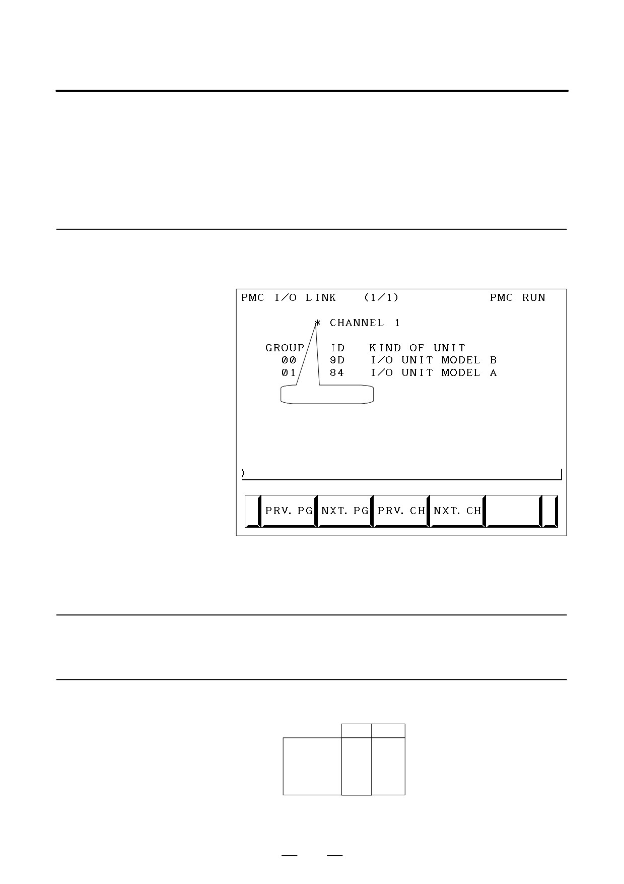
4.4.3.5
The type and ID code of an I/O device connected to the I/O Link are
displayed for each group. No data is displayed when no I/O device is
I/O Link connection
connected.
check screen
Channel enable mark
Channel enable mark : When a channel is usable, an “*” mark is
indicated. On the sample screen above, channel
2 is unusable.
4.4.4
PMC Parameters
4.4.4.1
<1> Place the NC in the MDI mode or in the emergency stop state.
Parameter input/output
<2> Set PWE of the NC setting screen to 1.
method
PWE
KEY4
Timer
f
Counter
f
f
either one
Keep relay
f
Data table
f
f
either one
<3> Alternatively, set the program protect signal (KEY4) to 1 only with
the counter and data table.
337
4. INTERFACE BETWEEN CNC AND PMC
B-64115EN/02
<4> Press a soft key and select a required screen.
[TIMER]
: Timer screen
[COUNTR] : Counter screen
[KEEPRL]
: Keep relay screen
[DATA]
: Data table screen
<5> Press cursor key and move the cursor to a desired number.
<6> Input a numeric key and press INPUT key and data is input.
<7> After input, return PWE or the KEY4 signal to the previous state.
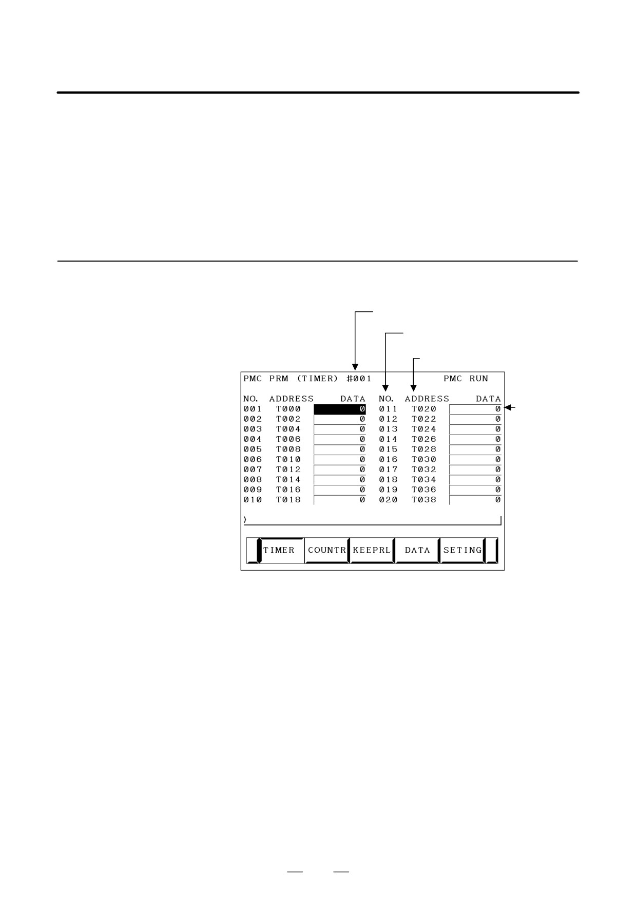
4.4.4.2
This screen is used for setting timer time of the Timer instruction (SUB
3).
TIMER screen
Page number (screen is scrolled by page key)
Timer number specified with the Timer instruction
Address referenced by the sequence program
Set a timer
period in ms.
Timer set time : Timer No. 1-8 is max. 1572.8 sec and its accuracy is
48ms. Timer No. 9 to 250 is max. 262.1 sec and its
accuracy is 8ms.
338
B-64115EN/02
4. INTERFACE BETWEEN CNC AND PMC
4.4.4.3
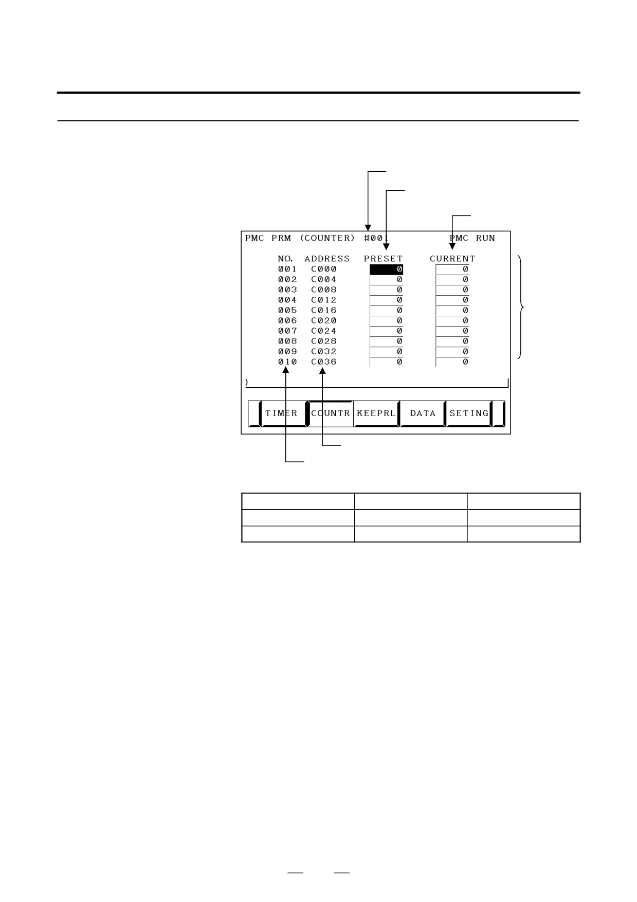
This screen sets and displays max. value of counter and current value of
the counter instruction (SUB 5).
COUNTER screen
Page No. (screen is scrolled by page key)
Max. value of counter (Minimum value is specified
by counter)
Current value of counter
Counter
numbers
from 1 to 100
Address referenced by the sequence program
Counter number specified by the counter instruction
Counter formats and maximum values
Counter format
Setting
Current value
BINARY
32767
32767
BCD
9999
9999
339