FANUC Series 30i-MODEL B, 31i-MODEL B, 32i-MODEL B. MAINTENANCE MANUAL - page 13
6.INTERFACE BETWEEN CNC AND PMC
B-64485EN/01
(3) R9002 to R9005, Z2 to Z5 (operation output registers for the DIVB functional instruction)
The remainder of a division performed with the DIVB functional instruction is output to these
addresses.
System timers
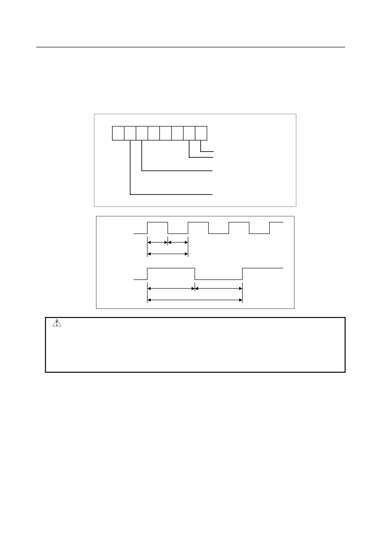
Four signals can be used as system timers.
Their specifications are as follows.
7
6
5
4
3
2
1
0
R9091
Z91
Constantly OFF signal
Constantly ON signal
200msec cyclic signal
(104msec ON and 96msec OFF)
1sec cyclic signal
(504msec ON and 496mec OFF)
R9091.5
Z91.5
104msec
96msec
200msec
R9091.6
Z91.6
504msec
496msec
1sec
CAUTION
1 Each signal is initially OFF.
2 The signals R9091.0, R9091.1, Z91.0, and Z91.1 are set at the beginning of the
first ladder level on every cycle.
3 Each pulse signal (ON-OFF signal) has an error of ±8 or 4 ms (ladder execution
period).
Ladder execution start signal
Ladder stop signal
Ladder execution status signal
Using the ladder execution start and stop signals in a ladder program can detect when the ladder program
starts and stops.
Referencing the ladder execution status signal from an external system or program, such as the network
board, C Language Executor program, FOCAS1 Ethernet, or HSSB library, can detect the execution
status of the ladder program.
- 342 -
B-64485EN/01
6.INTERFACE BETWEEN CNC AND PMC
7
6
5
4
3
2
1
0
R9015
Z15
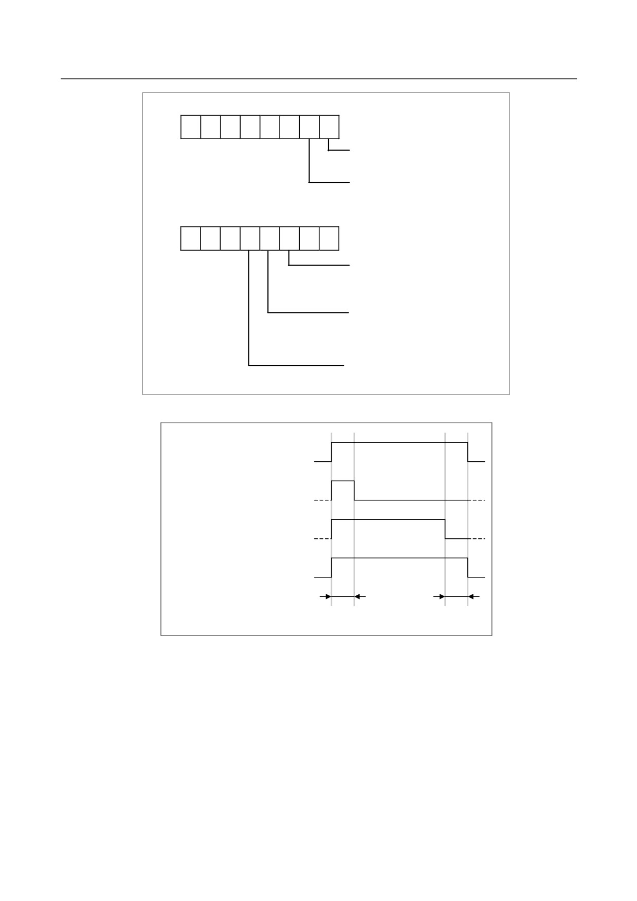
"Ladder execution start signal"
(can be referenced only from the
ladder program)
"Ladder stop signal"
(can be referenced only from the
ladder program)
7
6
5
4
3
2
1
0
R9091
Z91
"1st Ladder execution status signal"
0: Ladder at a stop
1: Ladder being executed
"2nd Ladder execution status signal"
0: Ladder at a stop
1: Ladder being executed
"3rd Ladder execution status signal"
0: Ladder at a stop
1: Ladder being executed
Signal operation
Run
Ladder execution status
Stop
"Ladder execution start signal"
1
(R9015.0, Z15.0)
0
"Ladder stop signal"
1
(R9015.1, Z15.1)
0
"Ladder execution status signal"
1
(R9091.2, R9091.3, R9091.4,
0
Z91.2, Z91.3, Z91.4)
One ladder
One ladder
scan cycle
scan cycle
(1)
Ladder execution start signal (R9015.0, Z15.0)
When directed to start ladder program execution, the system software starts executing the ladder
program, turns on this signal, and keeps it on for the first one scan cycle. Like R9000 or Z0, this
signal indicates the status of ladder execution corresponding to each ladder execution level. For this
reason, this signal is securely turned on for the first one scan cycle after the start of execution no
matter on what execution level the signal is referenced. This signal is turned on when:
(a) Ladder execution begins at power turn-on.
(b) The soft key [RUN] on the PMC screen is pressed.
(c) FANUC LADDER-III or a ladder editing package directs the ladder to start.
Referencing this signal in a ladder program can detect when ladder execution has begun, making it
possible to program preprocessing related to ladder execution.
- 343 -
6.INTERFACE BETWEEN CNC AND PMC
B-64485EN/01
CAUTION
Reference this signal only within a ladder program. Do not reference it from an
external system or program as it indicates the status of ladder execution
separately for each ladder execution level.
(2) Ladder stop signal (R9015.1, Z15.1)
When directed to stop ladder program execution, the system software turns off this signal and keeps
it off for the last one scan before stopping ladder program execution. Like R9000 or Z0, this signal
indicates the status of ladder execution corresponding to each ladder execution level. For this reason,
this signal is securely turned off for the last one scan before the stop of execution no matter on what
execution level the signal is referenced. This signal is turned off when:
(a) The soft key [STOP] on the PMC screen is pressed.
(b) FANUC LADDER-III or a ladder editing package directs the ladder to stop.
(c) On the PMC DATA I/O screen, the ladder program is loaded to the PMC.
(d) FANUC LADDER-III or a ladder editing package stores the ladder program to the PMC.
Referencing this signal in a ladder program can detect when ladder execution stops, making it
possible to program postprocessing related to ladder execution (that is, preprocessing for ladder
execution stop). Before the ladder is stopped, for example, it is possible to put signals in an proper
state for safety purposes.
CAUTION
1 Reference this signal only within the ladder program. Do not reference it from an
external system or program as it indicates the status of ladder execution
separately for each ladder execution level.
2 If the power is turned off or a CNC system alarm occurs, ladder execution and
I/O signal transfer are immediately stopped for safety purposes. In this case,
therefore, this signal cannot be used.
(3) Ladder execution status signal (R9091.2 to 4, R9093.0 to 1, Z91.2 to 4, Z93.0 to 1)
Referencing this signal from an external system or program, such as the network board, C Language
Executor program, FOCAS2 Ethernet, or HSSB library, can detect the execution status of the ladder
program.
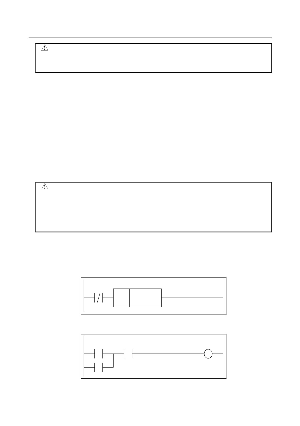
(4) Example of using the signals
(a) Example of calling a subprogram just before the ladder stops
R9015.1
(Z15.1)
SUB65
Pxxxx
CALL
(b) Example of forcibly turning off an output signal programmed on the first ladder level just
before the ladder stops
R9015.1
Input
(Z15.1)
Output
- 344 -

B-64485EN/01
6.INTERFACE BETWEEN CNC AND PMC
(c) Example of sending an execution-in-progress signal to the outside
Outputting the status of this signal as the DO signal (output address from the PMC) assigned to
the I/O Link causes the CNC unit to be interlocked with an external system.
CNC unit
Y0.0
R9015.1
I/O Link slave
(Z15.1)
Y0.0
I/O Link
- 345 -

6.INTERFACE BETWEEN CNC AND PMC
B-64485EN/01
6.3
PMC SPECIFICATIONS
6.3.1
Basic Specifications
Table 6.3.1 (a) Basic specifications of the PMCs for the Series 30i/31i/32i-A
DCS PMC
Function
1st ~ 5th- path PMC
(Note1)
PMC Memory Type(Note2)
1st PMC
(Note3)
PMC Memory-B
PMC Memory-C
PMC Memory-D
2nd~5th PMC
PMC Memory-A
PMC Memory-B
PMC Memory-C
Common PMC Memory with 1st PMC
Programming language
Ladder
Ladder
Step sequence(Note4)
Function block
Function block
Number of ladder levels
3
2 (Note5)
Level 1 execution period (Note6)
4 or 8 msec
8 msec
Processing power
• Basic instruction processing speed(transition
9.1 nsec/step
1 μsec/step
contact) (Note7)
• Basic instruction processing
310 nsec/step
19.2 μ sec/step
speed(Positive/Negative transition contact)
Program capacity (Note8)
• Ladder
Up to about 300,000 steps
Up to about 3,000 steps
• Symbol & Comment
At least 1KB
At least 1KB
• Message
At least 8KB
At least 8KB
Instructions
• Basic instructions
24
24
• Functional instructions (Note9)
218 (230)
207 (230)
Instructions(When the expanded PMC ladder
instruction function is invalid)
• Basic instructions
14
14
• Functional instructions (Note9)
93 (105)
85 (105)
CNC interface
• Inputs (F)
768 bytes × 10(Note10)
768 bytes
• Outputs (G)
768 bytes × 10(Note10)
768 bytes
DI/DO
• I/O Link (Note 11,12)
• I/O Link i (Note 13~16)
• Inputs (X)
Up to 4,096 points (Note17)
Up to 64 points
• Outputs (Y)
Up to 4,096 points (Note17)
Up to 64 points
Symbol & Comment (Note18)
• Number of symbol characters
40
40
• Number of comment characters (Note19)
255
255
Program storage area (Flash ROM) (Note20)
Max. 5MB (total of all sequence
128KB
programs of PMC paths and PMC
message multi-language data)
- 346 -
B-64485EN/01
6.INTERFACE BETWEEN CNC AND PMC
NOTE
1 This PMC is used for Dual Check Safety (DCS) and handles the safety related
signals.
2 As for the setting the PMC memory type, see PMC Programming Manual
(B-64513EN).
3 There is no variation of PMC memory type in DCS PMC.
4 The Step Sequence is unavailable in 2nd to 5th PMC.
5 A program can be created on level 3 to maintain source-level compatibility with
programs for other models, but it is not executed.
6 CNC parameter is used to specify a level-1 execution period. Note, however, that it
is impossible to specify a level-1 execution period for each PMC separately.
7 It is the processing speed of contact other than Positive/Negative transition contact.
8 The maximum overall program size (including the maximum number of ladder
steps, symbols/ comments, and messages) varies depending on option settings.
See PMC Programming Manual (B-64513EN) for details.
9 For the number of functional instructions, each parenthesized number indicates the
number of all functional instructions, and each non-parenthesized number, the
number of valid functional instructions.
10 It is possible to specify which program is used to control a specific CNC system.
11 You can use up to three I/O Link channels (3,072 input points and 3,072 output
points).
12 The transferred cycle of the signals from I/O Link depends on the combination with
each PMC and each I/O Link channel.
13 You can use up to two I/O Link i channels (4,096 input points and 4,096 output
points).
14 I/O Link i can assign I/O devices for plural PMC paths in the one channel.
15 I/O Link i can be used for the channel 1 and the channel 2.
16 When you use the I/O Link i, you can select either the normal mode (2ms) or the
high-speed mode (0.5ms) of the transfer cycle of signals for every group unit
17 You can use both I/O Link and I/O Link i in a CNC system. In the case of the
system, you can use up to 4,096 input points and 4096 output points.
18 These are the number for extended symbol and comment character. The number of
basic symbol character is 16 and the number of comment character is 30.
19 This number is the number of single-byte characters. When you use double-byte
characters as a comment, the number becomes half.
20 The capacity of the program storage area varies depending on option settings.
See PMC Programming Manual (B-64513EN) for details.
- 347 -

6.INTERFACE BETWEEN CNC AND PMC
B-64485EN/01
Table 6.3.1 (b) Basic specifications of each PMC Memory Type
1st to 5th PMC
DCS PMC
Function
PMC
PMC
PMC
PMC
(Note 1)
Memory-A
Memory-B
Memory-C
Memory-D
PMC Memory
• Internal relay (R)
1,500 bytes
8,000 bytes
16,000 bytes
60,000 bytes
1,500 bytes
• System Relay
500 bytes
500 bytes
500 bytes
500 bytes
500 bytes
(R9000 or Z)
• Extra relay (E) (Note2)
10,000 bytes
10,000 bytes
10,000 bytes
10,000 bytes
(Note 3)
• Message display (A)
⋅ Display requests
2,000 points
2,000 points
4,000 points
6,000 points
(Note 4)
⋅ Status displays
2,000 points
2,000 points
4,000 points
6,000 points
(Note 4)
• Nonvolatile memory
• Timer (T)
⋅ Variable timer
80 bytes
500 bytes
1,000 bytes
1,000 bytes
80 bytes
(40 pieces)
(250 pieces)
(500 pieces)
(500 pieces)
(40 pieces)
⋅ Variable timer
80 bytes
500 bytes
1,000 bytes
1,000 bytes
80 bytes
precision
(40 pieces)
(250 pieces)
(500 pieces)
(500 pieces)
(40 pieces)
• Counter (C)
⋅ Variable counter
80 bytes
400 bytes
800 bytes
1200 bytes
80 bytes
(20 pieces)
(100 pieces)
(200 pieces)
(300 pieces)
(20 pieces)
⋅ Fixed counter
40 bytes
200 bytes
400 bytes
600 bytes
40 bytes
(20 pieces)
(100 pieces)
(200 pieces)
(300 pieces)
(20 pieces)
• Keep relay (K)
⋅ User area
20 bytes
100 bytes
200 bytes
300 bytes
20 bytes
⋅ System area
100 bytes
100 bytes
100 bytes
100 bytes
100 bytes
• Data table (D)
3,000 bytes
10,000 bytes
20,000 bytes
60,000 bytes
3,000 bytes
(Note 5)
(Note 5)
• Step sequence
⋅ Step number (S)
(None)
2,000 bytes
2,000 bytes
2,000 bytes
(None)
Functional instructions
• Variable timers (TMR)
40 pieces
250 pieces
500 pieces
500 pieces
40 pieces
• Fixed timers
100 pieces
500 pieces
1,000 pieces
1,500 pieces
100 pieces
(TMRB/TMRBF)
• Variable counters
20 pieces
100 pieces
200 pieces
300 pieces
20 pieces
(CTR)
• Fixed counters (CTRB)
20 pieces
100 pieces
200 pieces
300 pieces
20 pieces
• Rising/Falling edge
256 pieces
1,000 pieces
2,000 pieces
3,000 pieces
256 pieces
detection (DIFU/DIFD)
• Labels (LBL)
9,999 pieces
9,999 pieces
9,999 pieces
9,999 pieces
9,999 pieces
• Subprograms (SP)
512 pieces
5,000 pieces
5,000 pieces
5,000 pieces
512 pieces
- 348 -

B-64485EN/01
6.INTERFACE BETWEEN CNC AND PMC
NOTE
1 This PMC is used for Dual Check Safety function (option).
2 The extra relay is common memory for the multi-PMC function. This means that
its size covers all of PMCs. Moreover, It is possible to use the extra relay as
nonvolatile memory by the option.
3 No extra relay is available for DCS PMC.
4 The message display relay is ineffective in DCS PMC because the message
display function is unavailable in it.
5 Under the configuration having two or more paths of PMC Memory-C or one
path of PMC Memory-D, please specify the "Nonvolatile PMC data table area
expansion 40KB" option. If this option is not added, the expanded data table
area (D10000~) is not kept after rebooting CNC. Refer to PMC Programming
Manual (B-64513EN) for details.
- 349 -

6.INTERFACE BETWEEN CNC AND PMC
B-64485EN/01
6.3.2
Addresses
Table 6.3.2 (a) PMC Addresses list (1)
1st to 5nd PMC
DCS PMC
Signals
Symbol
PMC memory
PMC memory
PMC memory
PMC memory
(Note 1)
A
B
C
D
Input signal to the PMC
X
X0~X127
X0~X127
X0~X127
X0~X127
X0~X127
from the machine
X200~X327
X200~X327
X200~X327
X200~X327
X400~X527
X400~X527
X400~X527
X400~X527
X600~X727
X600~X727
X600~X727
X600~X727
X1000~X1127
X1000~X1127
X1000~X1127
X1000~X1127
(Note 2)
(Note 2)
(Note 2)
(Note 2)
Output signal from the
Y
Y0~Y127
Y0~Y127
Y0~Y127
Y0~Y127
Y0~Y127
PMC to the machine
Y200~Y327
Y200~Y327
Y200~Y327
Y200~Y327
Y400~Y527
Y400~Y527
Y400~Y527
Y400~Y527
Y600~Y727
Y600~Y727
Y600~Y727
Y600~Y727
Y1000~Y1127
Y1000~Y1127
Y1000~Y1127
Y1000~Y1127
(Note 2)
(Note 2)
(Note 2)
(Note 2)
Input signal to the PMC
F
F0~F767
F0~F767
F0~F767
F0~F767
F0~F767
from the CNC
F1000~F1767
F1000~F1767
F1000~F1767
F1000~F1767
F2000~F2767
F2000~F2767
F2000~F2767
F2000~F2767
F3000~F3767
F3000~F3767
F3000~F3767
F3000~F3767
F4000~F4767
F4000~F4767
F4000~F4767
F4000~F4767
F5000~F5767
F5000~F5767
F5000~F5767
F5000~F5767
F6000~F6767
F6000~F6767
F6000~F6767
F6000~F6767
F7000~F7767
F7000~F7767
F7000~F7767
F7000~F7767
F8000~F8767
F8000~F8767
F8000~F8767
F8000~F8767
F9000~F9767
F9000~F9767
F9000~F9767
F9000~F9767
Output signal from the
G
G0~G767
G0~G767
G0~G767
G0~G767
G0~G767
PMC to the CNC
G1000~G1767
G1000~G1767
G1000~G1767
G1000~G1767
G2000~G2767
G2000~G2767
G2000~G2767
G2000~G2767
G3000~G3767
G3000~G3767
G3000~G3767
G3000~G3767
G4000~G4767
G4000~G4767
G4000~G4767
G4000~G4767
G5000~G5767
G5000~G5767
G5000~G5767
G5000~G5767
G6000~G6767
G6000~G6767
G6000~G6767
G6000~G6767
G7000~G7767
G7000~G7767
G7000~G7767
G7000~G7767
G8000~G8767
G8000~G8767
G8000~G8767
G8000~G8767
G9000~G9767
G9000~G9767
G9000~G9767
G9000~G9767
Input signal from other
M
M0~M767
M0~M767
M0~M767
M0~M767
PMC path
Output signal to other
N
N0~N767
N0~N767
N0~N767
N0~N767
PMC path
- 350 -

B-64485EN/01
6.INTERFACE BETWEEN CNC AND PMC
Table 7.3.2(b) PMC Addresses list (2)
1st~5nd PMC
DCS PMC
Signals
Symbol
PMC memory
PMC memory
PMC memory
PMC memory
(Note 1)
A
B
C
D
Internal relay
R
R0~R1499
R0~R7999
R0~R15999
R0~R59999
R0~R1499
System relay
R / Z
R9000~R9499
R9000~R9499
Z0~Z499
Z0~Z499
R9000~R9499
Extra relay
E
E0~E9999
E0~E9999
0~E9999
E0~E9999
(Note 4)
(Note 3)
(Note 3)
(Note 3)
(Note 3)
Message display
A
⋅ Display request
A0~A249
A0~A249
A0~A499
A0~A749
A0~A249
⋅ Display status
A9000~A9249
A9000~A9249
A9000~A9499
A9000~A9749
A9000~A9249
Timer
T
⋅ Variable timer
T0~T79
T0~T499
T0~T999
T0~T999
T0~T79
⋅ Variable timer
T9000~T9079
T9000~T9499
T9000~T9999
T9000~T9999
T9000~T9079
precision (Note 5)
Counter
C
⋅ Variable counter
C0~C79
C0~C399
C0~C799
C0~C1199
C0~C79
⋅ Fixed counter
C5000~C5039
C5000~C5199
C5000~C5399
C5000~C5599
C5000~C5039
Keep relay
K
⋅ User area
K0~K19
K0~K99
K0~K199
K0~K299
K0~K19
⋅ System area
K900~K999
K900~K999
K900~K999
K900~K999
K900~K999
Data table
D
D0~D2999
D0~D9999
D0~D19999
D0~D59999
D0~D2999
(Note 6)
(Note 6)
Label
L
L1~L9999
L1~L9999
L1~L9999
L1~L9999
L1~L9999
Subprogram
P
P1~P512
P1~P5000
P1~P5000
P1~P5000
P1~P512
Step number (Step
S
(なし)
S1~S2000
S1~S2000
S1~S2000
(なし)
sequence)
NOTE
1 This PMC is used for Dual Check Safety function (option).
2 This area is reserved for PMC management software. Do not use it in user
programs.
3 This area is common memory for the multi-path PMC function. Each program
can write and read the same value in the area.
4 No extra relay is available for the Dual Check Safety PMC.
5 This area is used to specify the precision of a variable timer.
- Don't modify the value of active timer and its precision except for writing
same value.
- Don't set the value other than the following range.
- If above rules are violated, the behavior of the timer is not guaranteed.
The value of precision
0: Default (8msec or 4msec)
1:
1msec
2:
10msec
3:
100msec
4:
1sec
5:
1min
6 To save all area of the data table, the “Nonvolatile PMC data table area
expansion (40KB)” option may be necessary. See PMC Programming Manual
(B-64513EN) for details.
- 351 -
6.INTERFACE BETWEEN CNC AND PMC
B-64485EN/01
6.4
OPERATING THE PMC SCREEN
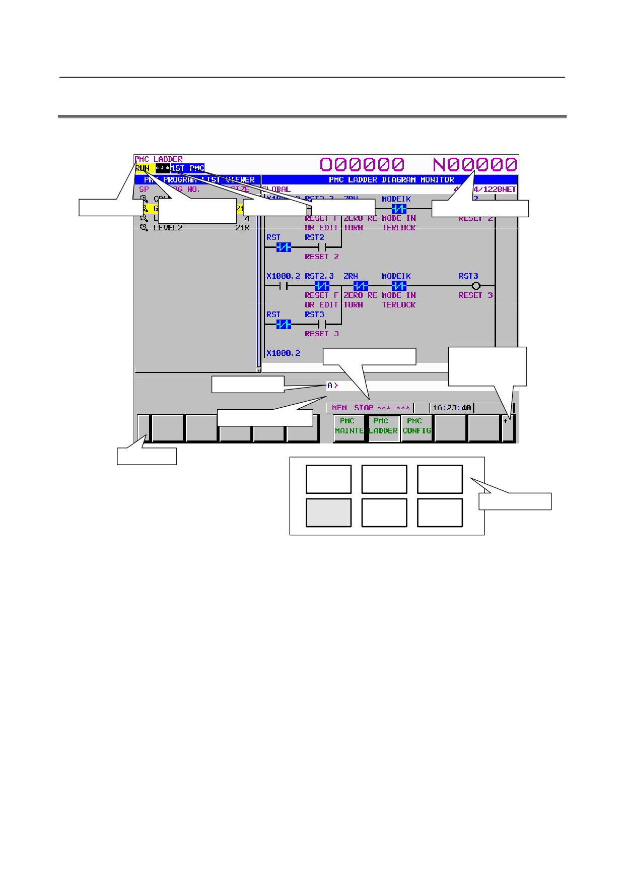
The basic configuration of the PMC screen is described below.
Screen title
Ladder
PMC alarm
PMC path
NC program number
execution status
NC status indication
[+]
Soft key page
turning key
Key entry line
Message display line
Return key
POS
PROG
OFFSET
SETTING
Function keys
SYSTEM
MESSAGE
GRAPH
• Screen title:
Displays the name of a specific submenu of the PMC.
• Ladder execution status:
Displays the execution status of the ladder program.
• PMC alarm:
Indicates whether any PMC alarm is occurring.
• PMC path:
Displays the currently selected PMC.
• NC program number:
Displays the number of the currently selected NC program.
• Key entry line:
Line for entering a numerical value or character key string.
• Message display line:
Displays an error or warning message.
• NC status indication:
Displays the NC mode, the execution status of the NC program, the
currently selected NC path number.
• Return key:
Used to switch from the PMC operation menu to a specific PMC
submenu or from a specific PMC submenu to the main menu of the
PMC.
• Soft key page turning key: Used to turn soft key pages.
About the PMC screen
When you click the "SYSTEM" function key and then turn the soft key page by clicking the soft key [+],
the main menu of the PMC is displayed.
The PMC main menu offers the following three types of submenus, which are respectively used for
specific purposes.
• PMC maintenance
- 352 -
B-64485EN/01
6.INTERFACE BETWEEN CNC AND PMC
• PMC ladder
• PMC configuration
Each of these PMC submenus is explained below.
(1) PMC maintenance menu
This menu displays the screens related to the maintenance of the PMC, such as those for PMC signal
status monitoring and traces and for PMC data display and editing.
(2) PMC ladder menu
This menu displays the screens related to the display and editing of the ladder program.
(3) PMC configuration menu
This menu displays the screens related to the display and editing of the data other than the ladder
constituting the sequence program, as well as the screen for setting the PMC functions.
This manual briefly describes the screen of each of the PMC maintenance and PMC ladder menus. For
detailed descriptions and the PMC configuration menu, refer to "PMC Programming Manual
(B-64513EN)."
- 353 -
6.INTERFACE BETWEEN CNC AND PMC
B-64485EN/01
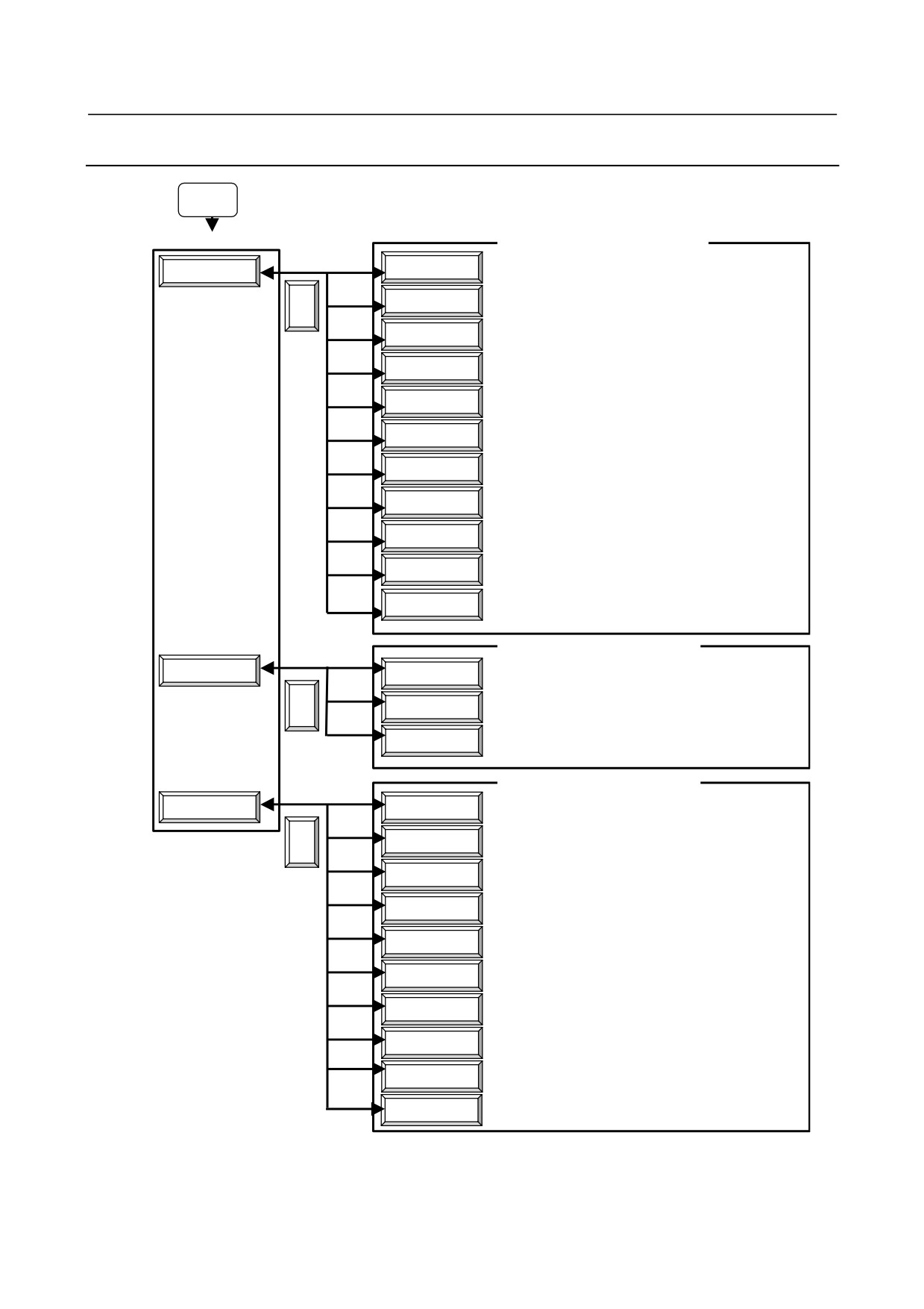
6.4.1
Transition of the PMC Screens
SYSTEM
PMC main menu
PMC maintenance submenu
STATUS
Signal status screen
(See Subsection 6.5.1.)
PMC MAINTE
I/O DEVICE
I/O device monitor screen
(See Subsection 6.5.8.)
<
PMC ALARM
PMC alarm screen
(See Subsection 6.5.2.)
I/O
Data I/O screen
(See Subsection 6.5.7.)
TIMER
PMC parameter (timer) screen
(See Subsection 6.5.3.)
COUNTR
PMC parameter (counter) screen
(See Subsection 6.5.4.)
PMC parameter (keep relay)
KEEP RELAY
(See Subsection 6.5.5.)
screen
DATA
PMC parameter (data table) screen
(See Subsection 6.5.6.)
TRACE
Signal trace screen
(See Subsection 6.5.9.)
Signal trace (parameter setting)
TRACE SETING
(See Subsection 6.5.10.)
screen
II/O DIAGNOSIS screen
(See Subsection 6.5.12.)
I/O DGN
PMC ladder submenu
PMC LADDER
Program list screen
(See Subsection 6.6.1.)
LIST
Ladder display/editing screen
(See Subsection 6.6.2.)
<
LADDER
Duplicate coil check screen
DUP. CHECK
PMC configuration submenu
PMC CONFIG
TITLE
Title display/editing screen
<
CONFIG PARAM
Configuration parameter screen
Setting screens (general, message shift,
SETING
I/O link assignment data selection,
override)
PMC STATUS
PMC status screen (multi-PMC switch)
System parameter display/editing
SYSTEM PARAM
screen
MODULE
I/O module display/editing screen
Symbol and comment display/editing
SYMBOL
screen
MESAGE
Message display/editing screen
Online monitoring parameter setting
ONLINE
screen
I/O configuration viewer/editor screen
I/O Link i
(I/O Link i assignment)
- 354 -
B-64485EN/01
6.INTERFACE BETWEEN CNC AND PMC
6.5
PMC DIAGNOSIS AND MAINTENANCE SCREENS ([PMC
MAINTE])
6.5.1
Monitoring PMC Signal Status ([STATUS] Screen)
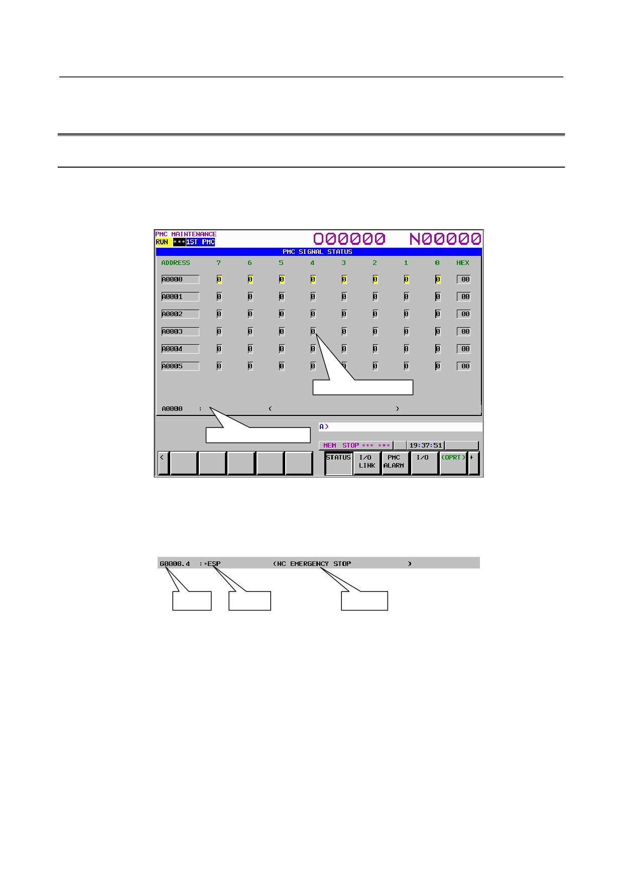
The SIGNAL STATUS screen displays the data at all addresses specified in the program. The data of
each address consists of a bit pattern (0s and/or 1s) and a hexadecimal or decimal number at the rightmost
position on a byte-by-byte basis.
Signal status display area
Additional information line
Fig. 6.5.1 (a) Signal status screen
The additional information line at the bottom of the screen displays the symbol and comment of the
address on which the cursor is placed. When the cursor is placed on a byte, the byte symbol and comment
are displayed.
Address
Symbol
Comment
Table contents
• ADDRESS: Address referenced by a sequence program
•
0 to 7:
Data at each bit position
•
HEX:
Display of each byte in hexadecimal
•
DEC:
Display of each byte in decimal
Operation procedure
(1) Press the soft key [STATUS]. The screen shown above appears.
(2) Key in an address whose data to be displayed, then press the soft key [SEARCH].
(3) The data starting at the input address is displayed as a bit pattern.
(4) To display the data at another address, press the cursor keys, page keys, or soft key [SEARCH].
(5) To modify the status of a signal, switch to the forced I/O screen by pressing the soft key [FORCE].
- 355 -
6.INTERFACE BETWEEN CNC AND PMC
B-64485EN/01
NOTE
The soft key [FORCE] is displayed and usable when the forced I/O function is
enabled. For details, see PMC PROGRAMMING MANUAL (B-64513EN).
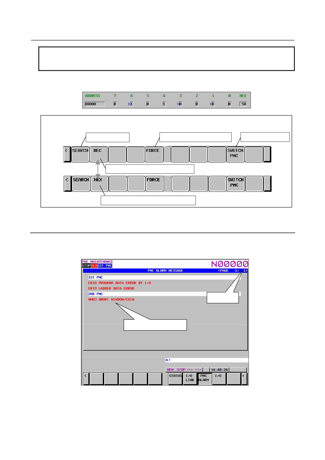
(6) On the forced I/O screen, an overridden X signal or Y signal is prefixed by a greater-than sign (>) to
indicate the setting of override.
Soft keys on the Signal Status screen
Address search
Switching to the forced I/O screen
PMC path switching
Switching to display in decimal
Switching to display in hexadecimal
Fig. 6.5.1 (b) Soft keys on the SIGNAL STATUS screen
6.5.2
Checking PMC Alarms ([PMC ALARM] Screen)
On this screen, an alarm message output from the PMC is displayed. To move to the PMC alarm screen,
press the soft key [PMC ALARM].
Page display
Alarm message display area
Fig. 6.5.2 (a) PMC alarm screen
In the alarm message display area, an alarm message output from the PMC is displayed. When many
alarm messages are output to two or more pages, the page keys can be used to switch from one page to
another.
- 356 -
B-64485EN/01
6.INTERFACE BETWEEN CNC AND PMC
In the page display area to the right of the title, the number of the page currently displaying messages is
indicated.
For information about messages displayed, see Appendix A “Alarm List.”
6.5.3
Setting and Displaying Variable Timers ([TIMER] Screen)
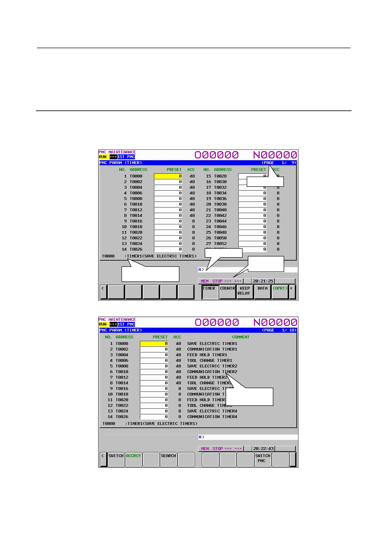
This screen is used to set and display timer values for functional instruction variable timers (TMR:SUB 3).
This screen can be used in one of two modes: the simple display mode and the comment display mode.
To move to the TIMER screen, press the soft key [TIMER].
Page display
Key input line
Message
display line
Additional information
line
Fig. 6.5.3 (a) Time screen: simple display mode
Comment display
area
Fig. 6.5.3 (b) Time screen: comment display mode
Table contents
• NO.:
Timer number specified for a functional instruction timer.
• ADDRESS:
Address referenced by a sequence program
- 357 -
6.INTERFACE BETWEEN CNC AND PMC
B-64485EN/01
• PRESET:
Timer setting value
• ACC:
Timer accuracy
• COMMENT:
T address comment
In the PRESET column, timer setting values are displayed. When the timer accuracy is 8, 48, 1, 10, or
100 ms, only a numeric value is displayed. When the timer accuracy is the second or minute, a time value
is displayed using H, M, and S with the separator "_" used to delimit one unit from another as follows:
aaH_bbM_ccS
In the ACC column, timer accuracy values are displayed. The table below indicates the time setting
values and notation of each accuracy value.
Timer No. (Note)
Accuracy notation
Minimum time setting
Maximum time setting
1 to 8
48 (initial value)
48 ms
1572.8 seconds
9 to 250
8 (initial value)
8 ms
262.1 seconds
1 to 250
1
1 ms
32.7 seconds
1 to 250
10
10 ms
327.7 seconds
1 to 250
100
100 ms
54.6 minutes
1 to 250
S
1 second
546 minutes
1 to 250
M
1 minute
546 hours
NOTE
Above table is for PMC Memory-B. the timer number is 1 to 40 in PMC
Memory-A and DCSPMC, and 1 to 500 in PMC Memory-C/D.
The additional information line at the bottom of the screen displays the symbol and comment of the
address on which the cursor is placed.
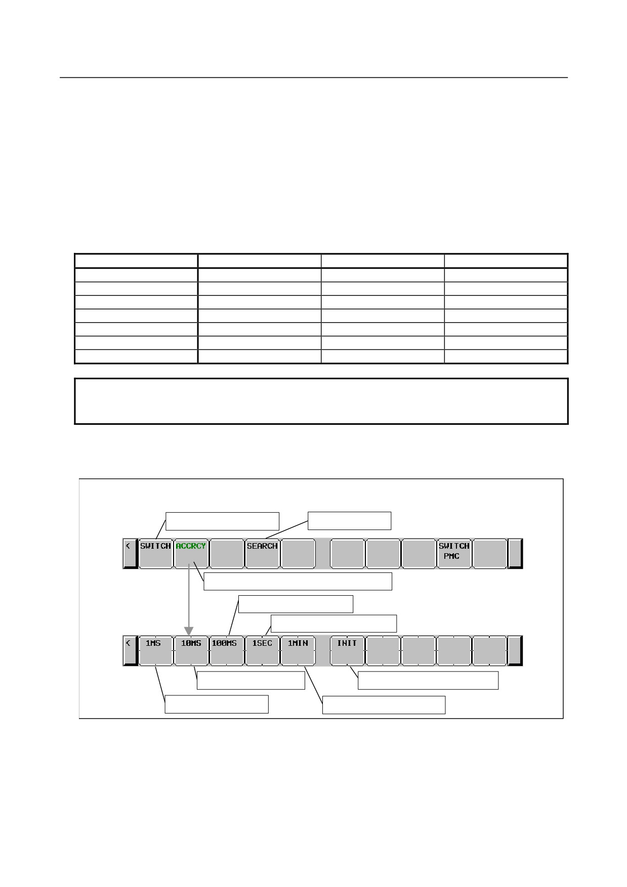
Soft keys on the TIMER screen
T address search
Switching the display mode
Switching to the soft keys for accuracy setting
Setting accuracy to 100 ms
Setting accuracy to 1 second
Setting accuracy to 10 ms
Setting accuracy to an initial value
Setting accuracy to 1 ms
Setting accuracy to 1 minute
- 358 -
B-64485EN/01
6.INTERFACE BETWEEN CNC AND PMC
6.5.4
Setting and Displaying Counter Values ([COUNTR] Screen)
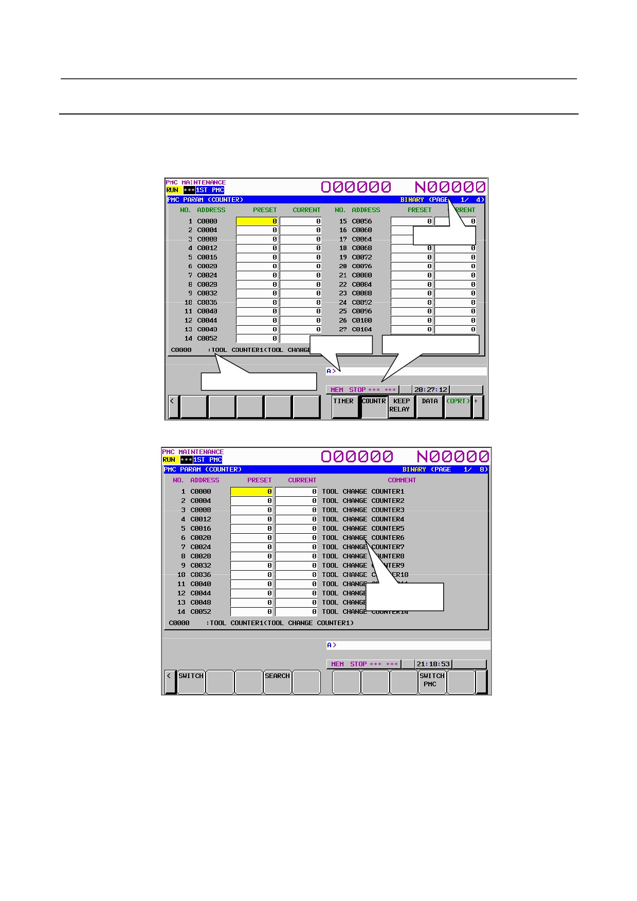
This screen is used to set and display the maximum and current counter values for functional instruction
counters (CTR: SUB 5). This screen can be used in one of two modes: the simple display mode and the
comment display mode. To move to the COUNTER screen, press the soft key [COUNTR].
Page display
Key input line
Message display line
Additional information line
Fig. 6.5.4 (a) Counter screen: simple display mode
Comment display
area
Fig. 6.5.4 (b) Counter screen: comment display mode
Table contents
• NO.:
Counter number specified for a functional instruction counter
• ADDRESS:
Address referenced by a sequence program
• PRESET:
Maximum counter value (a minimum counter value is specified by a counter
instruction)
• CURRENT: Current counter value
• COMMENT: Comment on the C address of a setting value
- 359 -
6.INTERFACE BETWEEN CNC AND PMC
B-64485EN/01
The additional information line at the bottom of the screen displays the symbol and comment of the
address on which the cursor is placed. If the cursor is placed on a PRESET value, the symbol and
comment of the address of the PRESET value are displayed. If the cursor is placed on a CURRENT value,
the symbol and comment of the address of the CURRENT value are displayed.
Counter types and maximum values
Counter type
PRESET maximum value
CURRENT maximum value
BINARY
32767
32767
BCD
9999
9999
Soft keys on the COUNTER screen
Display mode switching
C address search
6.5.5
Setting and Displaying Keep Relays ([KEEP RELAY] Screen)
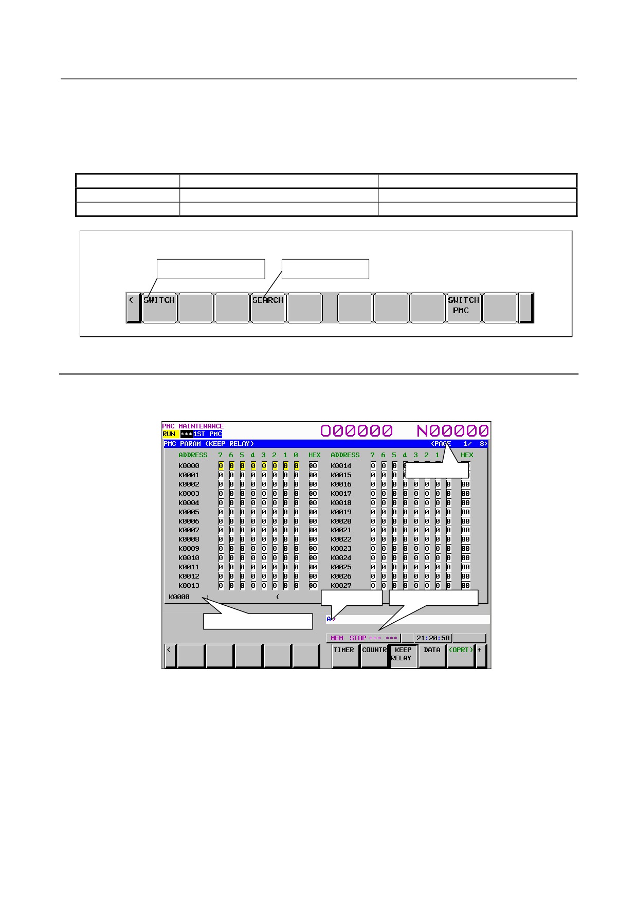
This screen is used for setting and displaying the Keep Relays. To move to the KEEP RELAY screen,
press the [KEEP RELAY] soft key.
Page display
Key input line
Message display line
Additional information line
Fig. 6.5.5 (a) Keep relay screen
Contents of the table
• ADDRESS: Address referred by sequence Program
•
0 to 7:
Contents of each bit
•
HEX:
Value of the byte data in hexadecimal notation
The additional information line at the bottom of the screen displays the symbol and comment of the
address on which the cursor is placed. When the cursor is placed on a byte, the byte symbol and comment
are displayed.
Since Keep Relay is nonvolatile memory, the contents are not lost even if you turn off the power.
The Keep Relay area consists of parts as follows.
- 360 -
B-64485EN/01
6.INTERFACE BETWEEN CNC AND PMC
30i/31i/32i-B
PMC memory
PMC memory
PMC memory
PMC memory
Dual check safety
Type A
Type B
Type C
Type D
PMC (option)
User area
K0~K19
K0~K99
K0~K199
K0~K299
K0~K19
Area for management
K900~K999
K900~K999
K900~K999
K900~K999
K900~K999
software
CAUTION
If the area for the PMC management software is protected by the programmer
protection function, the area is not displayed on the KEEP RELAY screen. For
details, see PMC PROGRAMMING MANUAL (B-64513EN).
6.5.6
Setting and Displaying Data Tables ([DATA] Screen)
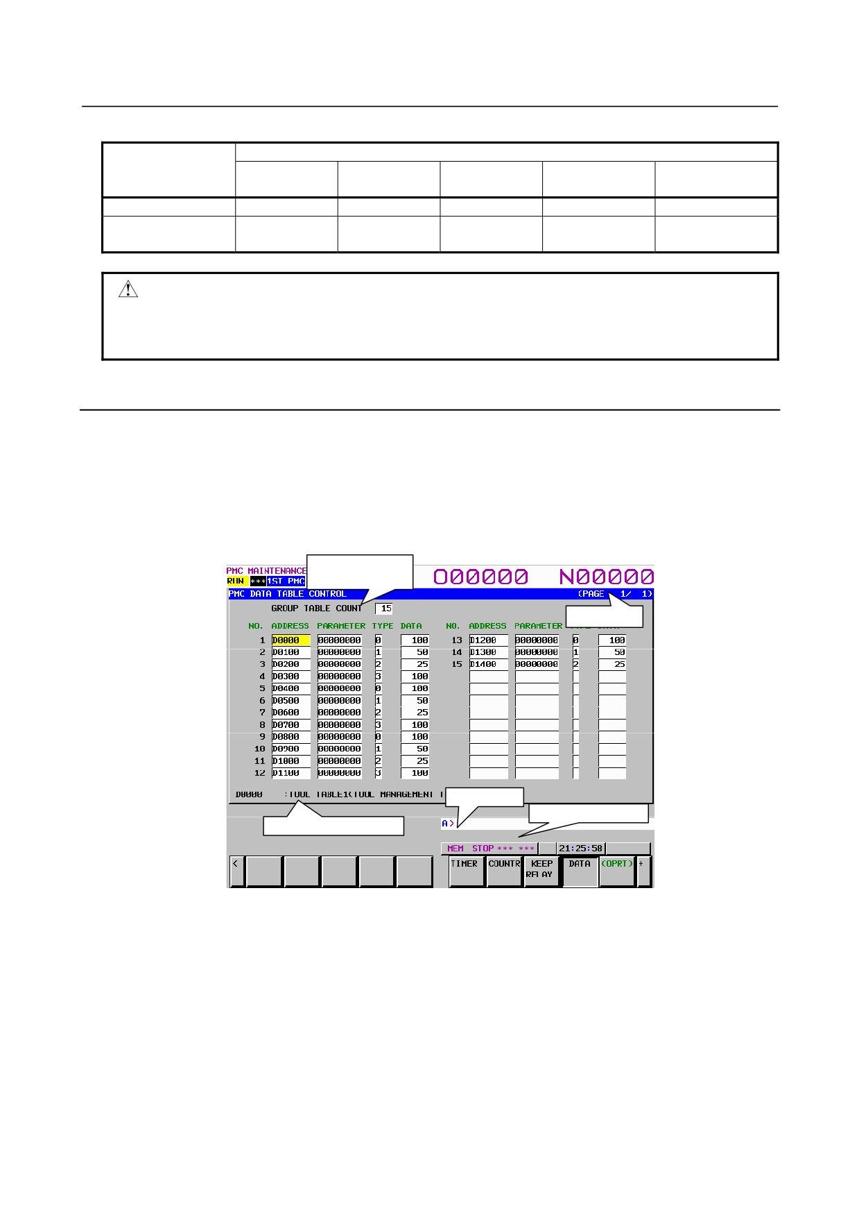
There are two data table types (data table control data table and data table). To move to the data screen,
press the soft key [DATA].
(1) DATA TABLE CONTROL screen ([LIST] screen)
Pressing the soft key
[DATA] displays the DATA TABLE CONTROL screen for data table
management. This screen can be used in one of two modes: the simple display mode and the
comment display mode.
Display of the
number of groups
Page display
Key input line
Message display line
Additional information line
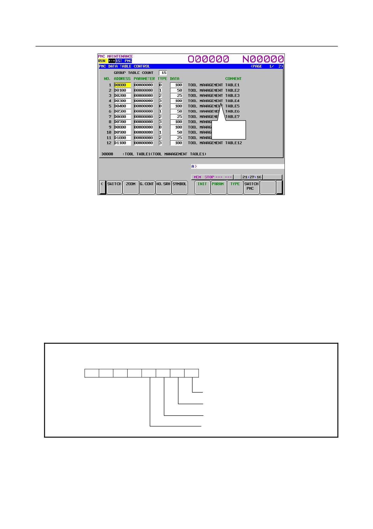
Fig. 6.5.6 (a) Data table control data screen: simple display mode
- 361 -
6.INTERFACE BETWEEN CNC AND PMC
B-64485EN/01
Comment
display area
Fig. 6.5.6 (b) Data table control data screen: comment display mode
Table contents
• GROUP TABLE COUNT: Number of data items in the data table
• NO.:
Group number
• ADDRESS:
Data table start address
• PARAMETER:
Data table control parameter
• TYPE:
Data length (0 = 1 byte, 1 = 2 bytes, 2 = 4 bytes, 3 = bit)
• DATA:
Number of data items in each data table
• COMMENT:
Comment on the start D address of each group
The additional information line at the bottom of the screen displays the symbol and comment of the
address on which the cursor is placed. When the cursor is placed on the PARAMETER, TYPE, or DATA
column, the current setting is displayed.
The ADDRESS column displays the start address of a data table. Multiple groups may share an address.
When the soft key [SYMBOL] is pressed, the symbol of the start address is displayed.
NOTE
The data table control parameters have the following meanings:
#7
#6
#5
#4
#3
#2
#1
#0
0: Binary format
1: BCD format (Bits 2 and 3 are invalid.)
0: Without input protection
1: With input protection
0: Binary or BCD format (Bit 0 is valid.)
1: Hexadecimal format (Bits 0 and 3 are invalid.)
0: Signed (valid only when bits 0 and 2 are set to 0)
1: Unsigned (valid only when bits 0 and 2 are set to 0)
- 362 -
B-64485EN/01
6.INTERFACE BETWEEN CNC AND PMC
NOTE
1 When data table control data is protected by the programmer protection function,
the data table control data screen is not displayed. For details, see PMC
PROGRAMMING MANUAL (B-64513EN).
2 When PMC parameters are output using the I/O screen (see Subsection 7.5.7,
“Data Input/Output ([I/O] Screen)”), only the data of an address D area set in the
data table control data is output from the data table screen. The data of an
address D area not set in the data table control data is not output.
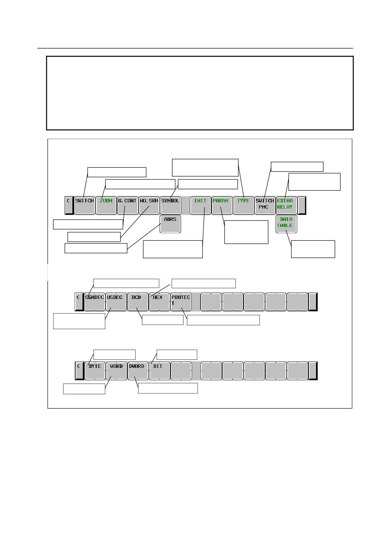
Soft keys on the DATA TABLE CONTROL screen
Switching to the soft keys for
PMC path switching
data size setting
Display mode switching
Switching to Extra
Switching to the zoom screen
Symbol display switching
relay screen
Input of the number of groups
Switching to the
soft keys for
Group number search
parameter setting
Data table control data
Switching to Data
Address display switching
initialization
table screen
Soft keys for parameter setting
Setting for signed decimal
Setting for hexadecimal
Setting for unsigned
Setting for BCD
Protection state modification
decimal
Soft keys for data size setting
Setting for byte
Setting for bit
Setting for word
Setting for double word
- 363 -
6.INTERFACE BETWEEN CNC AND PMC
B-64485EN/01
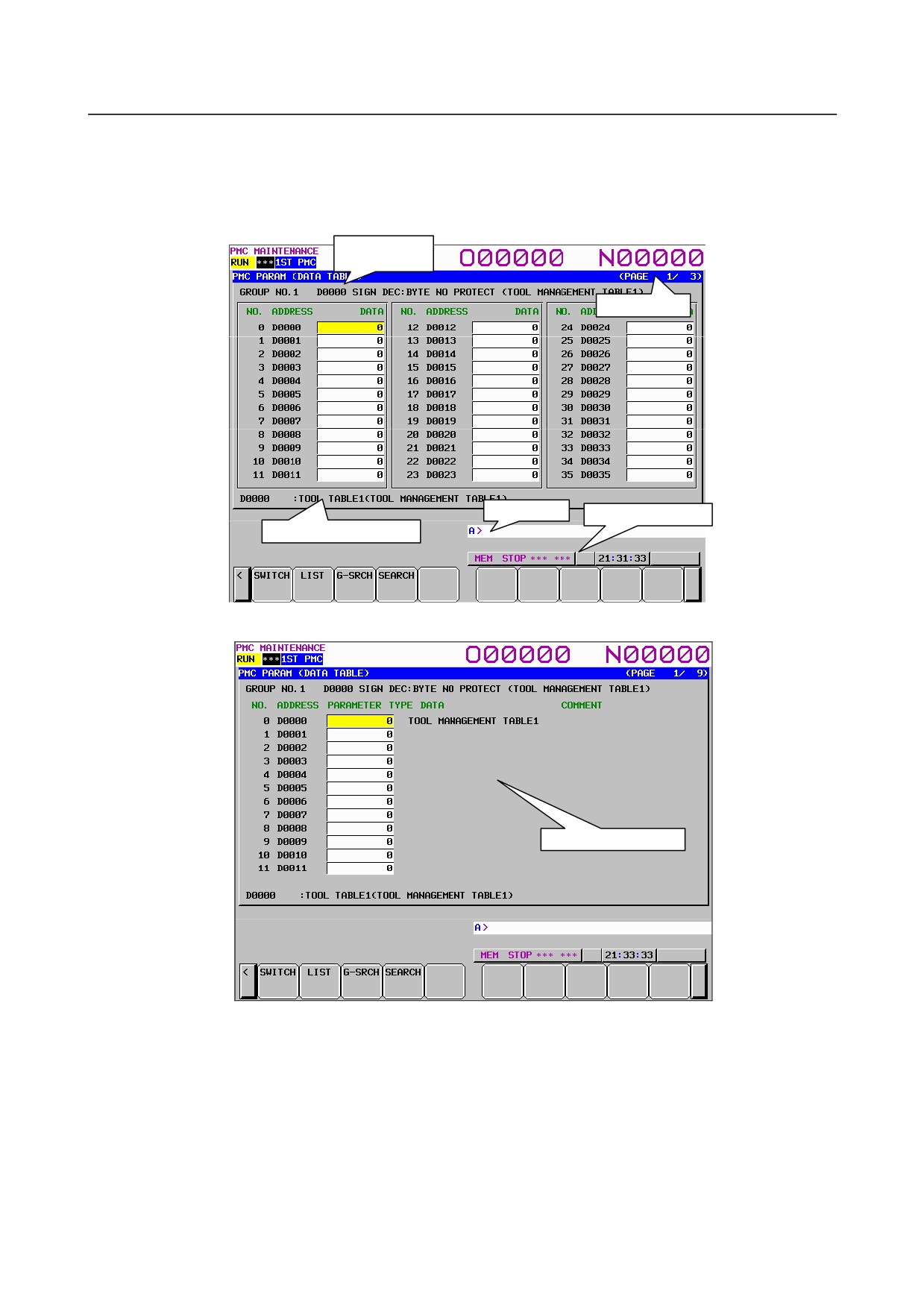
(2) DATA TABLE screen ([ZOOM] screen)
If the data table control data is specified, clicking the soft key [ZOOM] on the data table control data
screen displays the data table setting screen. This screen can be used in one of three modes: the
simple display mode, the comment display mode, and the bit display mode.
Group
information line
Page display
Key input line
Message display line
Additional information line
Fig. 6.5.6 (c) Data table screen: simple display mode
Comment display area
Fig. 6.5.6 (d) Data table screen: comment display mode
- 364 -
B-64485EN/01
6.INTERFACE BETWEEN CNC AND PMC
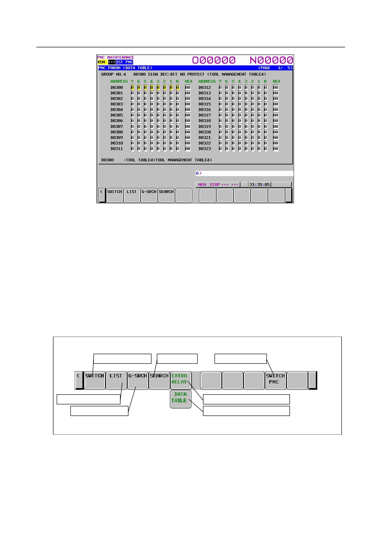
Fig. 6.5.6 (e) Data table screen: bit display mode
Table contents
• ADDRESS:
Address used by the sequence program
• DATA:
Data value of data table
• COMMENT:
Comment on the D address
•
0 to 7:
Data of each bit
•
HEX:
Display of each byte in hexadecimal
The group information line at the top of the screen displays a group number, group start address, settings,
and comment on the start address.
The additional information line at the bottom of the screen displays the symbol and comment of the
address on which the cursor is placed. In the bit display mode, a bit symbol and comment, or a byte
symbol and comment are displayed, depending on the cursor position.
Soft keys on the DATA TABLE screen
Display mode switching
Address search
Switching PMC path
Switching to the list screen
Switching to the Extra relay screen
Group number search
Switching to the Data table screen
- 365 -
6.INTERFACE BETWEEN CNC AND PMC
B-64485EN/01
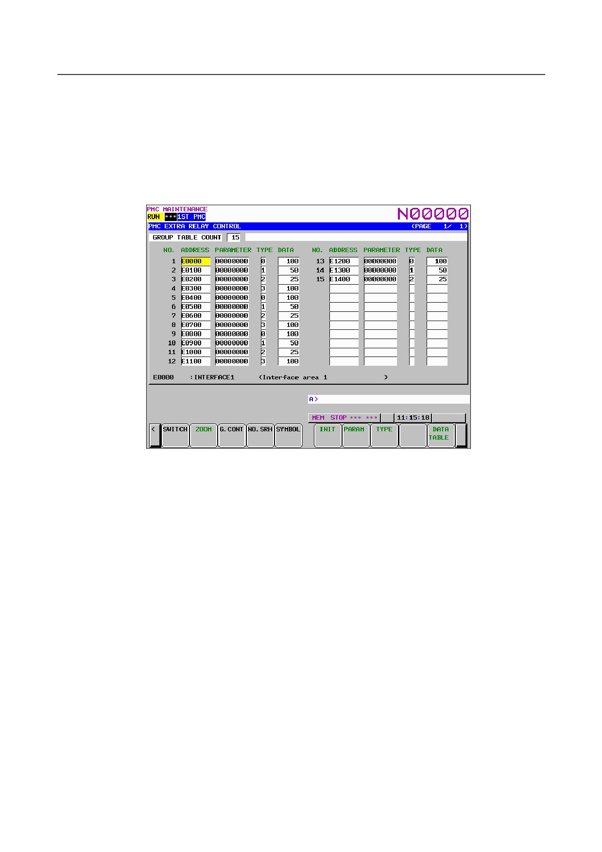
EXTRA RELAY CONTROL screen ([LIST] screen)
To switch to the EXTRA RELAY CONTROL screen in which you can manage the extra relay tables, use
[EXTRA RELAY] soft key in DATA TABLE CONTROL screen.
The operation of this screen is similar to the DATA TABLE CONTROL screen. See “DATA TABLE
CONTROL screen ([LIST] screen)” for the detail of the operations.
To make it easy to distinguish the EXTRA RELAY CONTROL screen from DATA TABLE CONTROL
screen, the EXTRA RELAY CONTROL screen has white background at the line of “GROUP TABLE
COUNT”.
Fig. 6.5.6 (f) EXTRA RELAY CONTROL screen: simple display mode
- 366 -
B-64485EN/01
6.INTERFACE BETWEEN CNC AND PMC
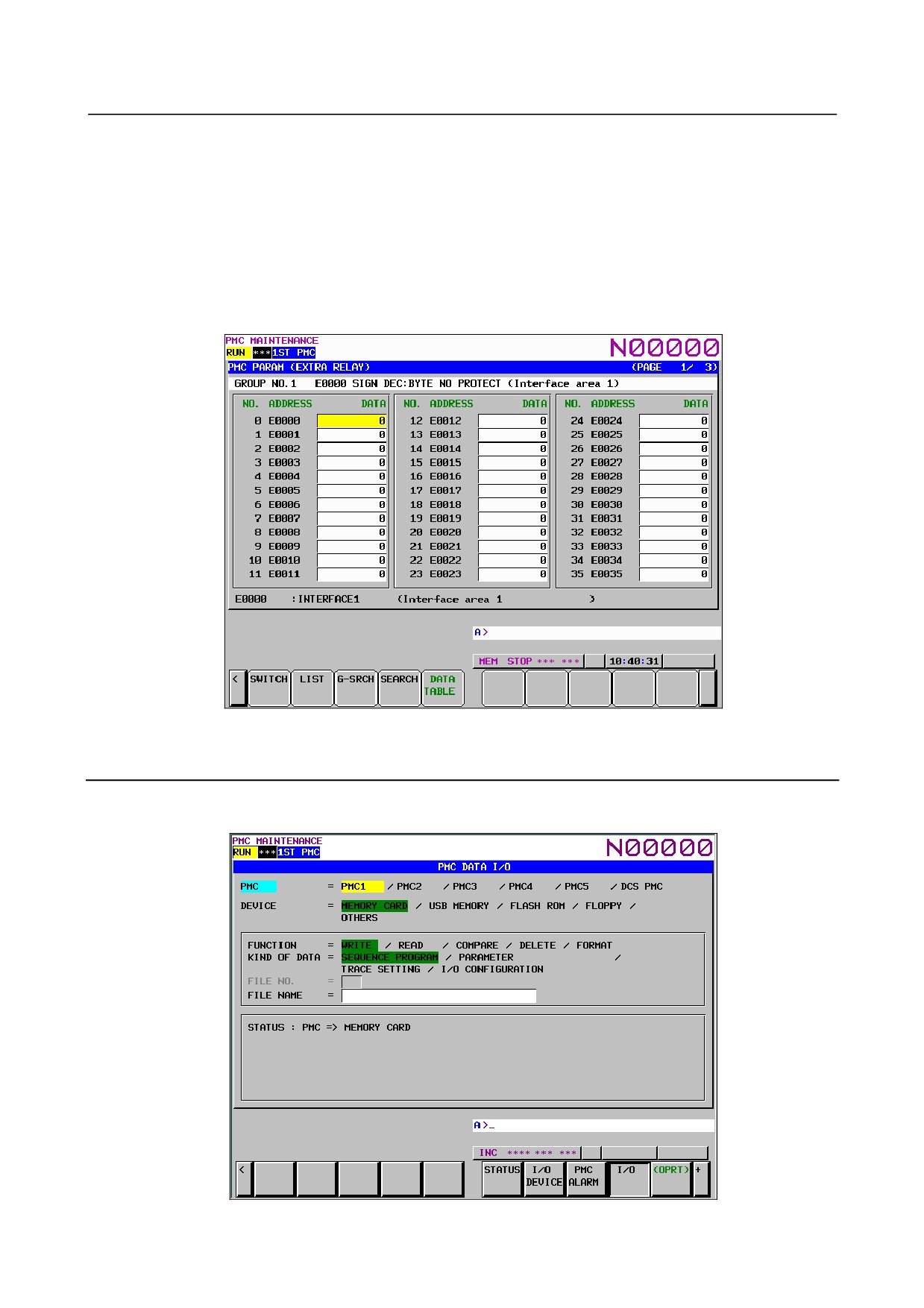
EXTRA RELAY screen ([ZOOM] screen)
When the extra relay control data are properly set, pressing [ZOOM] soft key at EXTRA RELAY
CONTROL screen leads you to the EXTRA RELAY screen. Similarly to the DATA TABLE screen,
this screen can show the contents of extra relays in three display modes; the simple display mode, the
comment display mode, and the bit display mode.
The operation of this screen is similar to the DATA TABLE screen. See “DATA TABLE screen
([ZOOM] screen)” for the detail of the operations.
To make it easy to distinguish the EXTRA RELAY screen from DATA TABLE screen, the
EXTRARELAY screen has white background at the line of the group information.
Fig. 6.5.6 (g) EXTRA RELAY screen: simple display mode
6.5.7
Data Input/Output ([I/O] Screen)
To move to the I/O screen, press the soft key [I/O].
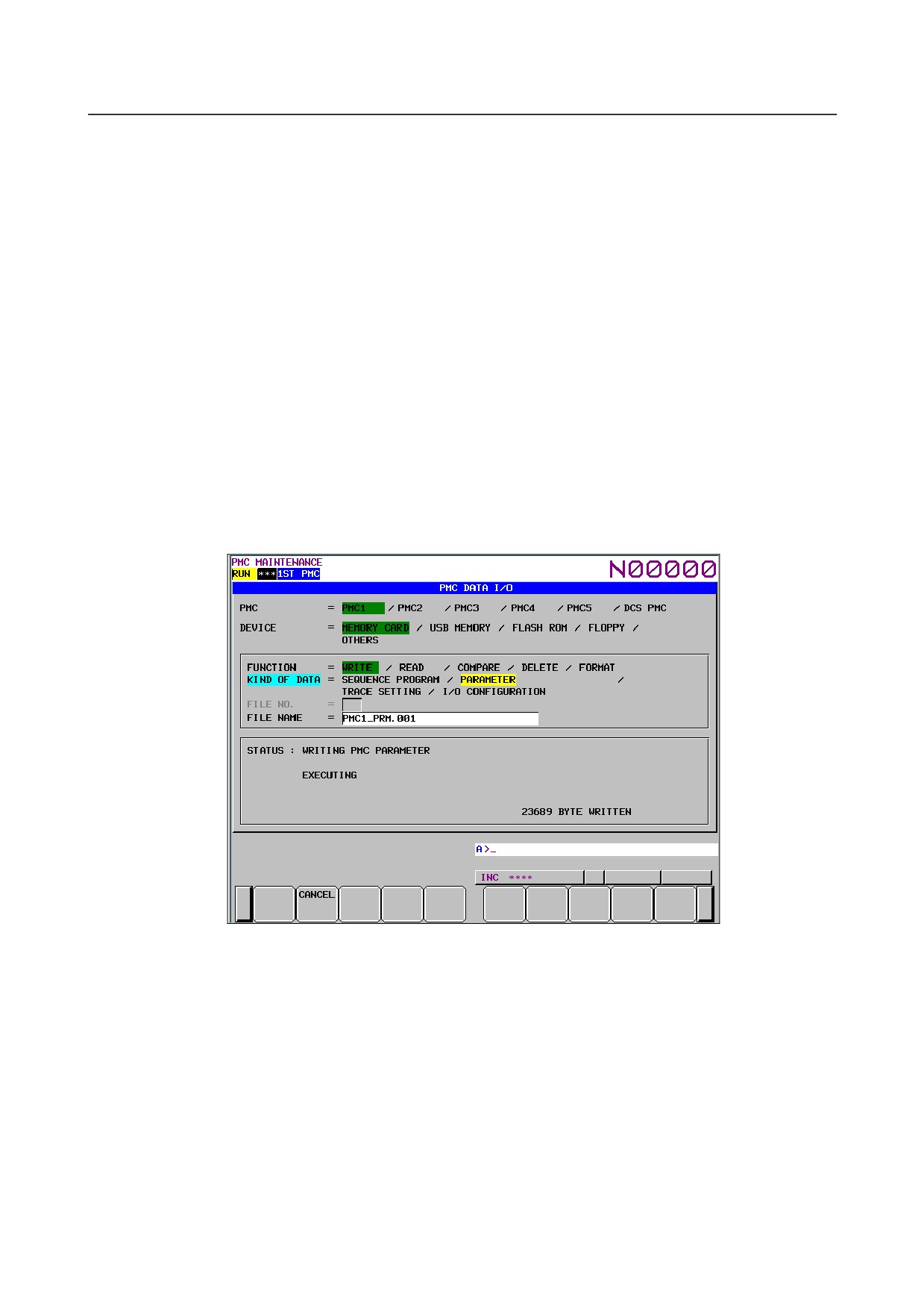
Fig. 6.5.7 (a) I/O screen
- 367 -
6.INTERFACE BETWEEN CNC AND PMC
B-64485EN/01
On this screen, sequence programs, PMC parameters, PMC message data for multi-language display,
trace setting data and I/O configuration data can be written to the specified device, read from the device,
and compared. The query selection cursor, which moves vertically from one question to another, is
displayed, as is the option selection cursor, which moves horizontally from one option to another.
The following types of devices can be used for input/output. The desired device type can be selected by
positioning the query selection cursor to "DEVICE" and moving the option selection cursor to that type.
• MEMORY CARD: Data can be output to and input from a memory card.
• USB MEMORY: Data can be output to and input from a USB memory.
• FLASH ROM:
Data can be output to and input from flash ROM.
• FLOPPY:
Data can be output to and input from handy files or floppy cassettes.
• OTHERS:
Data can be output to and input from other general-purpose RS-232C
input/output devices.
The multi-path PMC system enables an I/O target PMC to be selected. In STATUS in the lower part of
the screen, a detailed explanation of execution and the execution status are displayed. During write, read,
and comparison, the size of the data already transferred is indicated as the execution (intermediate) result.
The Fig. 6.5.7 (b) gives a display example shown when PMC parameters are written to a memory card:
Fig. 6.5.7 (c) I/O screen
- 368 -
B-64485EN/01
6.INTERFACE BETWEEN CNC AND PMC
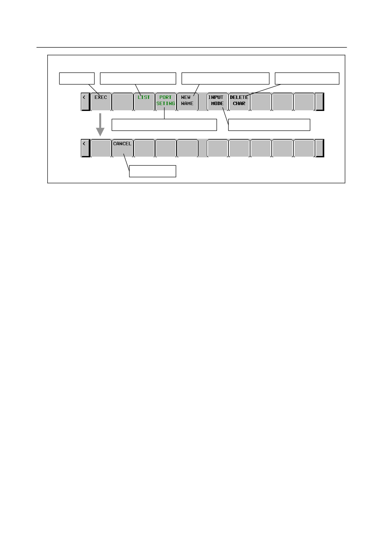
Soft keys on the I/O screen
Execution
Switch to the list screen
Generating a new file name
Delete a character
Switch to the port setting screen
Change the input mode
Cancellation
- 369 -
6.INTERFACE BETWEEN CNC AND PMC
B-64485EN/01
6.5.8
Displaying i/o devices connection status ([I/O DEVICE]
screen)
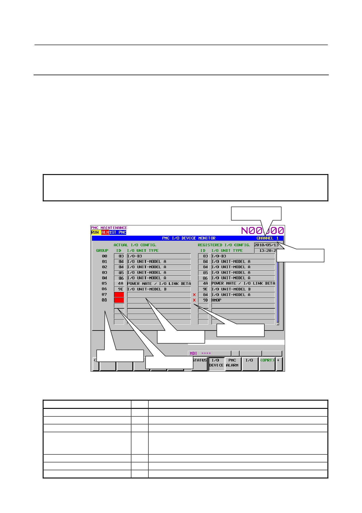
I/O DEVICE MONITOR screen shows the types and the ID codes of I/O Units that are connected to I/O
Link in order of Group number.
If the number of groups assigned in the I/O module assignment data does not match the number of
actually connected groups, the difference is displayed on the screen.
When the I/O device configuration is registered in this screen, the difference between the registered
groups and actually connected groups is displayed.
To switch the screen display to the I/O DEVICE MONITOR screen, press the [I/O DEVICE] soft key.
The screen supports the following operations.
• Registration of I/O device configuration
[REG.]
• Deletion of I/O device configuration
[DELETE]
NOTE
The [REG.] and [DELETE] operations are performed for each channel
separately.
Channel number
Registered date
Difference mark
I/O Unit type
Group number
I/O Unit ID code
図6.5.8 (a) I/O device screen
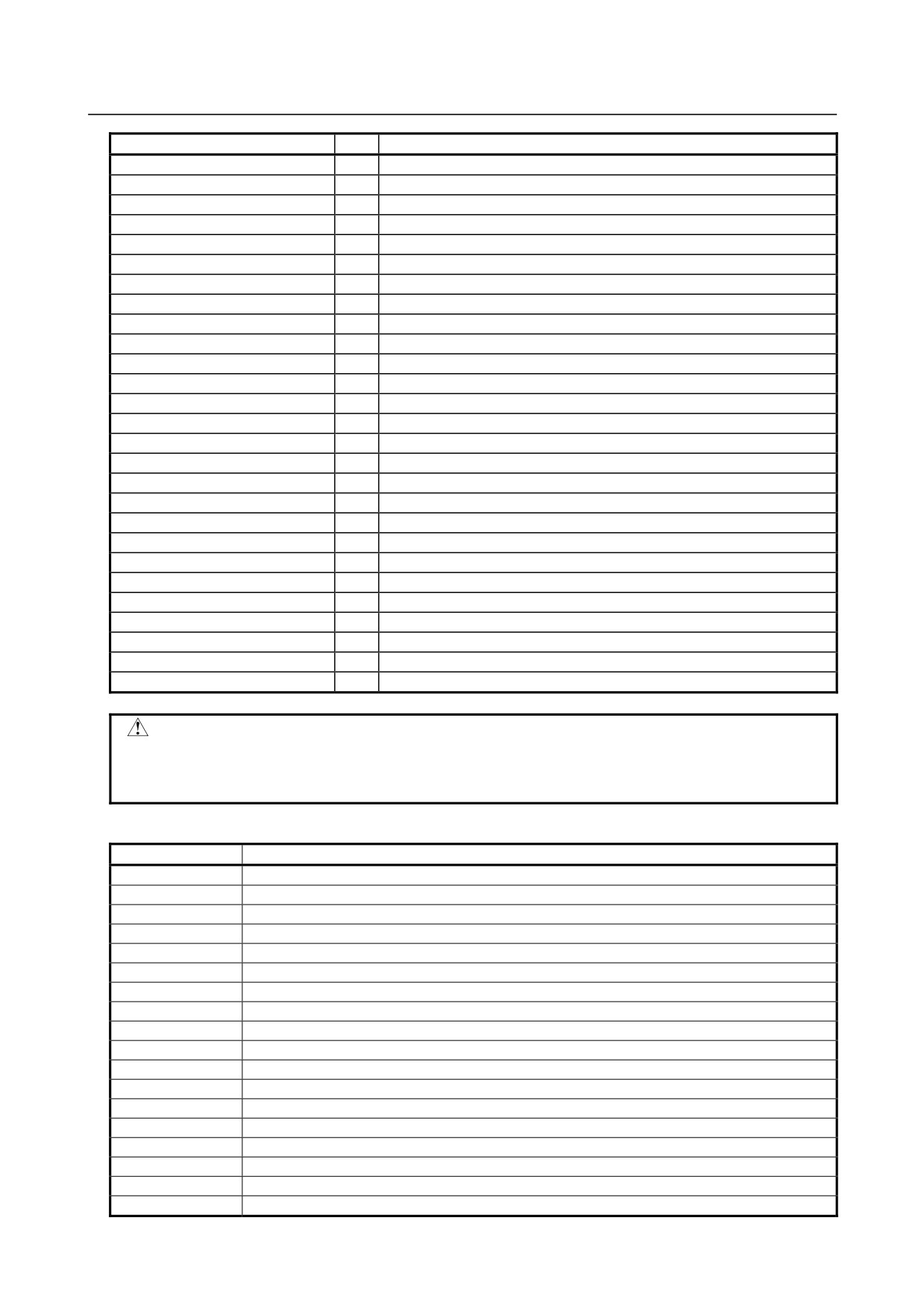
Table 6.5.8(a) Displayed type and actual type of I/O Units (for I/O Link)
Displayed I/O Unit
ID
Actual I/O Unit
CONNECTION UNIT
80
Connection Unit
OPERATOR PANEL
82
Connection Unit for Operators Panel
I/O-B3
83
I/O B3
IO UNIT-MODEL A
84
I/O Unit-MODEL A
86
87
POWER MATE / I/O LINK BETA
4A
Power Mate or I/O Link Beta
SERIES 0
50
Series 0
OPERATOR I/F BOARD (MPG1)
53
Machine Operators Panel Interface
- 370 -
B-64485EN/01
6.INTERFACE BETWEEN CNC AND PMC
Displayed I/O Unit
ID
Actual I/O Unit
LINK CONNECTION UNIT
96
I/O Link Connecting Unit
I/O UNIT-MODEL B
9E
I/O Unit-MODEL B
R-J MATE
61
R-J Mate
CONNECTOR PANEL MODULE
A9
I/O module for connector panel
OPERATOR PANEL A1
AA
I/O module for operator's panel
OPERATOR I/F BOARD (MPG3)
6B
Operator Interface (with MPG)
LOADER I/O
AF
I/O Board for Loader
FRC DIF
B0
DIF Board for ROBOCUT
FRC MIF
B1
MIF Board for ROBOCUT
I/O CARD
B2
I/O board
ROBOSHOT I/O CARD A
B3
I/O for ROBOSHOT
LOADER I/O (MATRIX)
B4
I/O Board for Loader (Matrix)
PROCESS I/O FA
B5
Process I/O for robot controller
PROCESS IO
89
Process I/O for robot controller
I/O LINK ADAPTER
8B
I/O Link adapter
ROBOT CONTROLLER
52
Controller for robot
OPERATOR PANEL
95
I/O for Series 0
LASER OSCILLATOR
97
Laser Oscillator
FIXED I/O TYPE A
98
I/O for Robot Type A
FIXED I/O TYPE B
99
I/O for Robot Type B
AS-I CONVERTER
77
AS-i Converter
OPERATOR PANEL B
A8
I/O Module (for Operator Panel 48/32)
MACHINE OPERATOR PANEL A
A8
I/O Module (for Machine Operator Panel of 0 Type)
CONNECTION UNIT C1 (MPG)
A8
Connection Unit C1 (with MPG)
MACHINE OPERATOR PANEL B
A8
I/O Module (for Machine Operator Panel)
I/O MODULE WITH LCD
A8
LCD display embedded I/O
UNKNOWN UNIT
-
Unknown I/O Unit
CAUTION
1 IDs other than those for the I/O units listed in Table 6.5.8(a) represent undefined
units.
2 I/O Units not for this CNC system are also written in Table 6.5.8(a).
Table 6.5.8 (b) Displayed type of I/O Units (for I/O Link i)
ID
Displayed I/O Unit
01
OP. PANEL (CABINET) I/O B
04
MACHINE OPERATORS PANEL
08
PANEL i AUTOMOTIVE SOFTKEY
0A
I/O MODULE TYPE-2
0B
I/O UNIT FOR 0i
14
I/O BOARD SLAVE0
15
I/O BOARD SLAVE1
17
TERMINAL I/O MODULE
1E
OPERATORS PANEL
53
OPERATORS PANEL I/F BOARD
6B
OPERATORS PANEL I/F BOARD
77
I/O LINK ASI CONVERTER
96
CONNECTION UNIT
A9
I/O FOR CONNECTOR PANEL
AA
I/O FOR OPERATORS PANEL A
AB
MULTISENSOR UNIT
B8
LASER OSCILLATOR
C6
I/O FOR OP. PANEL (DCS)
- 371 -