FANUC Series Series 16i-TB, Series 18i-TB, Series 160i-TB, Series 180i-TB. OPERATOR’S MANUAL - page 2
II. PROGRAMMING
B-63524EN/01
PROGRAMMING
1. GENERAL
GENERAL
1
11
1. GENERAL
PROGRAMMING
B-63524EN/01
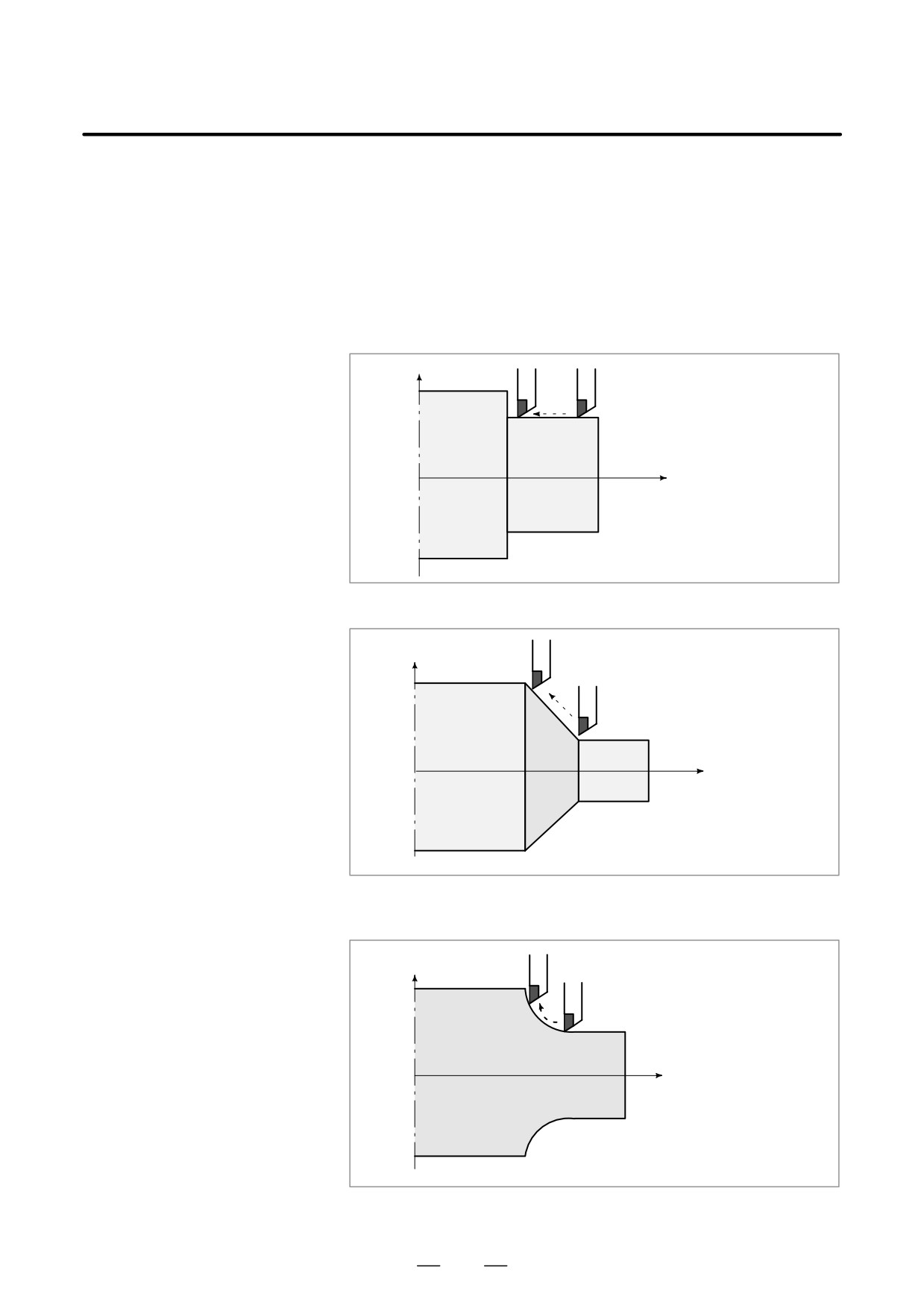
The tool moves along straight lines and arcs constituting the workpiece
1.1
parts figure (See II-4).
TOOL MOVEMENT
ALONG WORKPIECE
PARTS FIGURE-
INTERPOLATION
Explanations
D Tool movement along a
straight line
X
Tool
Program
G01 Z...;
Workpiece
Z
Fig.1.1 (a) Tool movement along the straight line which is parallel to Z-axis
X
Program
Tool
G01 X ... Z... ;
Workpiece
Z
Fig.1.1 (b) Tool movement along the taper line
D Tool movement along an
arc
X
Tool
Program
G02X ... Z ... R ... ;
or
G03X ... Z ... R ... ;
Workpiece
Z
Fig. 1.1 (c) Tool movement along an arc
12
B-63524EN/01
PROGRAMMING
1. GENERAL
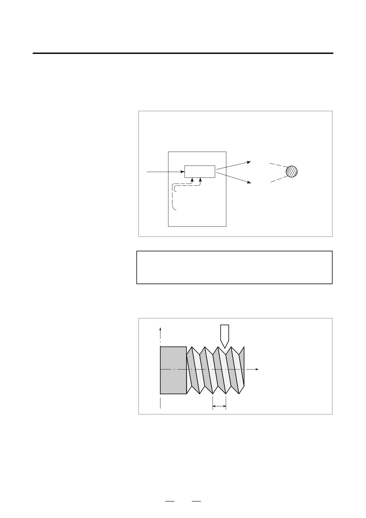
The term interpolation refers to an operation in which the tool moves
along a straight line or arc in the way described above.
Symbols of the programmed commands G01, G02, ... are called the
preparatory function and specify the type of interpolation conducted in
the control unit.
(a) Movement along straight line
(b) Movement along arc
G01 Z__;
G03X--Z--;
X--Z----;
Control unit
X axis
Tool
Interpolation
movement
Y axis
a) Movement
along straight
line
b) Movement
along arc
Fig. 1.1 (d) Interpolation function
NOTE
Some machines move tables instead of tools but this
manual assumes that tools are moved against workpieces.
D Thread cutting
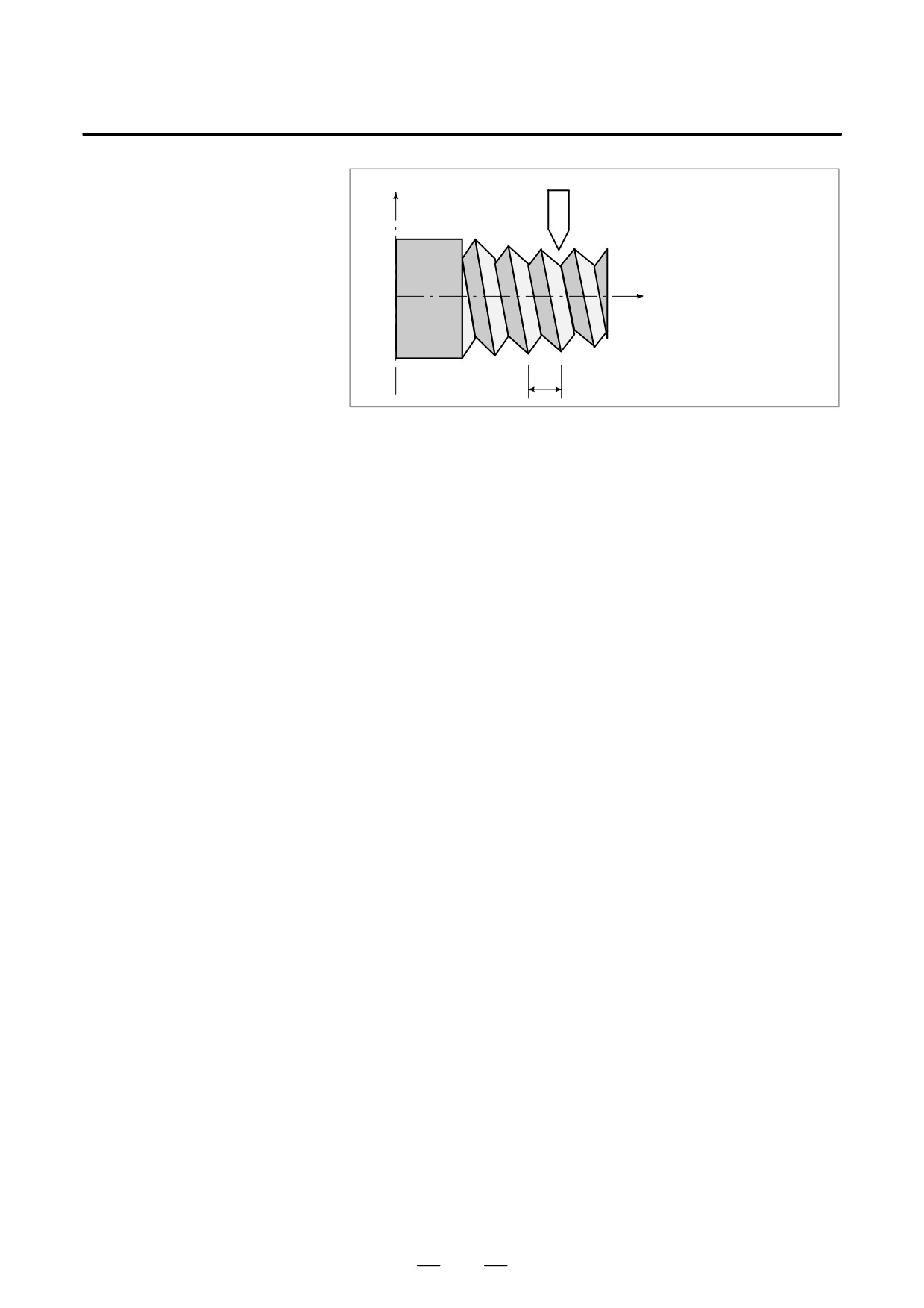
Threads can be cut by moving the tool in synchronization with spindle
rotation. In a program, specify the thread cutting function by G32.
X
Tool
Program
G32Z--F--;
Workpiece
Z
F
Fig. 1.1 (e) Straight thread cutting
13
1. GENERAL
PROGRAMMING
B-63524EN/01
X
Tool
Program
G32X--Z--F--;
Workpiece
Z
F
Fig. 1.1 (f) Taper thread cutting
14
B-63524EN/01
PROGRAMMING
1. GENERAL
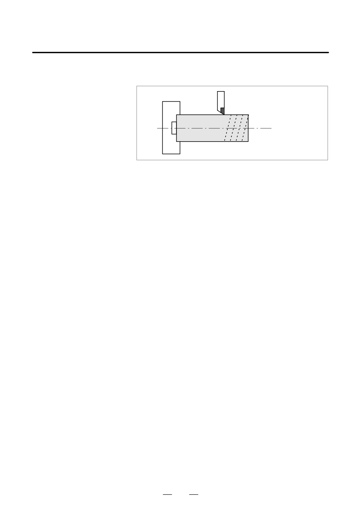
Movement of the tool at a specified speed for cutting a workpiece is called
1.2
the feed.
FEED-
FEED FUNCTION
Chuck
Tool
Workpiece
Fig. 1.2 (a) Feed function
Feedrates can be specified by using actual numerics.
For example, the following command can be used to feed the tool 2 mm
while the workpiece makes one turn :
F2.0
The function of deciding the feed rate is called the feed function (See
II-5).
15
1. GENERAL
PROGRAMMING
B-63524EN/01
1.3
PART DRAWING AND
TOOL MOVEMENT
1.3.1
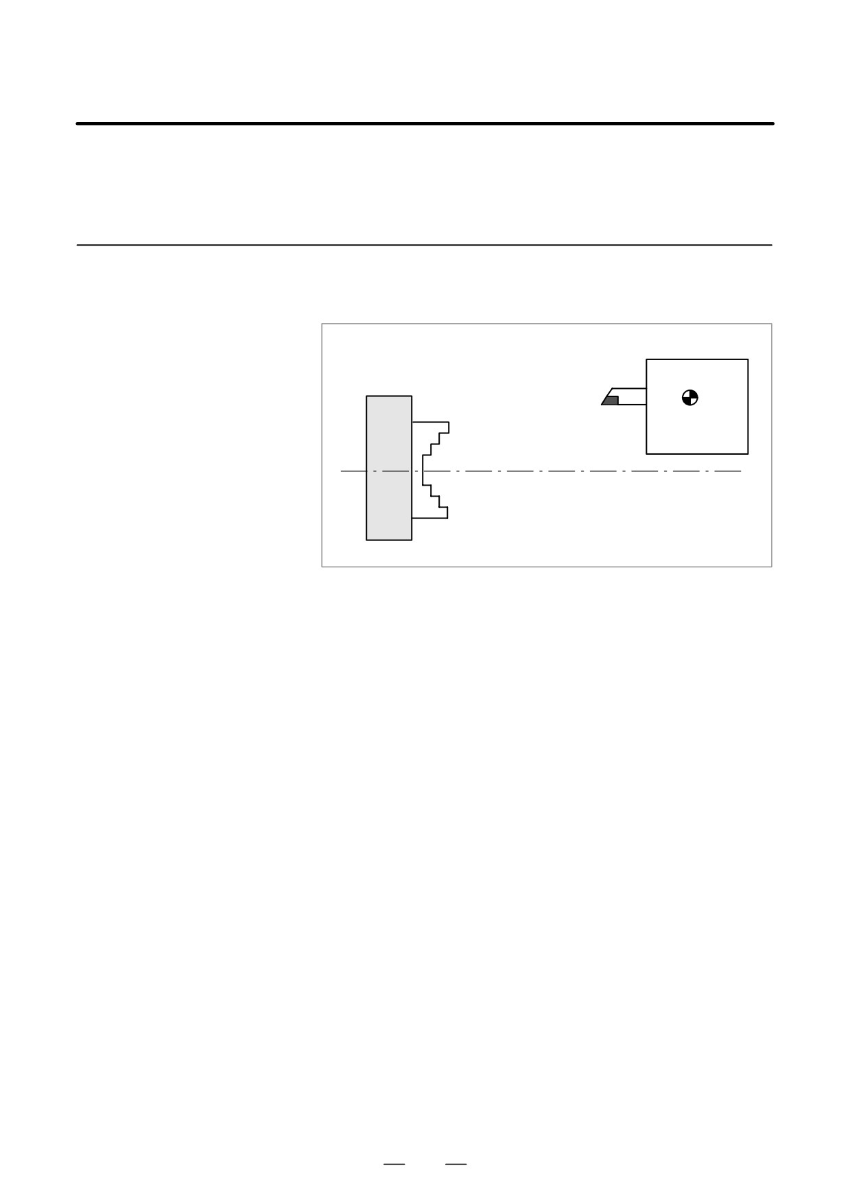
A CNC machine tool is provided with a fixed position. Normally, tool
change and programming of absolute zero point as described later are
Reference Position
performed at this position. This position is called the reference position.
(Machine-Specific
Position)
Tool post
Chuck
Reference
position
Fig. 1.3.1 (a) Reference position
Explanations
The tool can be moved to the reference position in two ways:
1. Manual reference position return (See III-3.1)
Reference position return is performed by manual button operation.
2. Automatic reference position return (See II-6)
In general, manual reference position return is performed first after
the power is turned on. In order to move the tool to the reference
position for tool change thereafter, the function of automatic
reference position return is used.
16
B-63524EN/01
PROGRAMMING
1. GENERAL
1.3.2
Coordinate System on
Part Drawing and
X
X
Coordinate System
Specified by CNC -
Program
Coordinate System
Z
Z
Coordinate system
Part drawing
CNC
Command
X
Workpiece
Z
Machine tool
Fig. 1.3.2 (a) Coordinate system
Explanations
D Coordinate system
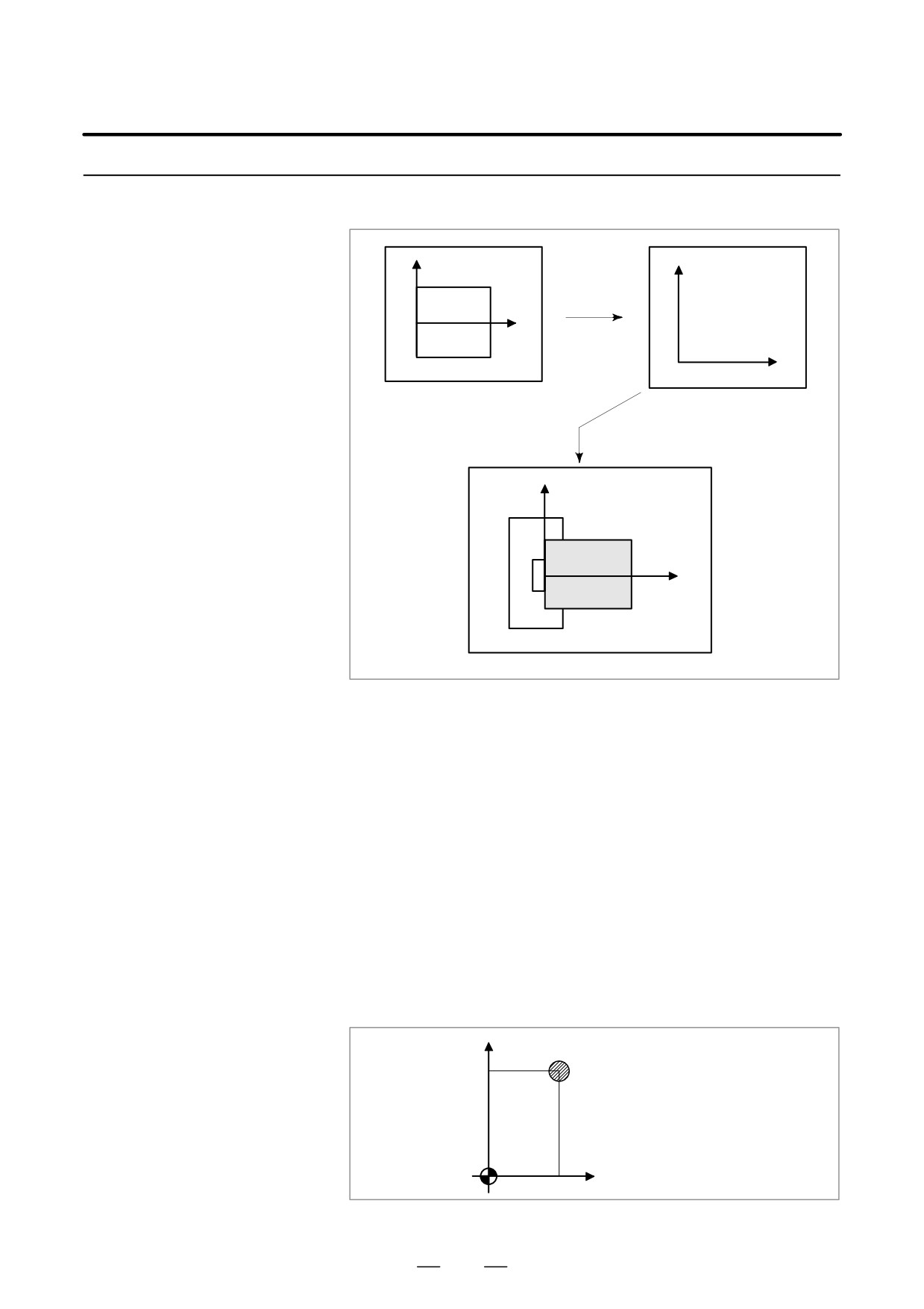
The following two coordinate systems are specified at different locations:
(See II-7)
1.
Coordinate system on part drawing
The coordinate system is written on the part drawing. As the program
data, the coordinate values on this coordinate system are used.
2.
Coordinate system specified by the CNC
The coordinate system is prepared on the actual machine tool. This
can be achieved by programming the distance from the current
position of the tool to the zero point of the coordinate system to be
set.
X
230
Present tool position
300
Distance to the zero point of a coor-
Program
dinate system to be set
zero point
Z
Fig. 1.3.2 (b) Coordinate system specified by the CNC
17
1. GENERAL
PROGRAMMING
B-63524EN/01
The tool moves on the coordinate system specified by the CNC in
accordance with the command program generated with respect to the
coordinate system on the part drawing, and cuts a workpiece into a shape
on the drawing.
Therefore, in order to correctly cut the workpiece as specified on the
drawing, the two coordinate systems must be set at the same position.
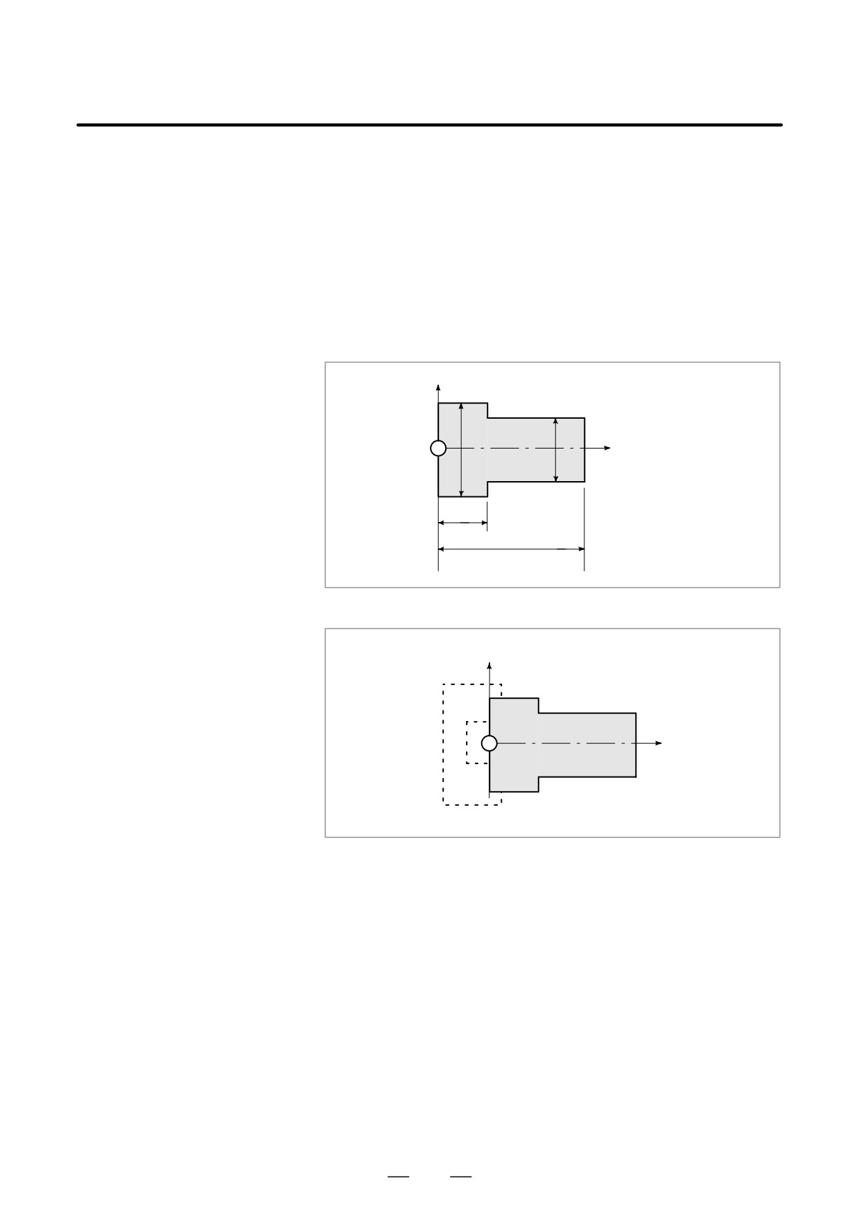
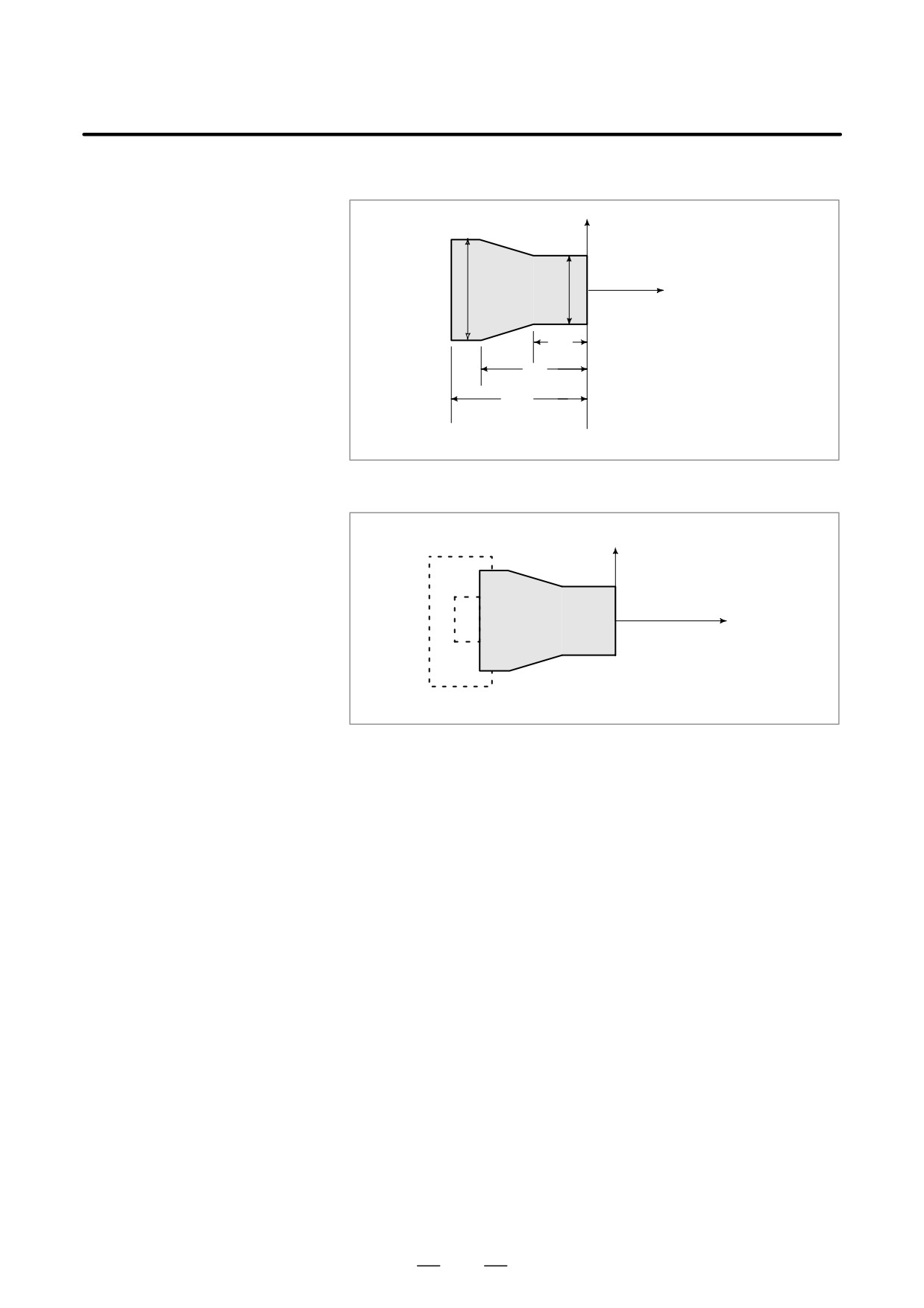
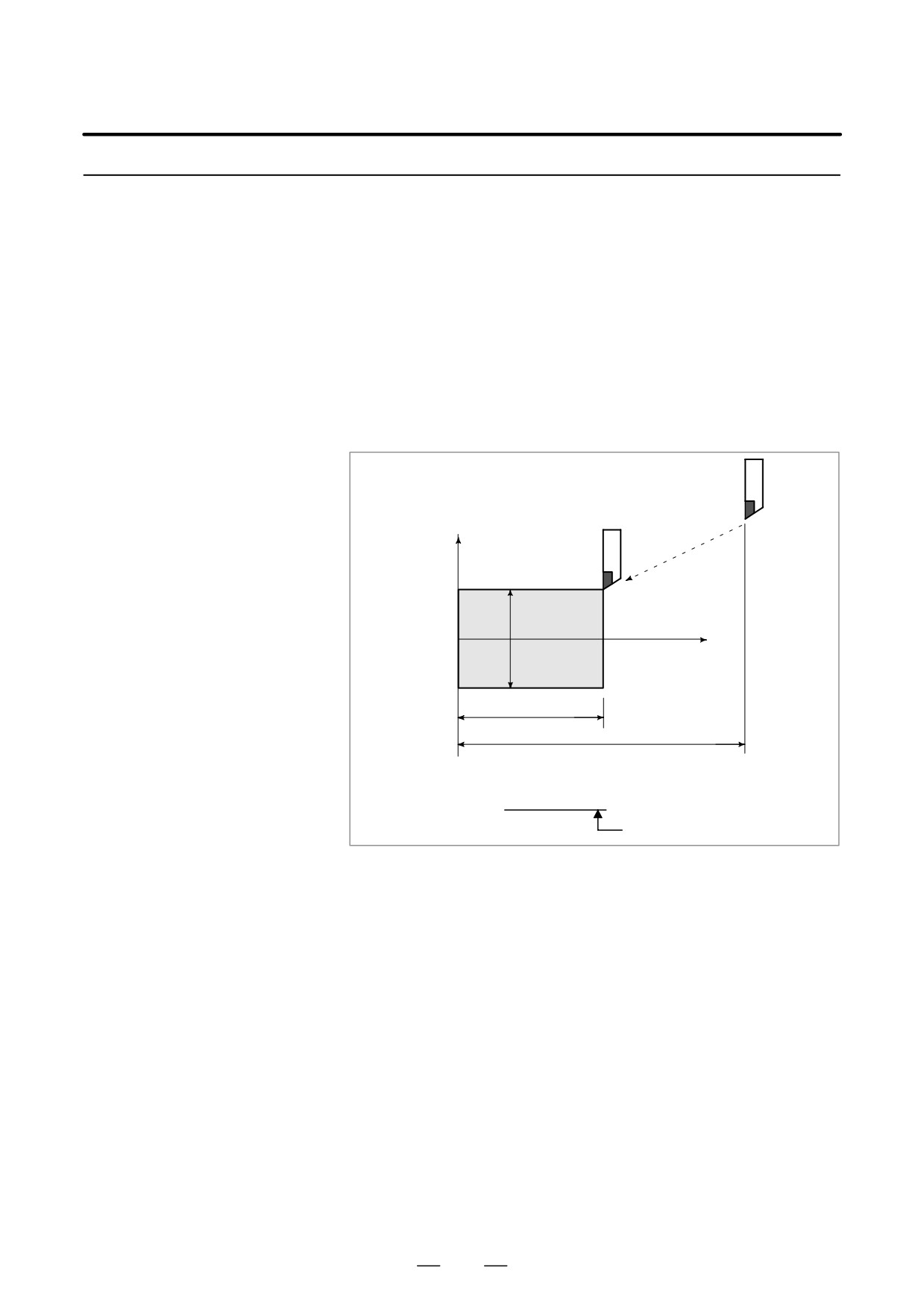
D Methods of setting the
The following method is usually used to define two coordinate systems
two coordinate systems
at the same location.
in the same position
1. When coordinate zero point is set at chuck face
X
Workpiece
Z
60
40
40
150
Fig. 1.3.2 (c) Coordinates and dimensions on part drawing
X
Workpiece
Z
Fig. 1.3.2 (d) Coordinate system on lathe as specified by CNC
(made to coincide with the coordinate system on part drawing)
18
B-63524EN/01
PROGRAMMING
1. GENERAL
2. When coordinate zero point is set at work end face.
X
Workpiece
60
30
Z
30
80
100
Fig. 1.3.2 (e) Coordinates and dimensions on part drawing
X
Workpiece
Z
Fig. 1.3.2 (f) Coordinate system on lathe as specified by CNC
(made to coincide with the coordinate system on part drawing)
19
1. GENERAL
PROGRAMMING
B-63524EN/01
1.3.3
How to Indicate
Command Dimensions
for Moving the Tool -
Absolute, Incremental
Commands
Explanations
Methods of command for moving the tool can be indicated by absolute
or incremental designation (See II-8.1).
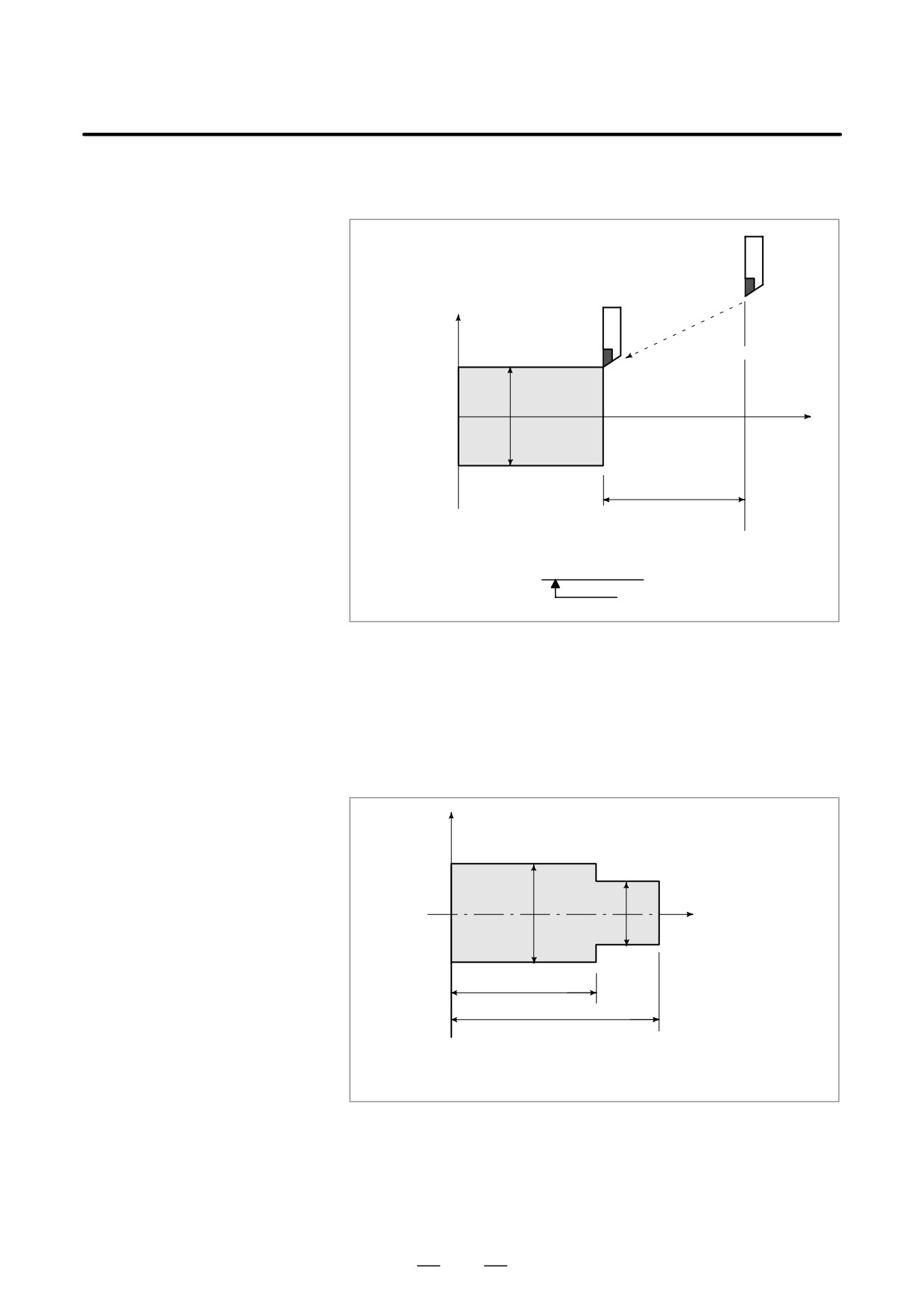
D Absolute command
The tool moves to a point at “the distance from zero point of the
coordinate system” that is to the position of the coordinate values.
Tool
X
A
B
Workpiece
Z
φ30
70
110
Command specifying movement from point A to point B
G90X30.0Z70.0;
Coordinates of point B
Fig. 1.3.3 (a) Absolute command
20
B-63524EN/01
PROGRAMMING
1. GENERAL
D Incremental command
Specify the distance from the previous tool position to the next tool
position.
Tool
A
X
φ60
B
Z
φ30
40
Command specifying movement from point A to point B
U-30.0W-40.0
Distance and direction for
movement along each axis
Fig. 1.3.3 (b) Incremental command
D Diameter programming /
Dimensions of the X axis can be set in diameter or in radius. Diameter
radius programming
programming or radius programming is employed independently in each
machine.
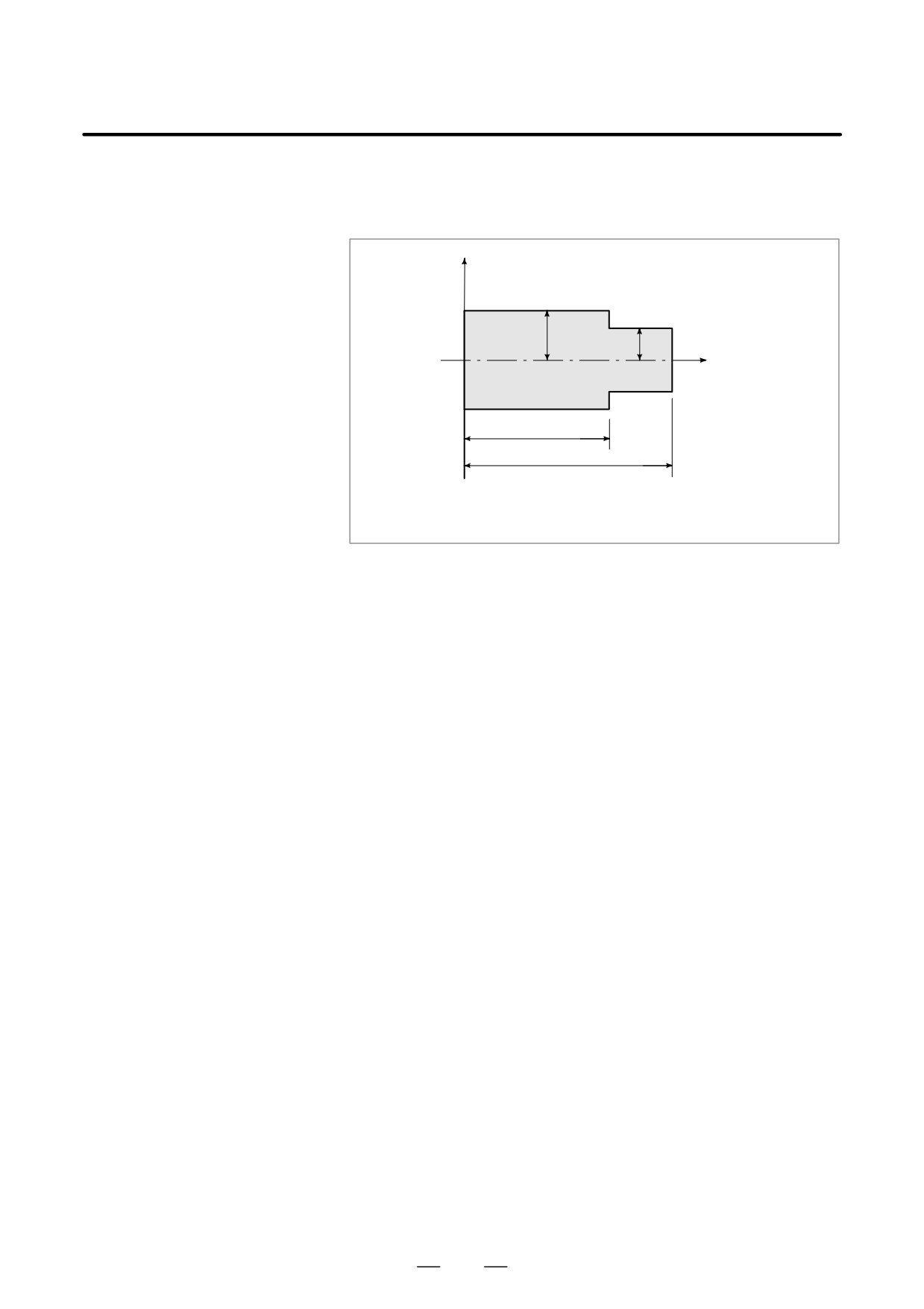
1. Diameter programming
In diameter programming, specify the diameter value indicated on the
drawing as the value of the X axis.
X
B
A
Workpiece
Z
φ40
φ30
60
80
Coordinate values of points A and B
A(30.0, 80.0), B(40.0, 60.0)
Fig. 1.3.3 (c) Diameter programming
21
1. GENERAL
PROGRAMMING
B-63524EN/01
2. Radius programming
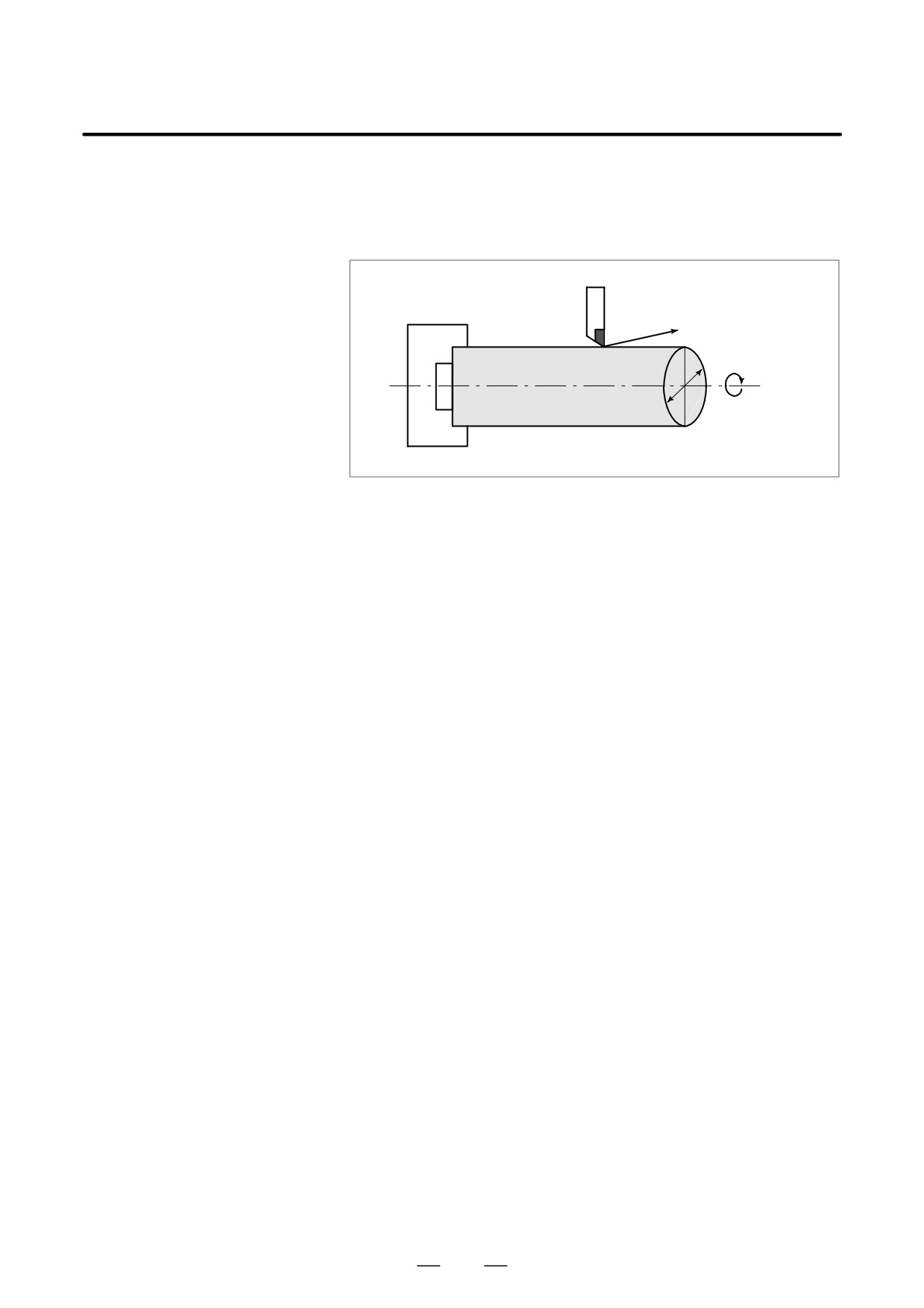
In radius programming, specify the distance from the center of the
workpiece, i.e. the radius value as the value of the X axis.
X
B
A
20
15
Workpiece
Z
60
80
Coordinate values of points A and B
A(15.0, 80.0), B(20.0, 60.0)
Fig. 1.3.3 (d) Radius programming
22
B-63524EN/01
PROGRAMMING
1. GENERAL
The speed of the tool with respect to the workpiece when the workpiece
1.4
is cut is called the cutting speed.
CUTTING SPEED -
As for the CNC, the cutting speed can be specified by the spindle speed
SPINDLE SPEED
in min-1 unit.
FUNCTION
Tool
V: Cutting speed
v m/min
φD
N min-1
Workpiece
Fig. 1.4 Cutting speed
Examples
<When a workpiece 200 mm in diameter should be machined at
a cutting speed of 300 m/min. >
The spindle speed is approximately 478 min-1, which is obtained from
N=1000v/πD. Hence the following command is required:
S478 ;
Commands related to the spindle speed are called the spindle speed
function (See II-9).
The cutting speed v (m/min) can also be specified directly by the speed
value. Even when the workpiece diameter is changed, the CNC changes
the spindle speed so that the cutting speed remains constant.
This function is called the constant surface speed control function
(See II-9.3).
23

1. GENERAL
PROGRAMMING
B-63524EN/01
When drilling, tapping, boring, milling or the like, is performed, it is
1.5
necessary to select a suitable tool. When a number is assigned to each tool
SELECTION OF
and the number is specified in the program, the corresponding tool is
TOOL USED FOR
selected.
VARIOUS
MACHINING - TOOL
FUNCTION
Tool number
01
06
02
05
Tool post
03
04
Fig. 1.5 Tool used for various machining
Examples
<When No.01 is assigned to a roughing tool>
When the tool is stored at location 01 of the tool post, the tool can be
selected by specifying T0101.
This is called the tool function (See II-10).
24
B-63524EN/01
PROGRAMMING
1. GENERAL
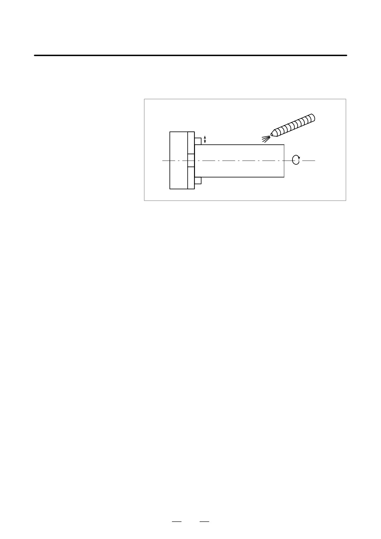
When machining is actually started, it is necessary to rotate the spindle,
1.6
and feed coolant. For this purpose, on-off operations of spindle motor and
COMMAND FOR
coolant valve should be controlled (See II-11).
MACHINE
OPERATIONS -
Coolant on/off
MISCELLANEOUS
FUNCTION
Chuck open/close
CW spindle rotation
Workpiece
Fig. 1.6 Command for machine operations
The function of specifying the on-off operations of the components of the
machine is called the miscellaneous function. In general, the function is
specified by an M code.
For example, when M03 is specified, the spindle is rotated clockwise at
the specified spindle speed.
25
1. GENERAL
PROGRAMMING
B-63524EN/01
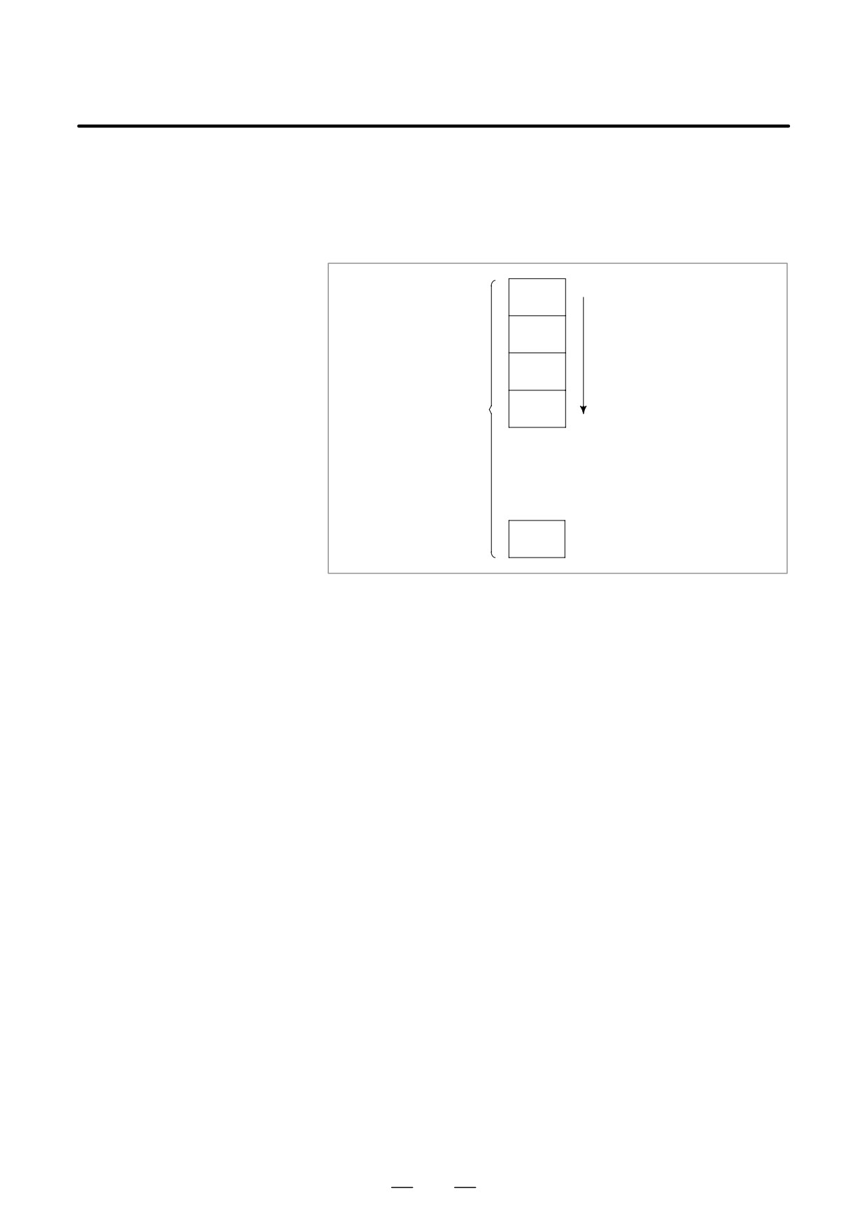
A group of commands given to the CNC for operating the machine is
1.7
called the program. By specifying the commands, the tool is moved along
PROGRAM
a straight line or an arc, or the spindle motor is turned on and off.
CONFIGURATION
In the program, specify the commands in the sequence of actual tool
movements.
Block
Block
Tool movement sequence
Block
Program
Block
⋅
⋅
⋅
⋅
Block
Fig. 1.7 (a) Program configuration
A group of commands at each step of the sequence is called the block.
The program consists of a group of blocks for a series of machining. The
number for discriminating each block is called the sequence number, and
the number for discriminating each program is called the program number
(See II-12).
26
B-63524EN/01
PROGRAMMING
1. GENERAL
Explanations
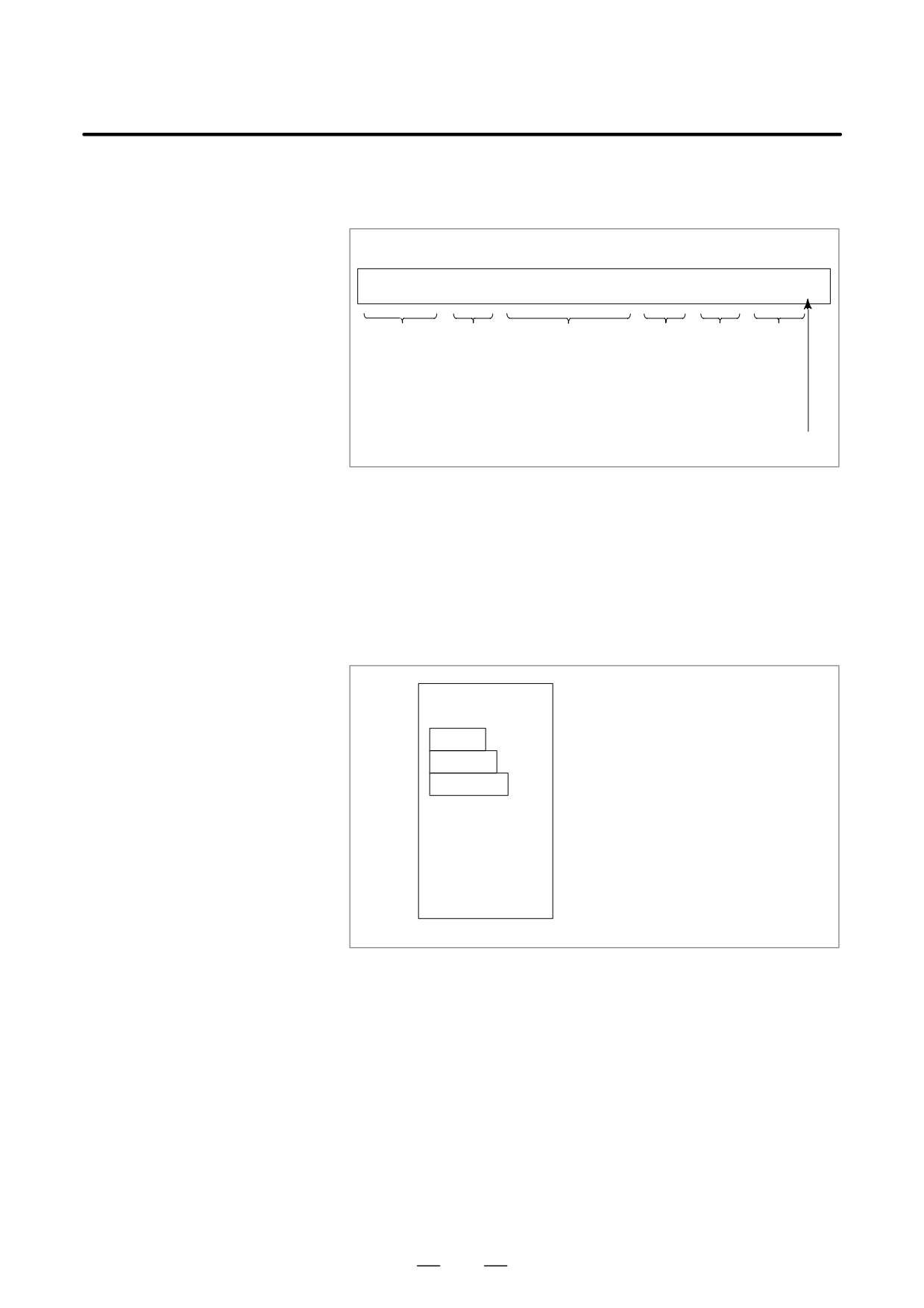
The block and the program have the following configurations.
D Block
1 block
N fffff G ff Xff.f Zfff.f M ff S ff T ff ;
Sequence Preparatory Dimension word Miscel-
Spindle Tool
number
function
laneous
function func-
function
tion
End of
block
Fig. 1.7 (b) Block configuration
A block begins with a sequence number that identifies that block and ends
with an end-of-block code.
This manual indicates the end-of-block code by ; (LF in the ISO code and
CR in the EIA code).
The contents of the dimension word depend on the preparatory function.
In this manual, the portion of the dimension word may be represent as IP_.
D Program
;
Offff;
Program number
Block
Block
Block
⋅
⋅
⋅
⋅
⋅
⋅
M30 ;
End of program
Fig. 1.7 (c) Program configuration
Normally, a program number is specified after the end-of-block (;) code
at the beginning of the program, and a program end code (M02 or M30)
is specified at the end of the program.
27
1. GENERAL
PROGRAMMING
B-63524EN/01
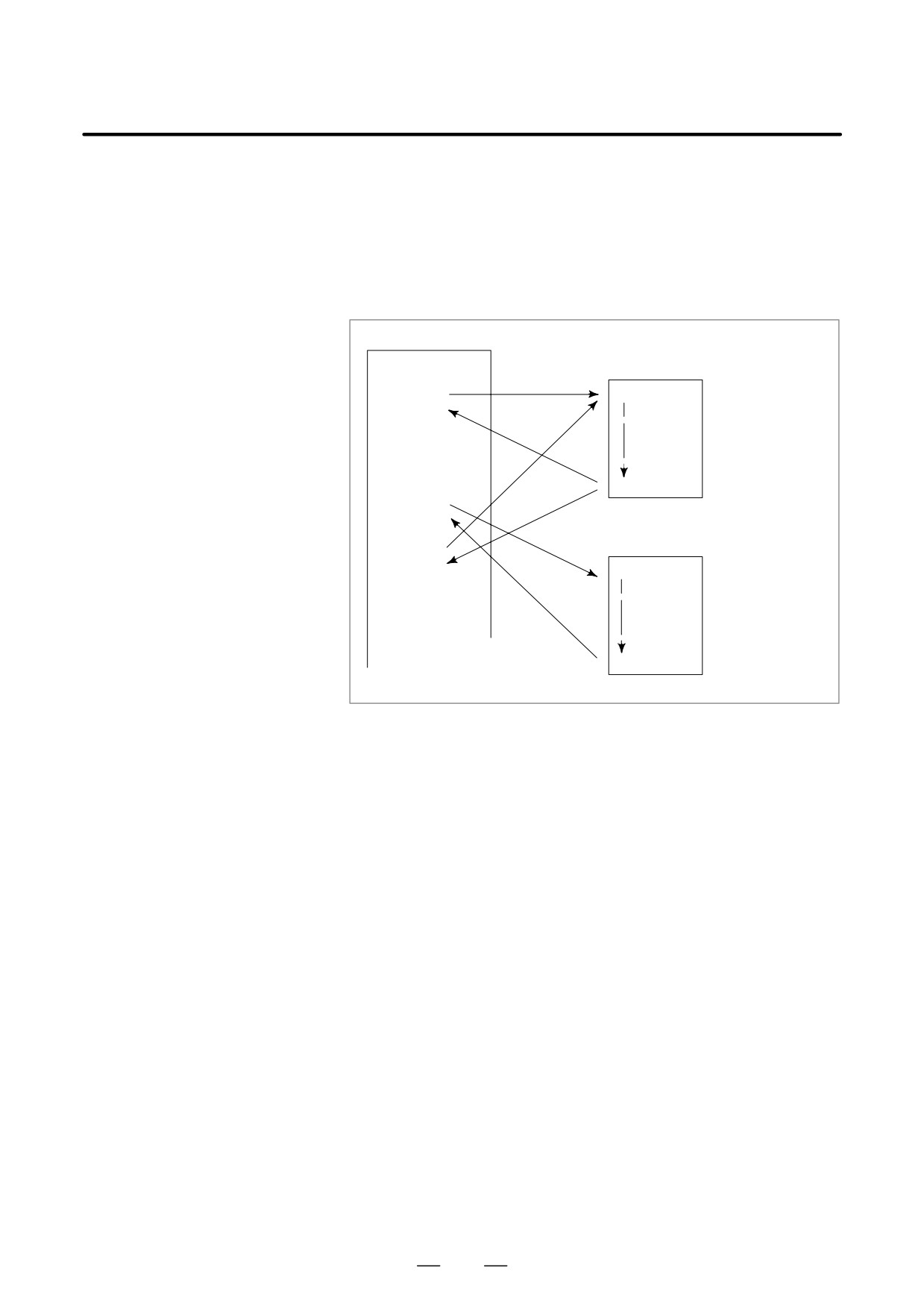
D Main program and
When machining of the same pattern appears at many portions of a
subprogram
program, a program for the pattern is created. This is called the
subprogram. On the other hand, the original program is called the main
program. When a subprogram execution command appears during
execution of the main program, commands of the subprogram are
executed. When execution of the subprogram is finished, the sequence
returns to the main program.
Main program
⋅
Subprogram #1
⋅
M98P1001
O1001
Program for
hole #1
⋅
⋅
⋅
M99
M98P1002
⋅
⋅
Subprogram #2
O1002
Program for
M
⋅
hole #2
⋅
⋅
⋅
M99
28
B-63524EN/01
PROGRAMMING
1. GENERAL
1.8
TOOL FIGURE AND
TOOL MOTION BY
PROGRAM
Explanations
D Machining using the end
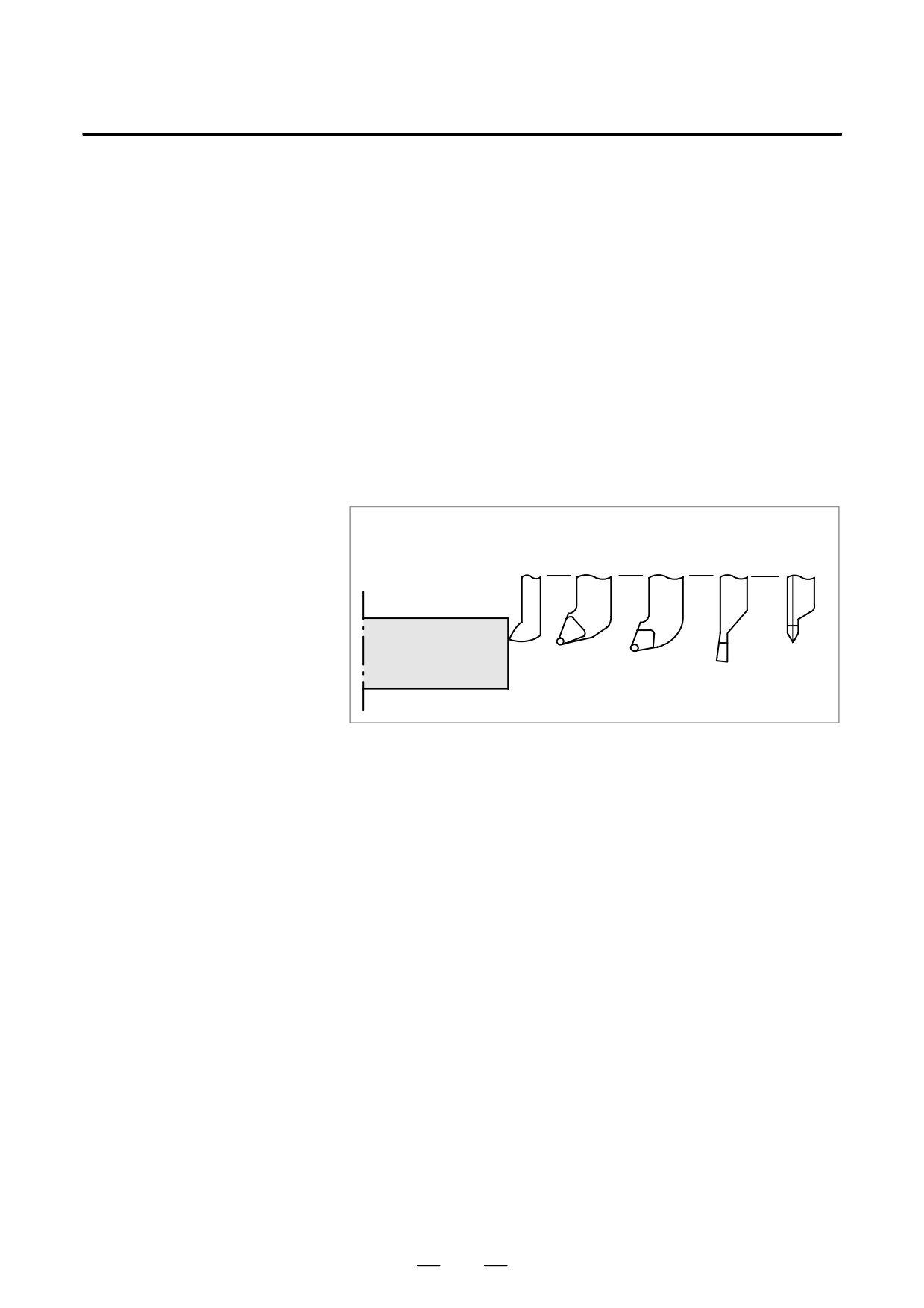
Usually, several tools are used for machining one workpiece. The tools
of cutter - Tool length
have different tool length. It is very troublesome to change the program
compensation function
in accordance with the tools.
(See II-15.1)
Therefore, the length of each tool used should be measured in advance.
By setting the difference between the length of the standard tool and the
length of each tool in the CNC (data display and setting : see III-11),
machining can be performed without altering the program even when the
tool is changed. This function is called tool length compensation.
Rough
Thread
Standard
Finishing Grooving
cutting
cutting
tool
tool
tool
tool
tool
Workpiece
Fig. 1.8 Tool offset
29
1. GENERAL
PROGRAMMING
B-63524EN/01
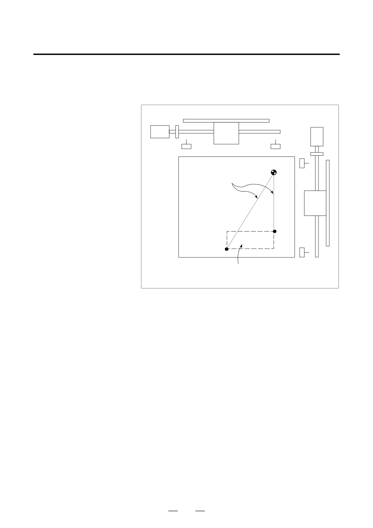
Limit switches are installed at the ends of each axis on the machine to
1.9
prevent tools from moving beyond the ends. The range in which tools can
TOOL MOVEMENT
move is called the stroke. Besides the stroke limits, data in memory can
RANGE - STROKE
be used to define an area which tools cannot enter.
Table
Motor
Limit switch
Machine zero point
Specify these distances.
ÇÇÇÇÇÇ
ÇÇÇÇÇÇ
Tools cannot enter this area. The area is specified by data in memory or
a program.
Besides strokes defined with limit switches, the operator can define an
area which the tool cannot enter using a program or data in memory. This
function is called stroke check (See III-6.3).
30
B-63524EN/01
PROGRAMMING
2. CONTROLLED AXES
CONTROLLED AXES
2
31
2. CONTROLLED AXES
PROGRAMMING
B-63524EN/01
2.1
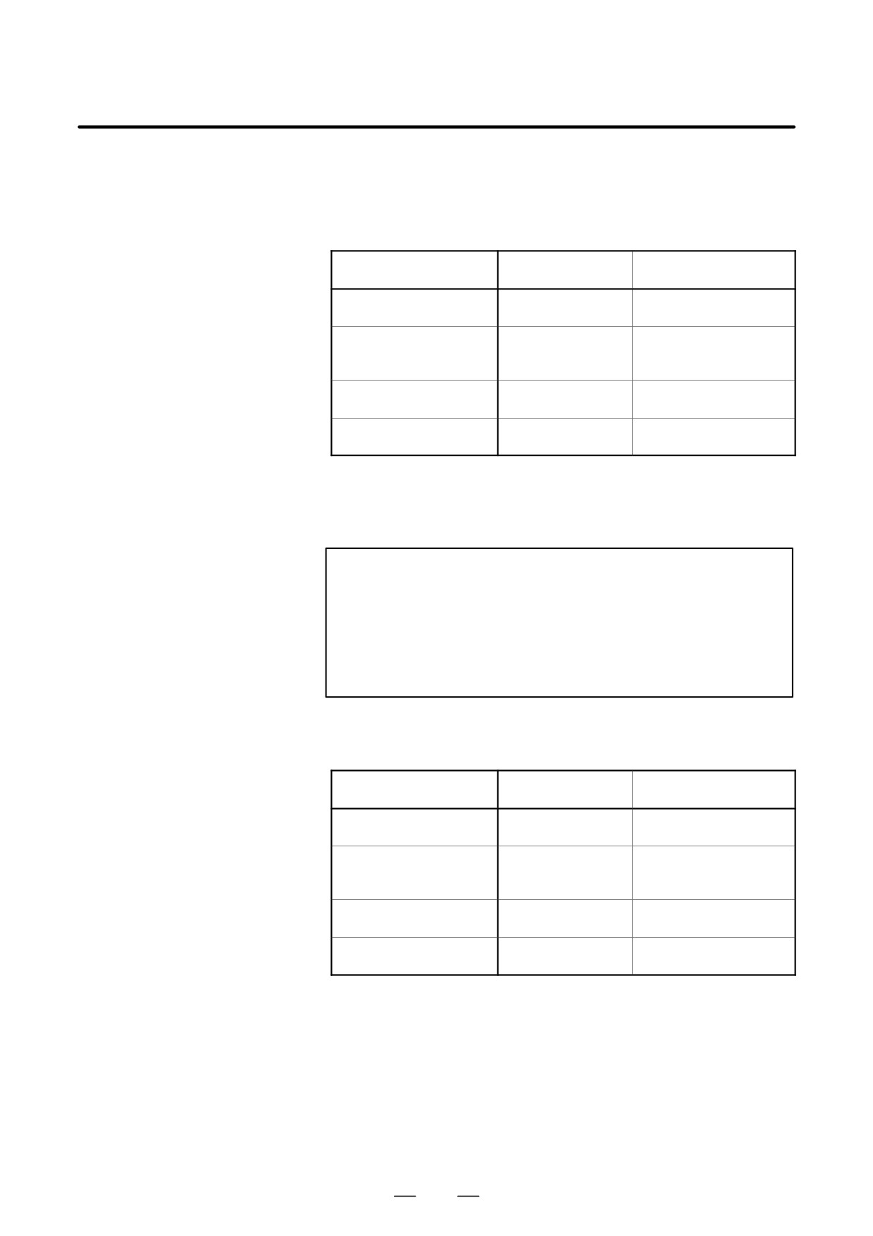
CONTROLLED AXES
Series 16i
Series 160i
16i-TB
16i-TB, 160i-TB
Item
160i-TB
(two-path control)
Number of basic
2 axes
2 axes for each tool post
controlled axes
(4 axes in total)
Controlled axis expansion
Max. 8 axes
Max. 8 axes for each tool
(total)
(Included in Cs axis)
post (Included in Cs axis)
(Note)
Number of basic simulta-
2 axes
2 axes for each tool post
neously controlled axes
(4 axes in total)
Simultaneously controlled
Max. 6 axes
Max. 6 axes for each tool
axis expansion (total)
post
The table above lists the number of controlled axes of one-path control
and two-CPU two-path control. For the number of controlled axes of
one-CPU two-path control and two-CPU three-path control, refer to the
specifications.
NOTE
1
A two-path control system with the 7.2″/8.4″ LCD has up to
eight controlled axes.
2
The number of simultaneously controllable axes for manual
operation (jog feed, incremental feed, or manual handle
feed) is 1 or 3 (1 when bit 0 (JAX) of parameter 1002 is set
to 0 and 3 when it is set to 1).
Series 18i
Series 180i
18i-TB
18i-TB, 180i-TB
Item
180i-TB
(two-path control)
Number of basic
2 axes
2 axes for each tool post
controlled axes
(4 axes in total)
Controlled axis expansion
Max. 6 axes
Max. 6 axes for each tool
(total)
(Included in Cs axis)
post (Included in Cs axis)
(Note)
Number of basic simulta-
2 axes
2 axes for each tool post
neously controlled axes
(4 axes in total)
Simultaneously controlled
Max. 4 axes
Max. 4 axes for each tool
axis expansion (total)
post
The table above lists the number of controlled axes of one-path control
and two-CPU two-path control.
For the number of controlled axes of one-CPU two-path control, refer to
the specifications.
32
B-63524EN/01
PROGRAMMING
2. CONTROLLED AXES
NOTE
1
A two-path control system with the 7.2″/8.4″ LCD has up to
eight controlled axes.
2
The number of simultaneously controllable axes for manual
operation (jog feed, incremental feed, or manual handle
feed) is 1 or 3 (1 when bit 0 (JAX) of parameter 1002 is set
to 0 and 3 when it is set to 1).
33
2. CONTROLLED AXES
PROGRAMMING
B-63524EN/01
The names of two basic axes are always X and Z; the names of additional
2.2
axes can be optionally selected from A, B, C, U, V, W, and Y by using
NAMES OF AXES
parameter No.1020.
Each axis name is determined according to parameter No. 1020. If the
parameter specifies 0 or anything other than the nine letters, the axis name
defaults to a number from 1 to 8.
With two-path control, the names of two basic axes for one tool post are
always X and Z; the names of additional axes can be optionally selected
from A, B, C, U, V, W, and Y by using parameter No. 1020. For one tool
post, the same axis name cannot be assigned to multiple axes, but the same
axis name can be used with the other tool post.
Limitations
D Default axis name
When a default axis name (1 to 8) is used, the system cannot operate in
MEM, MDI, or RMT mode.
D Duplicate axis name
If the parameter specifies an axis name more than once, only the first axis
to be assigned that axis name becomes operable.
NOTE
1
When G code system A is used, the letters U, V, and W
cannot be used as an axis name (hence, the maximum of
six controlled axes), because these letters are used as
incremental commands for X, Y, and Z. To use the letters
U, V, and W as axis names, the G code system must be B
or C. Likewise, letter H is used as an incremental command
for C, thus incremental commands cannot be used if A or B
is used as an axis name.
2
With two-path control, when information
(such as the
current position) about each axis is displayed on the screen,
an axis name may be followed by a subscript to indicate a
tool post number (e.g., X1 and X2). This is axis name to help
the user to easily understand which tool post an axis
belongs to. When writing a program, the user must specify
X, Y, Z, U, V, W, A, B, and C without attaching a subscript.
3
In G76 (multiple-thread cutting), the A address in a block
specifies the tool nose angle instead of a command for axis
A.
If C or A is used as an axis name, C or A cannot be used as
an angle command for a straight line in chamfering or direct
drawing dimension programming. Therefore, C and A
should be used according to bit 4 (CCR) of parameter No.
3405.
34
B-63524EN/01
PROGRAMMING
2. CONTROLLED AXES
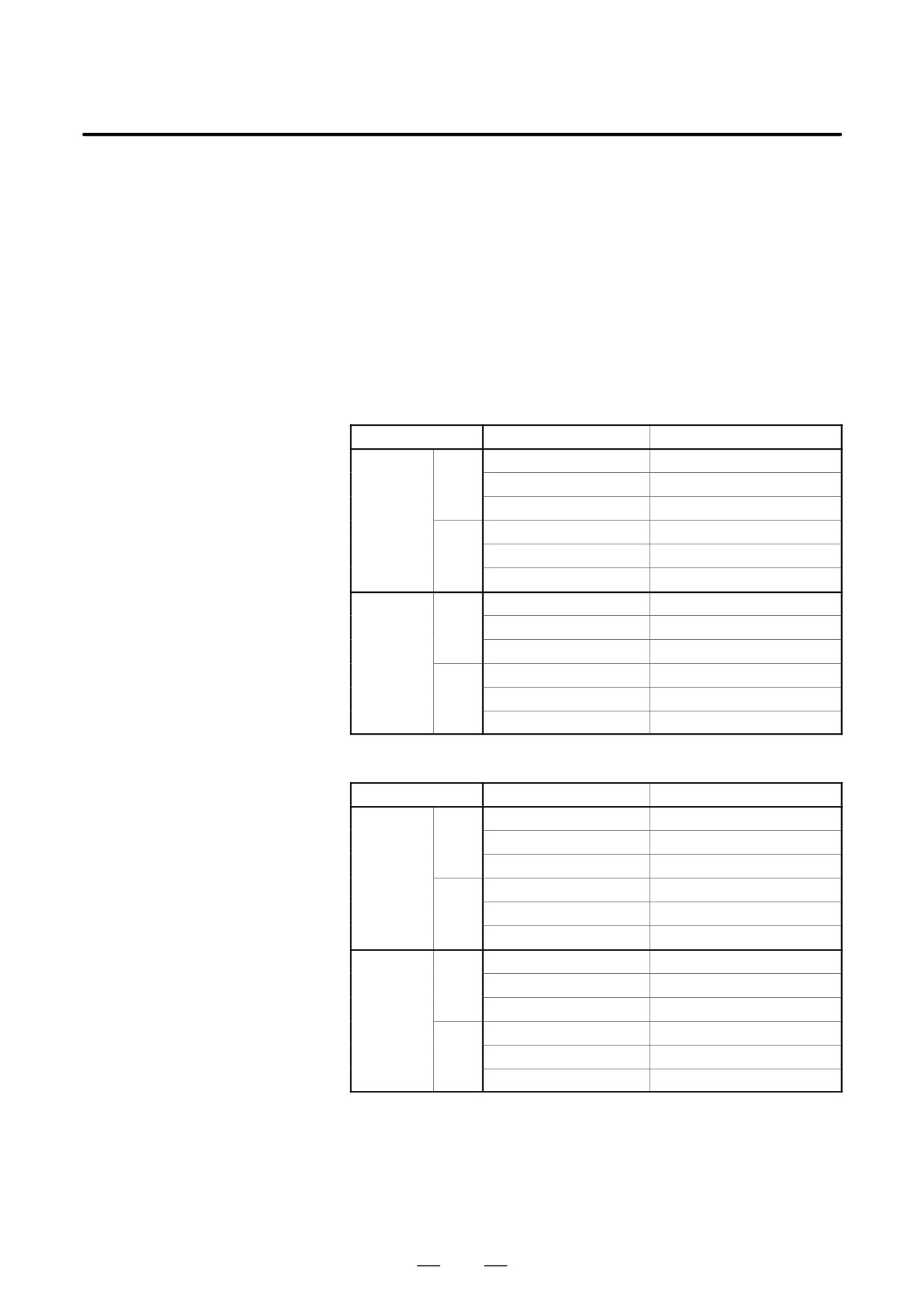
The increment system consists of the least input increment (for input ) and
2.3
least command increment (for output). The least input increment is the
INCREMENT SYSTEM
least increment for programming the travel distance. The least command
increment is the least increment for moving the tool on the machine. Both
increments are represented in mm, inches, or degrees.
The increment system is classified into IS-B and IS-C (Tables 2.3 (a) and
2.3 (b)). Select IS-B or IS-C using bit 1 (ISC) of parameter 1004. When
the IS-C increment system is selected, it is applied to all axes and the 1/10
increment system option is required. The setting of parameter ISC (No.
1004#4) is valid for all axes. When IS-C is selected, for example, the
setting units for all axes are IS-C.
Table 2.3 (a) Increment system IS-B
Least input increment
Least command increment
Metric
mm
0.001 mm (Diameter)
0.0005 mm
system
input
0.001 mm (Radius)
0.001 mm
machine
0.001 deg
0.001 deg
inch
0.0001 inch (Diameter)
0.0005 inch
input
0.0001 inch (Radius)
0.001 inch
0.001 deg
0.001 deg
Inch
mm
0.001 mm (Diameter)
0.00005 mm
machine
input
0.001 mm (Radius)
0.0001 mm
system
0.001 deg
0.001 deg
inch
0.0001 inch (Diameter)
0.00005 inch
input
0.0001 inch (Radius)
0.0001 inch
0.001 deg
0.001 deg
Table 2.3 (b) Increment system IS-C
Least input increment
Least command increment
Metric
mm
0.0001 mm (Diameter)
0.00005 mm
system
input
0.0001 mm (Radius)
0.0001 mm
machine
0.0001 deg
0.0001 deg
inch
0.00001 inch (Diameter)
0.00005 inch
input
0.00001 inch (Radius)
0.0001 inch
0.0001 deg
0.0001 deg
Inch
mm
0.0001 mm (Diameter)
0.000005 mm
machine
input
0.0001 mm (Radius)
0.00001 mm
system
0.0001 deg
0.0001 deg
inch
0.00001 inch (Diameter)
0.000005 inch
input
0.00001 inch (Radius)
0.00001 inch
0.0001 deg
0.0001 deg
35
2. CONTROLLED AXES
PROGRAMMING
B-63524EN/01
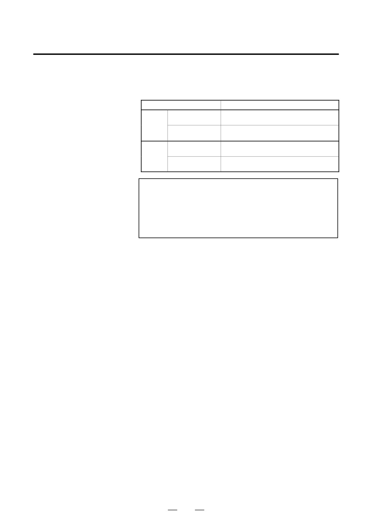
The maximum stroke controlled by this CNC is shown in the table below:
2.4
Maximum stroke+Least command increment
99999999.
MAXIMUM STROKES
Table 2.4 Maximum strokes
Increment system
Maximum strokes
Metric machine
"99999.999 mm
system
"99999.999 deg
IS-B
Inch machine
"9999.9999 inch
system
"99999.999 deg
Metric machine
"9999.9999 mm
system
"9999.9999 deg
IS-C
Inch machine
"999.99999 inch
system
"9999.9999 deg
NOTE
1
The unit in the table 2.4 is a diameter value with diameter
programming and a radius value in radius programming.
2
A command exceeding the maximum stroke cannot be
specified.
3
The actual stroke depends on the machine tool.
36
3. PREPARATORY FUNCTION
B-63524EN/01
PROGRAMMING
(G FUNCTION)
PREPARATORY FUNCTION (G FUNCTION)
3
A number following address G determines the meaning of the command
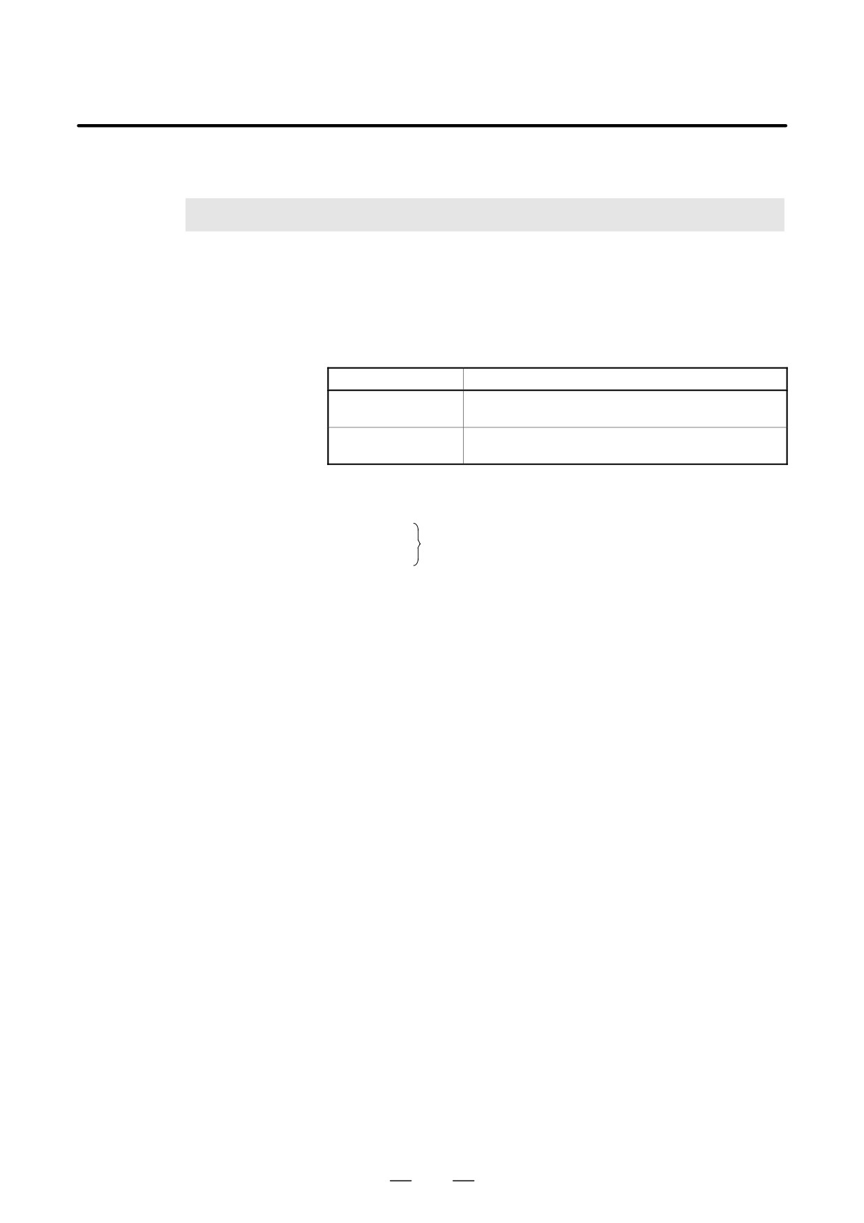
for the concerned block.
G codes are divided into the following two types.
Type
Meaning
One-shot G code
The G code is effective only in the block in which it is
specified
Modal G code
The G code is effective until another G code of the
same group is specified.
(Example)
G01 and G00 are modal G codes.
G01X_;
Z_;
G01 is effective in this range
X_;
G00Z_;
There are three G code systems : A,B, and C (Table 3). Select a G code
system using bits 6 (GSB) and 7 (GSC) of parameter 3401. To use G code
system B or C, the corresponding option is needed. Generally, this
manual describes the use of G code system A, except when the described
item can use only G code system B or C. ln such cases, the use of G code
system B or C is described.
37
3. PREPARATORY FUNCTION
(G FUNCTION)
PROGRAMMING
B-63524EN/01
Explanations
1.
If the CNC enters the clear state (see bit 6 (CLR) of parameter 3402)
when the power is turned on or the CNC is reset, the modal G codes
change as follows.
(1) G codes marked with
in Table 3 are enabled.
(2) When the system is cleared due to power-on or reset, whichever
specified, either G20 or G21, remains effective.
(3) Bit 7 of parameter No. 3402 can be used to specify whether G22
or G23 is selected upon power-on. Resetting the CNC to the clear
state does not affect the selection of G22 or G23.
(4) Setting bit 0 (G01) of parameter 3402 determines which code,
either G00 or G01, is effective.
(5) When G code system B or C is used, setting bit 3 (G91) of
parameter 3402 determines which code, either G90 or G91, is
effective.
2.
G codes of group 00 except G10 and G11 are single-shot G codes.
3.
P/S larm (No.010) is displayed when a G code not listed in the G code
list is specified or a G code without a corresponding option is
specified.
4.
G codes of different groups can be specified in the same block.
If G codes of the same group are specified in the same block, the G
code specified last is valid.
5.
If a G code of group 01 is specified in a canned cycle, the canned cycle
is canceled in the same way as when a G80 command is specified. G
codes of group 01 are not affected by G codes for specifying a canned
cycle.
6.
When G code system A is used, absolute or incremental programming
is specified not by a G code (G90/G91) but by an address word (X/U,
Z/W, C/H, Y/V). When G code system A is used for a drilling cycle,
only the initial level is provided at the return point.
7.
G codes are displayed for each group number.
38