FANUC Series 30i/300i/300is-MODEL A. Machining Center System. User's manual - page 287
 

  Index      Manuals     FANUC Series 30i/300i/300is-MODEL A. Machining Center System. User's manual (B-63944EN/03)


Search            copyright infringement  


Content      ..     285      286      287      288     ..


FANUC Series 30i/300i/300is-MODEL A. Machining Center System. User's manual - page 287


A.PARAMETERS

 APPENDIX 

B-63944EN/03


- 2252 - 

19698 


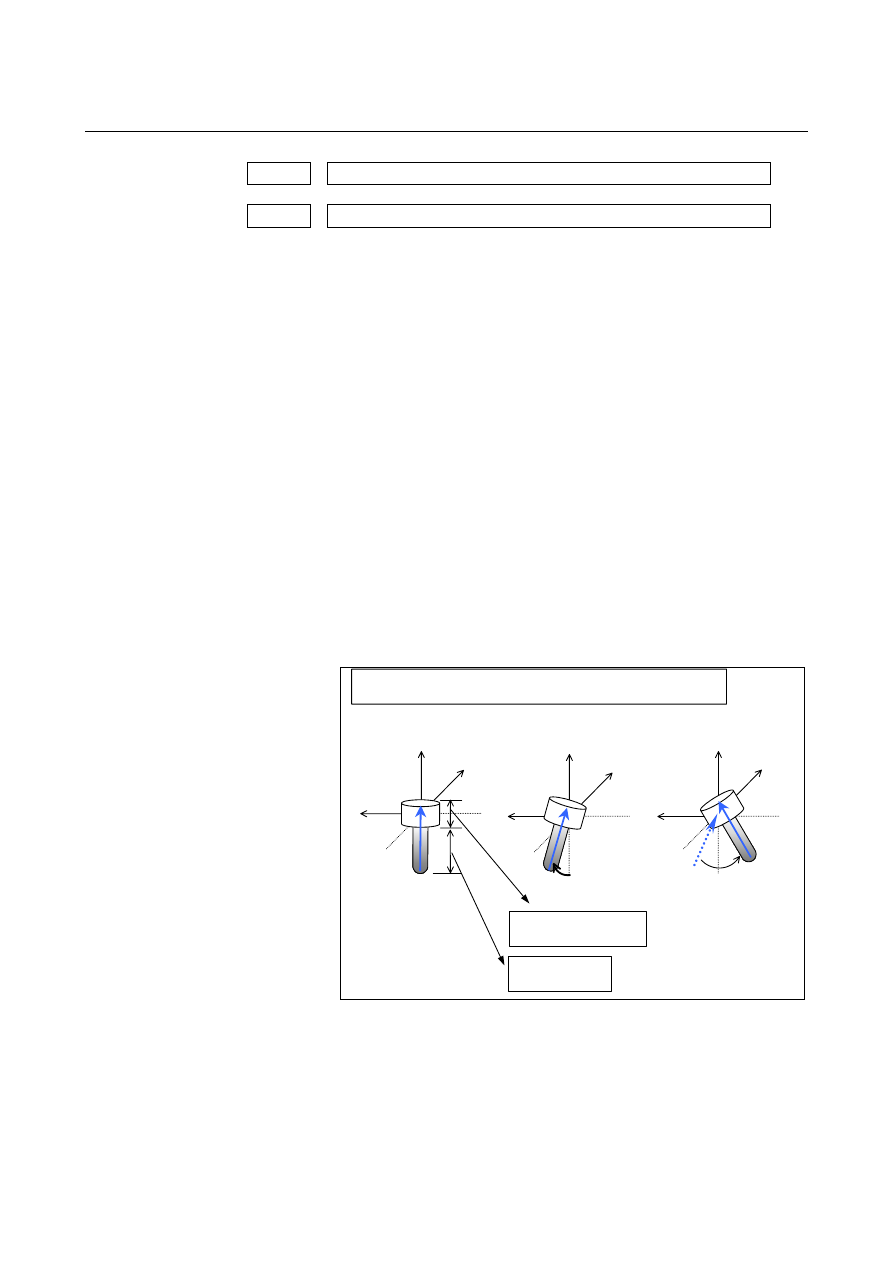
Angle when the reference tool axis direction is tilted (reference angle RA)


19699 


Angle when the reference tool axis direction is tilted (reference angle RB)


[Input type]  Parameter input 


[Data type]  Real path 


[Unit of data]  Degree 


[Minimum unit of data]  Depend on the increment system of the reference axis 

  [Valid data range]  9 digit of minimum unit of data (refer to standard parameter setting 

(When the increment system is IS-B, -999999.999 to +999999.999) 
When the reference tool axis direction (parameter No. 19697) is set to 
1, the tool axis is tilted the RA degrees on the Z-axis from the positive 
X-axis direction to positive Y-axis direction, then the tool axis is tilted 
the RB degrees on the X-axis from the positive Y-axis direction to 
positive Z-axis direction. 
When the reference tool axis direction (parameter No. 19697) is set to 
2, the tool axis is tilted the RA degrees on the X-axis from the positive 
Y-axis direction to positive Z-axis direction, then the tool axis is tilted 
the RB degrees on the Y-axis from the positive Z-axis direction to 
positive X-axis direction. 
When the reference tool axis direction (parameter No. 19697) is set to 
3, the tool axis is tilted the RA degrees on the Y-axis from the positive 
Z-axis direction to positive X-axis direction, then the tool axis is tilted 
the RB degrees on the Z-axis from the positive X-axis direction to 
positive Y-axis direction. 


Tool axis direction when the reference tool axis direction is Z-axis 

RA

X

Z

X

Y

Z

RB 

X

Tool holder offset 

Tool length offset


B-63944EN/03

 APPENDIX 

A.PARAMETERS


- 2253 - 

19700 


Rotary table position (X-axis of the basic three axes) 


19701 


Rotary table position (Y-axis of the basic three axes) 


19702 


Rotary table position (Z-axis of the basic three axes) 


[Input type]  Parameter input 


[Data type]  Real path 


[Unit of data]  mm, inch (machine unit) 


[Minimum unit of data]  Depend on the increment system of the applied axis 

 [Valid data range]  9 digit of minimum unit of data (refer to standard parameter setting 

table (A)) 
(When the increment system is IS-B, -999999.999 to +999999.999) 
Set these parameters when parameter No. 19680 is set to 12 or 21. The 
vector from the origin of the machine coordinate system to point A on 
the first rotation axis of the table is set as the rotary table position in 
the machine coordinate system. 
 

Rotary table position

Zm

Ym

Xm

First rotary axis of
table

Rotary table position

A


NOTE 


As point A, set a position that is easy to measure 
on the first rotary axis of the table. 


Set a radius value. 


If the rotary table is moved along the X-, Y-, or 
Z-axis or all of these axes, set the position of the 
rotary table when the machine coordinates of the 
X-, Y-, and Z-axes are all set to 0. 


A.PARAMETERS

 APPENDIX 

B-63944EN/03


- 2254 - 

19703 


Intersection offset vector between the first and second rotation axes of the 

table (X-axis of the basic three axes) 


19704 


Intersection offset vector between the first and second rotation axes of the 

table (Y-axis of the basic three axes) 


19705 


Intersection offset vector between the first and second rotation axes of the 

table (Z-axis of the basic three axes) 


[Input type]  Parameter input 


[Data type]  Real path 


[Unit of data]  mm, inch (machine unit) 


[Minimum unit of data]  Depend on the increment system of the applied axis 

 [Valid data range]  9 digit of minimum unit of data (refer to standard parameter setting 

table (A)) 
(When the increment system is IS-B, -999999.999 to +999999.999) 
Set these parameters when the first rotation axis and second rotation 
axis of the table do not intersect. These parameters are valid when 
parameter No. 19680 is set to 12. When the rotation axes for 
controlling the table are all at 0 degrees, the vector from point A to 
point B on the second rotation axis of the table is set as the 
intersection offset vector in the machine coordinate system. 
 

When table rotary axes do not intersect

Zm

Ym

Xm

Second rotary axis of table

First rotary axis of
table

Rotary table position

Intersection offset vector between first and second rotary
axes of table

B

A


NOTE 


As point B, set a position that is easy to measure 
on the second rotary axis of the table. 


Set a radius value. 


B-63944EN/03

 APPENDIX 

A.PARAMETERS


- 2255 - 

19709 

  Intersection offset vector between the tool axis and tool rotation axis (X-axis 

of the basic three axes) 


19710 

  Intersection offset vector between the tool axis and tool rotation axis (Y-axis 

of the basic three axes) 


19711 

  Intersection offset vector between the tool axis and tool rotation axis (Z-axis 

of the basic three axes) 


[Input type]  Parameter input 


[Data type]  Real path 


[Unit of data]  mm, inch (machine unit) 


[Minimum unit of data]  Depend on the increment system of the applied axis 

 [Valid data range]  9 digit of minimum unit of data (refer to standard parameter setting 

table (A)) 
(When the increment system is IS-B, -999999.999 to +999999.999) 
Set these parameters when the tool axis and tool rotation axis do not 
intersect. 
These parameters are valid when parameter No. 19680 is set to 2 or 
21. 
If parameter No. 19680 is 21, set the vector from point D on the tool 
axis to point E determined on the tool rotation axis as the intersection 
offset vector in the machine coordinate system when the rotation axes 
for controlling the tool are all at 0 degrees. 
If parameter No. 19680 is 2, set the vector from point D on the tool 
axis to point E determined on the second rotation axis of the tool as 
the intersection offset vector in the machine coordinate system when 
the rotation axes for controlling the tool are all at 0 degrees. 
 

When tool axis and tool rotary axis do not intersect

Tool length offset

Tool holder offset

Intersection offset vector between tool axis and
tool rotary axis

D

E

Tool center point

Controlled point

Tool rotary
axis


NOTE 


Point D is determined by adding the tool length 
offset and tool holder offset (parameter No. 19666) 
to the tool tip. As point E, set a position that is easy 
to measure. 


Set a radius value. 


A.PARAMETERS

 APPENDIX 

B-63944EN/03


- 2256 - 

19712 


Intersection offset vector between the second and first rotation axes of the 

tool (X-axis of the basic three axes) 


19713 


Intersection offset vector between the second and first rotation axes of the 

tool (Y-axis of the basic three axes) 


19714 


Intersection offset vector between the second and first rotation axes of the 

tool (Z-axis of the basic three axes) 


[Input type]  Parameter input 


[Data type]  Real path 


[Unit of data]  mm, inch (machine unit) 


[Minimum unit of data]  Depend on the increment system of the applied axis 

 [Valid data range]  9 digit of minimum unit of data (refer to standard parameter setting 

table (A)) 
(When the increment system is IS-B, -999999.999 to +999999.999) 
Set these parameters when the rotation axes of the tool do not 
intersect. 
These parameters are valid when parameter No. 19680 is set to 2. 
Set the vector from point E on the second rotation axis of the tool to 
point F on the first rotation axis of the tool as the intersection offset 
vector in the machine coordinate system when the rotation axes for 
controlling the tool are all at 0 degrees. 


When tool axis and tool rotary axis do not intersect 

Tool length offset

Tool holder offset 

Intersection offset vector between tool axis and second 
rotary axis of tool 

D

E

Tool center point 

Controlled point 

Second rotary 
axis of tool 

F

First rotary axis of tool 

Intersection offset vector between second and first 
rotary axes of tool 


NOTE 


As point F, set a position that is easy to measure. 


Set a radius value. 


B-63944EN/03

 APPENDIX 

A.PARAMETERS


- 2257 - 

19738 


Angle to check if Tool posture is near Singular posture or not 


[Input type]  Parameter input 


[Data type]  Real path 


[Unit of data]  degree 


[Minimum unit of data]  Depend on the increment system of the reference axis 

 [Valid data range]  9 digit of minimum unit of data (refer to standard parameter setting 

table(A)) 
(When the increment system is IS-B, -999999.999 to +999999.999) 
In the case of tool posture control for tool center point control (type II), 
when the difference(angle) between a tool posture and the singular 
posture is less than this parameter, the tool posture is regarded as ‘near 
the singular posture’. Then, the tool posture at the block end is 
changed so that the tool posture passes the singular posture during the 
block. 
If this parameter is 0.0, the tool posture at the block end is not 
changed. 
 

19739 


Angle to decide that the tool posture at block end is not changed 


[Input type]  Parameter input 


[Data type]  Real path 


[Unit of data]  degree 


[Minimum unit of data]  Depend on the increment system of the reference axis 

 [Valid data range]  9 digit of minimum unit of data (refer to standard parameter setting 

table(A)) 
(When the increment system is IS-B, -999999.999 to +999999.999) 
When an appropriate value is set in parameter No. 19738 in tool 
posture control for tool center point control (type II), a tool posture 
near the singular point may occur during the execution of a block. If 
this happens, change the tool posture at the end point so that the 
singular posture is passed within the block. With respect to the angle 
of the rotation axis nearer to the workpiece before and after the tool 
posture is changed (the rotation axis is the master axis when tehe tool 
turns, the slave axis when the table turns, or the table roration axis 
when the rotation is of the mixed type), however, the tool posture 
must not be changed if both the difference between the angle after the 
change and (angle before the change 

+

 180 degrees) and the difference 

between the angle after the change and (angle before the change 

 180 

degrees) are equal to or greater than the value set in the parameter,   
 

A.PARAMETERS

 APPENDIX 

B-63944EN/03


- 2258 - 

19741 


Upper limit of the movement range of the first rotation axis 


[Input type]  Parameter input 


[Data type]  Real path 


[Unit of data]  Degree 


[Minimum unit of data]  Depend on the increment system of the reference axis 

  [Valid data range]  9 digit of minimum unit of data (refer to standard parameter setting 

(When the increment system is IS-B, -999999.999 to +999999.999) 
This parameter sets the upper limit of the movement range of the first 
rotation axis in tool center point control (type 2), 3-dimensional cutter 
compensation (type 2), or tool axis direction control of the tilted 
working plane command (G53.1). When the movement range of the 
first rotation axis is not specified, this parameter and parameter No. 
19742 must both be set to 0. 
 

19742 


Lower limit of the movement range of the first rotation axis 


[Input type]  Parameter input 


[Data type]  Real path 


[Unit of data]  Degree 


[Minimum unit of data]  Depend on the increment system of the reference axis 

  [Valid data range]  9 digit of minimum unit of data (refer to standard parameter setting 

(When the increment system is IS-B, -999999.999 to +999999.999) 
This parameter sets the lower limit of the movement range of the first 
rotation axis in tool center point control (type 2), 3-dimensional cutter 
compensation (type 2), or tool axis direction control of the tilted 
working plane command (G53.1). When the movement range of the 
first rotation axis is not specified, this parameter and parameter No. 
19741 must both be set to 0. 
 

19743 


Upper limit of the movement range of the second rotation axis 


[Input type]  Parameter input 


[Data type]  Real path 


[Unit of data]  Degree 


[Minimum unit of data]  Depend on the increment system of the reference axis 

  [Valid data range]  9 digit of minimum unit of data (refer to standard parameter setting 

(When the increment system is IS-B, -999999.999 to +999999.999) 
This parameter sets the upper limit of the movement range of the 
second rotation axis in tool center point control (type 2), 
3-dimensional cutter compensation (type 2), or tool axis direction 
control of the tilted working plane command (G53.1). When the 
movement range of the second rotation axis is not specified, this 
parameter and parameter No. 19744 must both be set to 0. 
 

B-63944EN/03

 APPENDIX 

A.PARAMETERS


- 2259 - 

19744 


Lower limit of the movement range of the second rotation axis 


[Input type]  Parameter input 


[Data type]  Real path 


[Unit of data]  Degree 


[Minimum unit of data]  Depend on the increment system of the reference axis 

  [Valid data range]  9 digit of minimum unit of data (refer to standard parameter setting 

(When the increment system is IS-B, -999999.999 to +999999.999) 
This parameter sets the lower limit of the movement range of the 
second rotation axis in tool center point control (type 2), 
3-dimensional cutter compensation (type 2), or tool axis direction 
control of the tilted working plane command (G53.1). When the 
movement range of the second rotation axis is not specified, this 
parameter and parameter No. 19743 must both be set to 0. 


#7 #6 #5 #4 #3 #2 #1 #0 

19746 


 CRS  TBP 

LOZ 

LOD 

PTD  


[Input type]  Parameter input 


[Data type]  Bit path 


        # 1 

PTD

  When 3-dimensional cutter compensation is performed for a table 

rotation type machine, the direction of the tool is: 
0:  Specified by parameter Nos. 19697, 19698, and 19699. 
1:  Specified as a direction perpendicular to the plane specified by 

G17, G18, or G19. 


        # 2 

LOD

  As the tool length for three-dimensional machining manual feed: 

0:  The value of parameter No. 12318 is used. 
1:  The tool length currently used for tool length compensation is 

used. 


        # 3 

LOZ

  When bit 2 (LOD) of parameter No. 19746 is set to 1 and tool length 

compensation is not applied, as the tool length for three-dimensional 
machining manual feed: 
0:  The value of parameter No. 12318 is used. 
1:  0 is used. 
 

        # 4 

TBP

  For a 5-axis machine having a table rotation axis, as the programming 

coordinate system for 3-dimensional tool compensation machining: 
0:  The workpiece coordinate system is used. 
1:  The setting of bit 5 (WKP) of parameter No. 19696 is used. 


Content      ..     285      286      287      288     ..