FANUC Series 30i/300i/300is-MODEL A. Machining Center System. User's manual - page 186
 

  Index      Manuals     FANUC Series 30i/300i/300is-MODEL A. Machining Center System. User's manual (B-63944EN/03)


Search            copyright infringement  


Content      ..     184      185      186      187     ..


FANUC Series 30i/300i/300is-MODEL A. Machining Center System. User's manual - page 186


12.SETTING AND DISPLAYING DATA

 OPERATION 

B-63944EN/03


- 1444 - 

12.1.8 

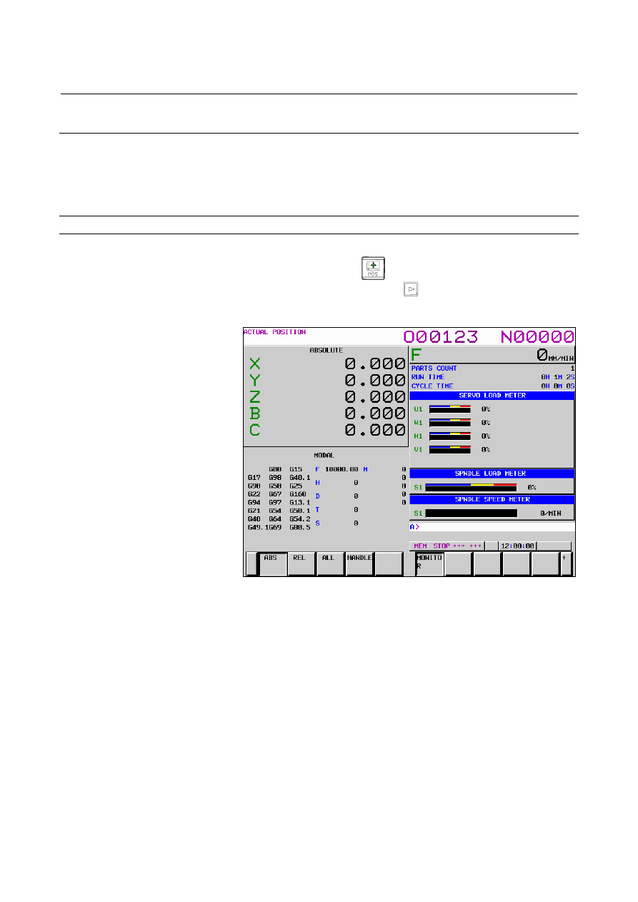
Operating Monitor Display 

 
The load meter for a servo axis can be displayed. Also, the load meter 
and speed meter for a serial spindle can be displayed. 
To enable this function, bit 5 (OPM) of parameter No. 3111 must be 
set to 1. 
 

Procedure for displaying the operating monitor 

Procedure 

Press function key 

Press continuous menu key 

Press soft key [MONITOR].   


Fig. 12.1.8 (a) Operating monitor (M series) (10.4-inch) 


B-63944EN/03

 OPERATION 

12.SETTING AND DISPLAYING DATA


- 1445 - 


Fig. 12.1.8 (b) Operating monitor (T series) (10.4-inch) 


Explanation 
  - Display of the servo axes 

Servo axis load meters as many as the maximum number of controlled 
axes of the path can be displayed. One screen displays load meters for 
up to five axes at a time. By pressing the soft key [MONITOR], load 
meters for the 6th axis and up are displayed.   
 

  - Display of the spindle axes 

When serial spindles are used, the reading on the load meter and 
speedometer can be displayed only for the main serial spindle. 
 

  - Unit of graph 

The bar graph for the load meter shows load up to 200% (only a value 
is displayed for load exceeding 200%).   
The bar graph for the speedometer shows the ratio of the current 
spindle speed to the maximum spindle speed (100%). 
 

 - Load meter 

The reading on the load meter depends on servo parameter No. 2086 
and spindle parameter No. 4127.   
 

12.SETTING AND DISPLAYING DATA

 OPERATION 

B-63944EN/03


- 1446 - 

 - Speedometer 

Although the speedometer normally indicates the speed of the spindle 
motor, it can also be used to indicate the speed of the spindle by setting 
bit 6 (OPS) of parameter No. 3111 to 1. 
The spindle speed to be displayed during operation monitoring is 
calculated from the speed of the spindle motor (see the formula below).   
The spindle speed can therefore be displayed, during operation 
monitoring, even when no position coder is used.   
To display the correct spindle speed, however, the maximum spindle 
speed for each gear (spindle speed at each gear ratio when the spindle 
motor rotates at the maximum speed) must be set in parameters No. 
3741 to No.3744. 
The input of the clutch and gear signals for the first serial spindle is 
used to determine the gear which is currently selected. Control the 
input of the CTH1A and CTH2A signals according to the gear 
selection, by referring to the table below. 
(Formula for calculating the spindle speed to be displayed) 

Maximum spindle speed
with the gear being used

Maximum speed of
spindle motor

Speed of spindle motor

Spindle speed displayed
during operation monitoring =

×


The following table lists the correspondence between clutch and gear 
selection signals CTH1A and CTH2A, used to determine the gear 
being used, and parameters: 

CTH1A CTH2A

Parameter 

Serial spindle 

specification 

0 0 

=No.3741 (Maximum spindle speed 
with gear 1) 

HIGH 

0 1 

=No.3742 (Maximum spindle speed 
with gear 2) 

MEDIUM HIGH 

1 0 

=No.3743 (Maximum spindle speed 
with gear 3) 

MEDIUM LOW 

1 1 

=No.3744 (Maximum spindle speed 
with gear 4) 

LOW 

 
The speed of the spindle motor and spindle can be displayed, during 
operation monitoring, only for the first serial spindle and the spindle 
switching axis for the first serial spindle. It cannot be displayed for the 
second spindle. 
 

  - Color of graph 

If the value of a load meter exceeds 100%, the bar graph turns purple. 
 

B-63944EN/03

 OPERATION 

12.SETTING AND DISPLAYING DATA


- 1447 - 

12.1.9 

Display of Three-dimensional Manual Feed (Tool Tip 

Coordinates, Number of Pulses, Machine Axis Move Amount) 

 
The absolute coordinates of the tool tip, the number of pulses, and a 
machine axis move amount based on three-dimensional manual feed 
are displayed. 
 

Displaying the screen for three-dimensional manual feed 

Procedure 

Press function key 

Press the continuous menu key 

  several times to display the 

soft key [3-D MANUAL]. 

3  Press the soft key [3-D MANUAL] to display the screen of 

three-dimensional manual feed. 


Fig. 12.1.9 (a) Three-dimensional manual feed screen(10.4-inch) 


12.SETTING AND DISPLAYING DATA

 OPERATION 

B-63944EN/03


- 1448 - 

Explanation 
  - Tool tip position 

The addresses of the three basic machine configuration axes for 
performing three-dimensional manual feed and the current position of 
the tool tip are displayed. 
 

  - Tool axis reference (number of pulses) 

TD 


The amount of travel in the tool axis direction in tool axis 
direction handle feed, tool axis direction jog feed, or tool axis 
direction incremental feed is displayed. 
The unit is the least input increment of the axis in the direction 
specified by parameter No. 19697. 


R1 


The amount of travel in the first axis direction in tool axis 
right-angle direction handle feed, tool axis right-angle direction 
jog feed, or tool axis right-angle direction incremental feed is 
displayed. 


The unit is the least input increment of the axis in the first axis 
direction normal to the direction specified by parameter No. 
19697. 


R2 


The amount of travel in the second axis direction in tool axis 
right-angle direction handle feed, tool axis right-angle direction 
jog feed, or tool axis normal direction incremental feed is 
displayed. 


The unit is the least input increment of the axis in the second axis 
direction normal to the direction specified by parameter No. 
19697. 


  - Tool tip center (number of pulses) 

C1 


The angular displacement in tool tip center rotation handle feed, 
tool tip center rotation jog feed, or tool tip center rotation 
incremental feed for rotation of the first rotary axis is displayed.   
The unit is the least input increment of the first rotary axis. 


C2 


The angular displacement in tool tip center rotation handle feed, 
tool tip center rotation jog feed, or tool tip center rotation 
incremental feed for rotation of the second rotary axis is 
displayed.  The unit is the least input increment of the second 
rotary axis. 


B-63944EN/03

 OPERATION 

12.SETTING AND DISPLAYING DATA


- 1449 - 

  - Table reference (number of pulses) 

VR 


The amount of travel in the table reference vertical direction in 
table reference vertical direction handle feed, table reference 
vertical direction jog feed, or table reference vertical direction 
incremental feed is displayed. 


The unit is the least input increment of the axis in the direction 
specified by parameter No. 19697. 


H1 


The amount of travel in the first axis direction in table reference 
horizontal direction handle feed, table reference horizontal 
direction jog feed, or table reference horizontal direction 
incremental feed is displayed. 


The unit is the least input increment of the axis in the first axis 
direction normal to the direction specified by parameter No. 
19697. 


H2 


The amount of travel in the second axis direction in table 
reference horizontal direction handle feed, table reference 
horizontal direction jog feed, or table reference horizontal 
direction incremental feed is displayed. 


The unit is the least input increment of the axis in the second axis 
direction normal to the direction specified by parameter No. 
19697. 


  - Amounts of machine axis travel 

The addresses of machine configuration axes used for 
three-dimensional manual feed and the sum of the amount of travel of 
each axis used for three-dimensional manual feed are displayed. 
The values of the basic three axes (X-axis, Y-axis, and Z-axis), the 
first rotary axis, and the second rotary axis are displayed in this order. 
For the definition of the first rotary axis and second rotary axis, see 
the description of parameter No. 19680. 
When bit 0 (CLR) of parameter No. 13113 is set to 1, the displayed 
data is cleared by a reset. 
 

  - Absolute coordinates, machine coordinates 

The absolute coordinates and machine coordinates of all axes are 
displayed. If too many axes are involved for display on one screen, the 
remaining axes can be displayed by pressing the soft key [3-D 
MANUAL] for page feed. 
 

 - F (feedrate) 


When bit 3 (CFD) of parameter No. 13113 is set to 0 


The composite feedrate at a control point on a linear axis or 
rotary axis is displayed. 


When bit 3 (CFD) of parameter No. 13113 is set to 1 


The feedrate of the tool tip is displayed. 


12.SETTING AND DISPLAYING DATA

 OPERATION 

B-63944EN/03


- 1450 - 

Operation 

The display of the number of pulses can be cleared by soft key 
operations. 
 

Press soft key [(OPRT)].   


2      Select the soft key corresponding to a function subject to clearing 

of the amount of travel.   
  Pressing the rightmost soft key displays the second page. 


3  Press soft key [ERASE] to clear the amount of travel of the 

specified function. Press soft key [CAN] to cancel erase 
operation. 


Screens of a 15-inch display unit 

 
Press function key 

 to display the current overall position 

display screen that shows the current position of the tool. 
The above screen can also display the feedrate, run time, and the 
number of parts. In addition, a floating reference position can be set 
on this screen. 
Function key 

  can also be used to display the load on the servo 

motor and spindle motor and the rotation speed of the spindle motor 
(operating monitor display). 
Function key 

 can also be used to display the screen for 

displaying the distance moved by handle interruption. See III-4.6 for 
details on this screen. 
 

B-63944EN/03

 OPERATION 

12.SETTING AND DISPLAYING DATA


- 1451 - 

12.1.10 

Overall Position Display (15-inch Display Unit) 

 
Displays the following positions on a screen : Current positions of the 
tool in the workpiece coordinate system, relative coordinate system, 
and machine coordinate system, and the remaining distance.   
The relative coordinates can also be set on this screen.


(Refer to 

Explanation.) 
 

Procedure for displaying overall position display screen 

Procedure 

Press function key 

Press vertical soft key [ALL].   


Fig. 12.1.10 (a) Current position screen (M series) (15-inch) 


Fig. 12.1.10 (b) Current position screen (T series) (15-inch) 


Content      ..     184      185      186      187     ..