FANUC Series 30i/300i/300is-MODEL A. Machining Center System. User's manual - page 104
 

  Index      Manuals     FANUC Series 30i/300i/300is-MODEL A. Machining Center System. User's manual (B-63944EN/03)


Search            copyright infringement  


Content      ..     102      103      104      105     ..


FANUC Series 30i/300i/300is-MODEL A. Machining Center System. User's manual - page 104


22.5-AXIS MACHINING FUNCTION

 PROGRAMMING 

B-63944EN/03


- 788 - 

Explanation 
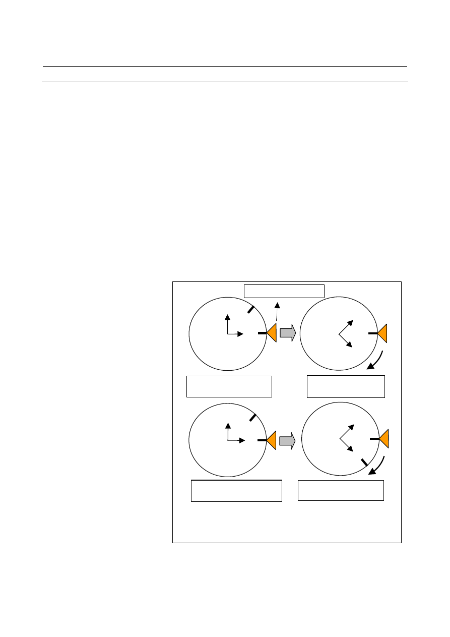
  - When a coordinate system fixed on the table is used as the programming 

coordinate system 

The programming coordinate system is used for tool center point 
control.    When the G43.4 or G43.5 command is specified with bit 5 
(WKP) of parameter No.19696 set to 0, the workpiece coordinate 
system that is fixed on the table at that point of time becomes the 
programming coordinate system.  Thereafter, the programming 
coordinate system rotates as the table turns around. 
It does not rotate with the tool head. 
X, Y, and Z mentioned hereinafter are assumed to be commanded on 
the programming coordinate system. 
When the G43.4 or G43.5 command is specified or when the rotary 
axis of the table has moved in a block preceding G43.4 or G43.5, the 
angle of the table's rotary axis represents the initial state of the 
programming coordinate system. 
In the case of type 2, the tool direction seen from the coordinate 
system that is fixed on the table is specified by I, J, K. 
In the descriptions that follow, the table-fixed coordinate system is 
represented by X', Y', and Z'. 

When G43.4 or G43.5 is 
specified with C = 0 
d

Tool center point control 
in progress 

X'

Y'

Workpiece 
coordinate 
system 

0

45

X' 

Y' 

C

Programming 
coordinate system 

45 

Tool center point control in 
progress


C-axis reference position

X'

Y'

45

90

Workpiece 
coordinate 
system 

When G43.4 or G43.5 is 
specified with C = 45 degrees

X' 

C

Programming 
coordinate system 

90 

45 

The C-axis reference position is the position where a movement is 
made on the C-axis so that a command value for the C-axis is at the 
scale position on the table. 

Y' 


Fig. 22.1 (f)    Programming coordinate system fixed on the table 


B-63944EN/03

 PROGRAMMING 

22.5-AXIS MACHINING FUNCTION


- 789 - 

  - When the workpiece coordinate system is used as the programming coordinate 

system 

When the G43.4 command is specified with bit 5 (WKP) of parameter 
No.19696 set to 1, the workpiece coordinate system that is in use at 
that point of time becomes the programming coordinate system. 
In this case, the programming coordinate system does not rotate as the 
table turns around but remains fixed on the workpiece coordinate 
system. 
Hereinafter, when X, Y, and Z are commanded, the tool moves along 
a straight line toward the table (workpiece).    For X, Y, Z, specify the 
end point location after the rotation of the table, as seen from the 
programming coordinate system. 
Type 2 cannot be used.  Specifying G43.5 when bit 5 (WKP) of 
parameter No.19696 set to 1 causes alarm PS5459. 
In the descriptions that follow, the coordinate values of the workpiece 
coordinate system used as the programming coordinate system are 
represented by X", Y", and Z". 


When G43.4 is specified
with C = 0 degrees 

Tool center point control
in progress 

X"

Y"

Workpiece 
coordinate 
system 

0

45

C

Programming 
coordinate 
system


45 

Tool center point control in 

progress 

C-axis reference position

45

90

Workpiece 
coordinate 
system 

X"

Y"

When G43.4 is specified with 
C = 45 degrees 

C

Programming 
coordinate 
system 

90 

45 

X" 

Y" 

X" 

Y" 

The C-axis reference position is the position where a movement is made on the 
C-axis so that a command value for the C-axis is at the scale position on the 
table.


Fig. 22.1 (g)    Programming coordinate system identical to the 

workpiece coordinate system 


22.5-AXIS MACHINING FUNCTION

 PROGRAMMING 

B-63944EN/03


- 790 - 

  - Notes on performing circular interpolation and helical interpolation when using 

the workpiece coordinate system as the programming coordinate system 


The start point, end point, and center of an arc change as the 
table rotation axis rotates. 


I, J, K commands the vector of the block start point to the center 
of the arc from the start point in the rotary axis position. 


Note the following: 
<1>  Only a table rotation axis normal to a selected plane can be 

rotated during circular interpolation.   

<2> During circular interpolation, those table rotation axes not 

normal to a selected plane must continue to be at the same 
position as when tool center point control is started. 

If <1> or <2> is not satisfied, the alarm PS5421 is issued. 
No restriction is imposed on rotation on a tool rotation axis. 


 - Program examples 


In the case of a composite type machine 


Descriptions are based on the following machine configuration. 


C-axis

Center of C-axis rotation

Z-axis

Y-axis

X-axis

B-axis

Center of B-axis rotation

Tool center point

Workpiece

coordinate system


B-63944EN/03

 PROGRAMMING 

22.5-AXIS MACHINING FUNCTION


- 791 - 


When the G17 (X-Y plane) command is executed 

After the G43.4 command, the X-Y plane is selected using the G17 
command and circular interpolation is performed by rotating the 
C-axis (table rotation axis) (including those cases where the C-axis 
moves before the G43.4 command). 

 This case corresponds to <1> 

and allows circular interpolation. 
Example) 

 : 
(G01 C90. ;) 
G43.4 H1 ; 
G17 G02 

IP


IR

  B10. C20. ; 

 : 

               IP:  Coordinates of the end point 
                              IR:    Arc radius 


When the G18 (Z-X plane) or G19 (Y-Z plane) command is executed 

After the G43.4 command, the Z-X plane is selected using the G18 
command and circular interpolation is performed without rotating the 
C-axis (including those cases where the C-axis moves before the 
G43.4 command).  

  This case corresponds to <2> and allows 

circular interpolation. 
The same is also true when the G19 command is used. 
Example) 

 : 
(G01 C90. ;) 
G43.4 H1 ; 
G18 G02 

IP


IR

 ; 

 : 

 
After the G43.4 command, the Z-X plane is selected using the G18 
command and the C-axis is rotated during circular interpolation .   


Alarm (violation of <2>) 
The same is also true when the G19 command is used. 
Example) 

 : 
G43.4 H1 ; 
G18 G02 

IP


IR

 C20. ; 

 : 

 
After the G43.4 command, the Z-X plane is selected using the G18 
command and circular interpolation is performed after rotating the 
C-axis.  

    Alarm (violation of <2>) 

The same is also true when the G19 command is used. 
Example) 

 : 
G43.4 H1 ; 
G01 C10. 
G18 G02 

IP


IR

 ; 

 : 


22.5-AXIS MACHINING FUNCTION

 PROGRAMMING 

B-63944EN/03


- 792 - 


In the case of a table rotation type machine 


Descriptions are based on the following machine configuration. 


A table rotation type machine can be considered equivalent to a 
composite type machine if any of its two table rotation axes does 
not move. 


C

Y

Z

A

Workpiece coordinate
system

  X


When the G17 (X-Y plane) command is executed 

The master axis (A-axis) moves before the G43.4 command and, after 
the G43.4 command, circular interpolation is performed without 
rotating the A- or C-axis (including those cases where the C-axis 
moves before the G43.4 command).  

  This case corresponds to 

<2> and allows circular interpolation. 
Example) 

 : 
G01 A90. (C10.); 
G43.4 H1 ; 
G17 G02 

IP


IR

 ; 

 : 

B-63944EN/03

 PROGRAMMING 

22.5-AXIS MACHINING FUNCTION


- 793 - 

 
The master axis (A-axis) moves before the G43.4 command and, after 
the G43.4 command, circular interpolation is performed using the G17 
(X-Y plane) command by rotating the C-axis, or the C-axis is rotated 
during circular interpolation.   

    Alarm (violation of <2>) 

Example) 

 : 
G01 A90.; 
G43.4 H1 ; 
G01 C10. ; 
G17 G02 

IP


IR

 ; 

 : 
 : 
G01 A90.; 
G43.4 H1 ; 
G17 G02 

IP


IR

 C10.; 

 : 

 
After the G43.4 command, the A-axis is moved and circular 
interpolation is performed using the G17 command (X-Y plane).   


Alarm (violation of <2>) 
Example) 

 : 
G43.4 H1 ; 
G01 A10. ; 
G17 G02 

IP


IR

 C10.; 

 : 

 
G19 (Y-Z plane) command is executed 
The G43.4 command is executed after moving the A-axis and circular 
interpolation is performed while rotating the A-axis using the G19 
(Y-Z plane) command.  

  This case corresponds to <1> and 

allows circular interpolation. 
Example) 

 : 
G01 A90. ; 
G43.4 H1 ; 
G19 G02 

IP


IR

 A10. ; 

 : 

 
After the G43.4 command, the C-axis is rotated and circular 
interpolation is performed using the G19 (Y-Z plane) command.   


Alarm (violation of <2>) 
Example) 


G43.4 H1 ; 
G01 C10. ; 
G19 G02 

IP


IR

 ; 

 : 

22.5-AXIS MACHINING FUNCTION

 PROGRAMMING 

B-63944EN/03


- 794 - 

When the G18 (Z-X plane) command is executed 
The G43.4 command is executed after moving the A- and C-axes, and 
circular interpolation is performed using the G18 (Z-X plane) 
command without moving any rotary axis.   

 This case corresponds 

to <2> and allows circular interpolation. 
Example) 

 : 
G01 A90. C10. ; 
G43.4 H1 ; 
G18 G02 

IP


IR

 : 

 
After the G43.4 command, circular interpolation is performed using 
the G18 command (Z-X plane) by moving any of the rotary axes.   


Alarm (violation of <2>) 
Example) 

 : 
G43.4 H1 ; 
G01 A10. (C10.) 
G18 G02 

IP


IR

 : 


  - Tool center point control command 

During tool center point control, the command specifies the location 
of each block end point as seen from the programming coordinate 
system. 
The program specifies the tool center point. 
As for the rotary axis, the command specifies the coordinate values of 

each block end point in the case of type 1 or the tool direction at each 
block end point in the case of type 2. 

The feedrate is specified by the tangential speed relative to the 
workpiece (the tool's relative speed as opposed to the workpiece), 
which is represented by F. 
 

  - Commands that can be specified during tool center point control 

The commands that can be specified during tool center point control 

are linear interpolation (G01), positioning (G00), circular 
interpolation (G02, G03), and helical interpolation (G02, G03). 

When linear interpolation (G01) is specified during tool center point 

control, speed control is exerted so that the tool center point moves at 
the specified speed. 

The circular interpolation command (G02, G03) controls the 

tangential speed of the arc path along which the tool center point 
moves. 

The helical interpolation command (G02, G03) controls the tangential 

speed of the arc path along which the tool center point moves or a 
synthetic speed including that of the helical axis.    (This is dependent 
on the setting of bit 5 (HTG) of parameter No.1403.) 

As the actual speed, the speed at the control point is shown. 
 

B-63944EN/03

 PROGRAMMING 

22.5-AXIS MACHINING FUNCTION


- 795 - 

NOTE 


When the tool center point control mode is entered, 
acceleration/deceleration before look ahead 
interpolation is enabled automatically.    Be sure to 
specify the following parameters: 

(1)  Bit 1 (LRP) of parameter No.1401=1 :     
 

Linear rapid traverse 

(2)  Bit 5 (FRP) of parameter No.19501=1 :     
 

Acceleration/deceleration before interpolation 
is used for rapid traverse. 

(3)  Parameter No.1671 :     
 

Acceleration before interpolation for rapid 
traverse. 

(4)  Parameter No.1672 :     
 

Change time for bell-shaped acceleration 
before interpolation for rapid traverse. 

(5)  Parameter No.1660 : 

Maximum permissible acceleration for 
acceleration/deceleration before interpolation 


If they are not specified, alarm PS5420 is 
generated. 


  - Rotary axis command 

If a command is specified during tool center point control that 
prohibits the tool center point from moving with respect to the 
workpiece, the maximum cutting speed (parameter No.1430) is 
assumed as the feedrate of the rotary axis when bit 6 (RFC) of 
parameter No.19696 is 0, and the speed specified by F is assumed 
when bit 6 (RFC) of parameter No.19696 is 1. 
The rotary axis command cannot be specified during tool center point 
control of type 2.    Specifying the command with type 2 causes alarm 
PS5421. 
 

  - The moving distance of the rotary axis is long compared to that of the linear axis 

If the moving distance of the rotary axis is long compared to that of 

the linear axis, the rotary axis moves faster so that the tool center 
point moves at the specified speed, possibly resulting in the tool 
center point traveling on an inadequate path. 

In such a case, it is possible to exert control to slow down the speed 

and ensure that the tool center point travels on the specified path, by 
setting bit 6 (CRS) of parameter No.19746 to 1.  When using this 
control, specify in parameter No.19751 (for rapid traverse) and 
parameter No.19752 (for cutting feed) the extent of deviation of the 
path at which the speed is to be slowed down (maximum allowable 
deviation of the path).    When 0 is specified, the least input increment 
is regarded as the maximum allowable deviation of the path. 


Content      ..     102      103      104      105     ..