FANUC Series 30i/300i/300is-MODEL A. Machining Center System. User's manual - page 92
 

  Index      Manuals     FANUC Series 30i/300i/300is-MODEL A. Machining Center System. User's manual (B-63944EN/03)


Search            copyright infringement  


Content      ..     90      91      92      93     ..


FANUC Series 30i/300i/300is-MODEL A. Machining Center System. User's manual - page 92


21.AXIS CONTROL FUNCTIONS

 PROGRAMMING 

B-63944EN/03


- 692 - 

21.1 

AXIS SYNCHRONOUS CONTROL 


Overview 

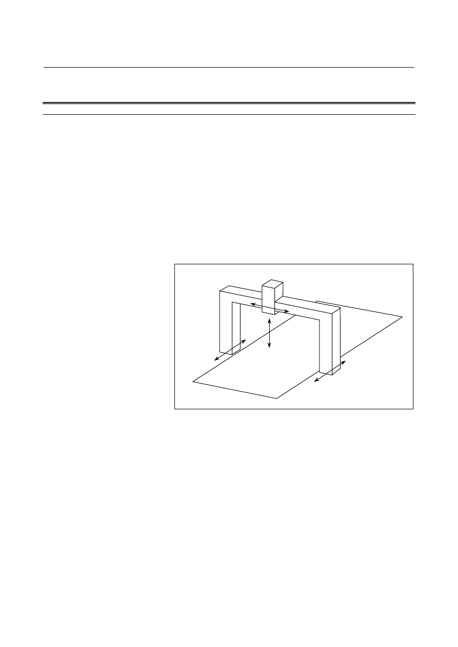
When a movement is made along one axis by using two servo motors 
as in the case of a large gantry machine, a command for one axis can 
drive the two motors by synchronizing one motor with the other.  
Moreover, by using a feedback signal from each motor, a positional 
difference (synchronous error) between the two motors is detected to 
compensate for the synchronous error.  When a synchronous error 
exceeding a set value occurs, a synchronous error check can be made 
to issue an alarm and stop a movement along the axis. 
 
An axis used as the reference for axis synchronous control is referred 
to as a master axis (M-axis), and an axis along which a movement is 
made in synchronism with the master axis is referred to as a slave axis 
(S-axis). 
 

Y

Z

A

(Slave axis)

X

(Master axis)


Fig. 21.1 (a)    Example of machine with X and A being synchronous axes 

 
Even when synchronous error compensation is not used, the 
synchronous establishment function can be used for automatic 
compensation to eliminate a machine coordinate error in cases such as 
emergency stop cancellation. 
 
An external signal can be used to turn synchronization on and off.  
When synchronization is turned on and off using an external signal, 
synchronous error compensation cannot be used. 

B-63944EN/03

 PROGRAMMING 

21.AXIS CONTROL FUNCTIONS


- 693 - 

21.1.1 

Axis Configuration for Axis Synchronous Control 


Explanation 
  - Master axis and slave axis for axis synchronous control 

An axis used as the reference for axis synchronous control is referred 
to as a master axis (M-axis), and an axis along which a movement is 
made in synchronism with the master axis is referred to as a slave axis 
(S-axis). 
By setting the axis number of a master axis in the parameter No. 8311 
of the slave axis, the axis configuration for axis synchronous control is 
determined. 
 

  - Synchronous operation and normal operation 

Operation where axis synchronous control is turned on (enabled) to 
make a movement along the slave axis in synchronism with the master 
axis is referred to as synchronous operation.  Operation where axis 
synchronous control is turned off (disabled) to make movements along 
the master axis and slave axis independently of each other is referred 
to as normal operation. 
 
(Example) 
Automatic operation when the master axis is the X-axis and the slave 
axis is the A-axis 
 

In synchronous operation, movements are made along the X-axis 
and A-axis according to the programmed command Xxxxx for 
the master axis. 


In normal operation, movements are made along the master axis 
and slave axis independently of each other as in the case of 
normal CNC control.  The programmed command Xxxxx 
makes a movement along the X-axis.  The programmed 
command Aaaaa makes a movement along the A-axis.  The 
programmed command Xxxxx Aaaaa makes movements along 
the X-axis and A-axis at the same time. 

 
The mode of operation can be switched between synchronous 
operation and normal operation by an input signal, or synchronous 
operation can be performed at all times.    Which mode to use can be 
set using bit 5 (SCA) of parameter No. 8304. 
 

  - Switching between synchronous operation and normal operation by using an 

input signal 

When bit 5 (SCA) of parameter No. 8304 is set to 0 for the slave axis, 
the signal SYNCx/SYNCJx (with x representing a slave axis number) 
is used to switch between synchronous operation and normal 
operation.  When SYNCx/SYNCJx = 1, synchronous operation is 
selected.    When SYNCx/SYNCJx = 0, normal operation is selected. 
Synchronous error compensation cannot be used when the mode of 
operation is switched between synchronous operation and normal 
operation. 
During feed axis synchronization control, the output signal SYNOx is 
set to "1". 

21.AXIS CONTROL FUNCTIONS

 PROGRAMMING 

B-63944EN/03


- 694 - 

  - Setting for using synchronous operation at all times 

When bit 5 (SCA) of parameter No. 8304 for the slave axis is set to 1, 
synchronous operation is performed at all times, regardless of the 
setting of the signal SYNCx/SYNCJx. 
 

  - Synchronous control axis name 

The name of a master axis and the name of a slave axis may be the 
same or may be different from each other. 
 

  - Restrictions on using the same name for the master axis and slave axis 

If the same axis name is assigned to the master axis and slave axis, 
manual operation only is allowed in normal operation.  Automatic 
operation and manual numeric command cannot be performed. 
 

  - Setting of an axis name subscript 

A subscript can be attached to an axis name like X1, X2, XM, and XS.   
If the same axis name is used for multiple axes, and a unique subscript 
is assigned to each of those axes, the axes can be distinguished from 
each other on the screen display, or which of those axes issued an 
alarm can be identified. 
Set a subscript in parameter No. 3131. 
 

  - Setting of multiple slave axes 

One master axis can have multiple slave axes. 
 
(Example) 
 

In the example below, movements along the X1-axis and X2-axis 
are made in synchronism with the XM-axis. 


Axis name 

indication 

Controlled 

axis number

Axis name

Parameter 

(No. 1020)

Subscript

Parameter 

(No.3131)

Master axis 

number 

Parameter 

(No.8311) 

Operation 

XM 1  88 77  0 


Y 2 89 

0  0 


X1 3 88 

49  1 

A movement is made 
in synchronism with 
the XM-axis. 

X2 4 88 

50  1 

A movement is made 
in synchronism with 
the XM-axis. 

 
When one master axis has multiple slave axes, synchronous error 
compensation, synchronous establishment, and synchronous error 
check are performed for each slave axis independently. 
 

  - Combination with tandem control 

Tandem control can be used with each of the master and slave axes.   
The same restriction on axis arrangement as imposed in the case of 
normal tandem control is imposed.  No particular restriction is 
imposed on axis synchronous control. 
 

B-63944EN/03

 PROGRAMMING 

21.AXIS CONTROL FUNCTIONS


- 695 - 

  - Axis selection on the screen display 

On a screen such as the current position display screen, a slave axis is 
also displayed.    The display of a slave axis can be disabled by setting 
bit 0 (NDP) of parameter No. 3115 to 1 and setting bit 1 (NDA) of 
parameter No. 3115 to 1. 
 

  - Axis selection in actual cutting feedrate display 

By setting bit 2 (SAF) of parameter No. 8303 to 1 for a slave axis, the 
slave axis can be included in an actual cutting feedrate display 
calculation during synchronous operation. 
 

  - Axis synchronous control with an absolute-position detector 

When bit 7 (SMA) of parameter No. 8302 is set to 1 to attach an 
absolute-position detector, and bit 4 (APZ) of parameter No. 1815 for 
an axis placed in synchronous operation is turned off, APZ for the axis 
(axes) placed together in synchronous operation is also turned off. 
 

  - Slave axis mirror image 

By setting parameter No. 8312, a mirror image can be applied to a 
slave axis placed in synchronous operation.    When the mirror image 
function is enabled, the direction in which the absolute and relative 
coordinates change is the same as for the machine coordinates. 
At this time, synchronization error compensation, synchronization 
establishment, synchronization error check, and correction mode 
cannot be used. 
The mirror image set by bit 0 (MIR) of parameter No. 0012 cannot be 
applied to the slave axis.    Because this mirror image differs from the 
mirror image set by parameter MIR, it does not affect input signal MIx 
<G106> or output signal MMIx <F108>. 
 

  - External machine coordinate system shift 

Bit 7 (SYE) of parameter No. 8304 can be set to 1 for the slave axis to 
shift the slave axis by the same amount as specified for the master axis 
when external machine coordinate system shift is specified by external 
data input/output for the master axis in synchronous control. 


21.AXIS CONTROL FUNCTIONS

 PROGRAMMING 

B-63944EN/03


- 696 - 

21.1.2 

Synchronous Error Compensation 


Explanation 

When a synchronous error value exceeding the zero width set in 
parameter No. 8333 is detected, compensation pulses for synchronous 
error reduction are calculated and added onto the command pulses 
output for the slave axis.  This compensation is not performed in 
servo-off state, servo alarm state, follow-up operation, and 
modification mode. 
Compensation pulses are calculated by multiplying the synchronous 
error value between master and slave axes by a compensation gain. 

Compensation pulses = synchronous error 

×

 (Ci/1024) 

Ci:    Compensation gain (parameter No. 8334) 

 
Before synchronous error compensation can be performed, bit 5 
(SCA) of parameter No. 8304 must be set to 1 to perform synchronous 
operation at all times.  Furthermore, the first synchronous 
establishment after power-up must already be performed by a manual 
reference position return or another operation. 
 

K

1

Compensation

pulse counter

Added to command for

slave axis

Master axis

machine position

Slave axis machine
position

Compensation gain

Compensation pulses

+

-

Synchronous
error counter


  - Synchronous error compensation smooth suppress function 

When bit 6 (SMS) of parameter No. 8304 is set to 1, the synchronous 
error compensation smooth suppress function is enabled.    With this 
function, another set of parameters for a synchronous error zero width 
and synchronous error compensation gain (B and Ks in the figure 
below) can be set.  So, even a small synchronous error can be 
reduced smoothly as shown below. 
 

Synchronous error compensation gain

Synchronous error value

Kd

0

A

Ks

B


A:  Synchronous error zero width (parameter No. 8333) 
B:  Synchronous error zero width 2 (parameter No. 8335)   

(0 < B < A) 

Kd:  Synchronous error compensation gain (parameter No. 8334) 

B-63944EN/03

 PROGRAMMING 

21.AXIS CONTROL FUNCTIONS


- 697 - 

Ks: Synchronous error compensation gain 2 (parameter No. 

8336) (0 < Ks < Kd) 

Er:  Synchronous error value between the current master axis 

and slave axis 

K:  Current synchronous error compensation gain for Er 

 
1.  When Er < B, compensation is not performed.    (K = 0) 
2.  When B < Er < A 

Ks +

K

(Er - B)(Kd - Ks)

=

A - B


Compensation is performed with the above gain: 

3.  When Er > A, compensation is performed with a gain of K = Kd. 
 

21.AXIS CONTROL FUNCTIONS

 PROGRAMMING 

B-63944EN/03


- 698 - 

21.1.3 

Synchronous Establishment 


Explanation 

Upon power-up or after emergency stop cancellation, the machine 
positions on the master axis and slave axis under axis synchronous 
control are not always the same.  In such a case, the synchronous 
establishment function matches the machine position on the master 
with that on the slave axis. 


  - Synchronous establishment method 

The method of synchronous establishment used when synchronous 
error compensation is performed differs from that used when 
synchronous error is not performed. 


  - Synchronous establishment based on synchronous error compensation 

When synchronous error compensation is performed (when bit 3 
(CLP) of parameter No. 8304 for the slave axis is set to 1), 
synchronous establishment is performed in the same way as 
synchronous error compensation.  This means that the positional 
difference between the master axis and slave axis is regarded as a 
synchronous error, and pulses produced by multiplying the positional 
difference by a synchronous error compensation gain are output for 
the slave axis.  So, the parameter No. 8334 for specifying a 
synchronous error compensation gain must be set before synchronous 
establishment can be performed. 
If the parameter No. 8333 for specifying a synchronous error 
compensation zero width is set, no further synchronous establishment 
is performed after the positional difference between the master axis 
and slave axis becomes the zero width or below. 


  - Synchronous establishment based on machine coordinates 

To perform synchronous establishment when synchronous error 
compensation is disabled (when bit 3 (CLP) of parameter No. 8304 for 
the slave axis is set to 0), enable synchronous establishment based on 
machine coordinates by setting bit 7 (SOF) of parameter No. 8303 to 1. 
This method of synchronous establishment outputs the machine 
coordinate difference between the master axis and slave axis as 
command pulses for the slave axis to establish synchronization.  A 
machine coordinate difference is output at a time as command pulses.   
So, if the compensation value is large, the machine abruptly makes a 
large movement.  Taking this into consideration, set a maximum 
allowable compensation value to be used for synchronous 
establishment in parameter No. 8325.  As a maximum allowable 
compensation value, set a maximum allowable value by which the 
machine may move abruptly.    If a compensation value is larger than 
the value set in this parameter, an alarm SV0001 is issued, and 
synchronous establishment is not performed.  Moreover, when 
parameter No. 8325 is set to 0, synchronous establishment is not 
performed. 
The result of comparing the positional difference between the master 
axis and slave axis with a maximum allowable compensation value for 
synchronous establishment can be checked using the synchronous 
establishment enable state output signal SYNOF <F0211>. 

B-63944EN/03

 PROGRAMMING 

21.AXIS CONTROL FUNCTIONS


- 699 - 


  - First synchronous establishment after power-up 

Two methods of performing the first synchronous establishment after 
power-up are available.  One method is based on manual reference 
position return operation, and the other is based on absolute position 
detection. 
Until this synchronous establishment is completed, synchronous error 
compensation is disabled.  However, a synchronous error check is 
made. 
 

  - Synchronous establishment based on manual reference position return operation 

When manual reference position return operation is performed along 
axes under axis synchronous control, the machine is placed at the 
reference position on the master axis and slave axis according to the 
same sequence as for normal reference position return operation. 
When synchronous error compensation is used, the synchronous error 
counter is reset and synchronous error compensation is started upon 
completion of reference position return along both axes. 
The sequence is the same as the grid method for one axis only.  
However, only the deceleration signal for the master axis is used.  
When the deceleration signal is set to 0, the machine gradually stops 
along the master axis and slave axis, then an FL feedrate is set.  
When the deceleration signal is set to 1, the machine moves to a grid 
point along each of the master axis and slave axis, then stops. 
 

NOTE 


When the grid position difference between the master axis and 
slave axis is large, a reference position shift can occur, 
depending on the timing of the *DEC signal set to 1.    In the 
example below, the shift along the slave axis is so large that 
the position shifted one grid point from the actual reference 
position is regarded as the reference position. 


*DEC 


Master axis feedrate 


Master axis grid 


Slave axis feedrate 


Slave axis grid


Actual reference position

Stop at position shifted one 
grid point


(Example)    When the reference position on the slave axis is shifted one grid point 

Actual reference position


In such a case, match the grid position according to Subsection 
21.1.4, "Automatic Setting for Grid Position Matching." 


Content      ..     90      91      92      93     ..