FANUC Series 30i/300i/300is-MODEL A. Machining Center System. User's manual - page 71
16.CUSTOM MACRO
PROGRAMMING
B-63944EN/03
- 524 -
Address
Metric input
Inch input
F (G93 mode)
3
F (G94 mode)
0
2
F (G95 mode)
2
(NOTE 5)
4
(NOTE 5)
NOTE
1 When V is used in a call using a specific code, the number of
decimal places is determined according to the setting for the
reference axis.
2
α
is determined according to the increment system for the
reference axis (axis specified with parameter No. 1031) as
listed in the table in NOTE 3.
3
β
is determined according to the increment system for the
corresponding axis address as listed in the following table.
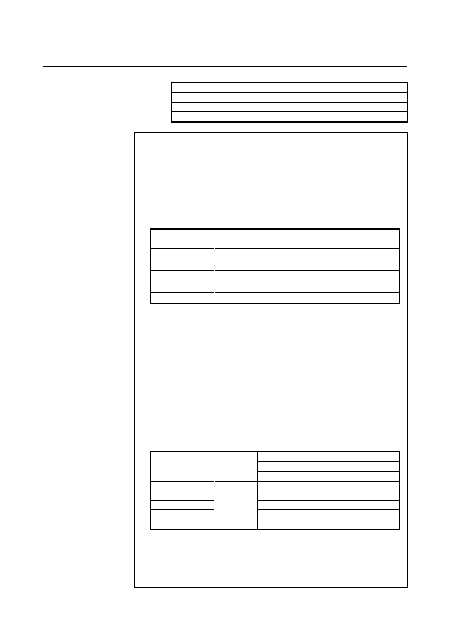
Increment system
Linear axis
(metric input)
Linear axis
(inch input)
Rotation axis
IS-A 2 3 2
IS-B 3 4 3
IS-C 4 5 4
IS-D 5 6 5
IS-E 6 7 6
When bit 7 (IPR) of parameter No. 1004 is set to 1, the above
values from which 1 is subtracted are used. When the
increment system for an axis is IS-A, however, the setting of
bit 7 (IPR) of parameter No. 1004 is not effective.
When calculator-type decimal notation for each axis is used
(bit 0 (ADX) of parameter No. 3455 is set to 1), the number of
decimal places is 0. When bit 7 (EAP) of parameter No. 3452
is set to 1, however, calculator-type decimal notation is not
effective and the number of decimal places is determined as
listed in the above table.
4
γ
is determined according to the increment system for the
reference axis (axis specified with parameter No. 1031) as
listed in the following table. (When bit 7 (BDX) of parameter
No. 3450 is set to 1,
γ
is also determined in the same way.)
AUP(3450#0) = 1
AUX (No.3405#0) = 0 AUX (No.3405#0) = 1
Increment system
for the reference
axis
AUP
(No.3450#0)
= 0
Metric Inch Metric Inch
IS-A 2
2
3
IS-B 3
3
4
IS-C 4
4
5
IS-D 5
5
6
IS-E
0
6 6
7
5 When bit 1 (FR3) of parameter No. 1405 is 1, the values in the
table need to be incremented by 1.
6 When calculator-type decimal notation is used (bit 0 (DPI) of
parameter No. 3401 is set to 1), the number of decimal places
is 0.