FANUC Series 30i/300i/300is-MODEL A. Machining Center System. User's manual - page 39
 

  Index      Manuals     FANUC Series 30i/300i/300is-MODEL A. Machining Center System. User's manual (B-63944EN/03)


Search            copyright infringement  


Content      ..     37      38      39      40     ..


FANUC Series 30i/300i/300is-MODEL A. Machining Center System. User's manual - page 39


10.TOOL FUNCTION (T FUNCTION)

 PROGRAMMING 

B-63944EN/03


- 268 - 

Example 

Example of setting tool offset memory A 

G10L77P3; 

Set tool management data screen display 
customization 

N1 R1; 

Set No. as number 1 

N2 R2; 

Set TYPE-NO. as number 2 

N3 R3; 

Set MG as number 3 

N4 R4; 

Set POT as number 4 

N5 R5; 

Set T-INFORMATION as number 5 

N6 R6; 

Set L-COUNT as number 6 

N7 R7; 

Set MAX-LIFE as number 7 

N8 R8; 

Set NOTICE-L as number 8 

N9 R9; 

Set L-STATE as number 9 

N10 R11; 

Set F (Feedrate) as number 10 

N11 R21;   

Set D as number 11 

N12 R22; 

Set OFFSET-M as number 12 

N13 R80; 

Set CUSTOM 0 as number 13 

N14 R81; 

Set CUSTOM 1 as number 14 

N15 R-1; 

End 

G11; 

Cancel the setting mode 

 
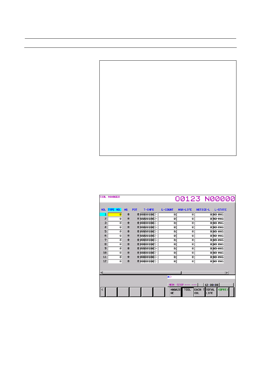
On the tool management data screen, the first page displays "No., 
Type Number, MG, Pot, Tool Information, Life Counter, Maximum 
Life, Noticed Life, and Life State". 
The second page displays "F (Feedrate), D (Cutter Compensation 
Number), Tool Offset-M, Customize Data 0, and Customize Data 1". 


Example 1:  Page 1 


B-63944EN/03

 PROGRAMMING 

10.TOOL FUNCTION (T FUNCTION)


- 269 - 


Example 1:  Page 2 


NOTE 

1  This setting is enabled when bit 0 (TDC) of 

parameter No. 13201 is set to 1. 

2  Up to 20 pages can be set. 
3  Be sure to specify an end. 
4  If an item that requires the corresponding option is 

specified without specifying the option, the item is 
displayed as a blank field. 

5  No items after an end are displayed. 

(Example) In the case of N1 

 R1 (No.), N2 

 R2 

(Type Number), N 3 

 R3 (MG), N4 


R-1 (End), N5 

 R4 (Pot), only the items 

"No., Type Number, and MG" are 
displayed on the screen. 

6  If G10 L77 P3 is specified, the setting immediately 

before is initialized. 

7  If an invalid value is set in R (tool management data 

display item), a blank field is displayed. 


10.TOOL FUNCTION (T FUNCTION)

 PROGRAMMING 

B-63944EN/03


- 270 - 

10.3.2 

Setting of Spindle Position / Standby Position Display 

 
In MG on the tool management data screen, a spindle position or 
standby position is displayed as a number such as 11, 12, and 13.   
With the spindle position/standby position display setting function, 
three arbitrary characters can be displayed using the G10 format. 


Format 

G10L77P4; 
N_; 
P_R_; 
G11; 

N_: Spindle position/standby position setting 
P_: Character number 
R_: Character code 


Explanation 
  - Spindle position/standby position setting (N_) 

Specify a spindle position or standby position to be renamed.  The 
table below indicates the values to be specified. 
 

Spindle position 


First Second Third Fourth 

1st 

path 111 112 113 114 

2nd 

path 

211 212 213 214 

3rd 

path 

311 312 313 314 

4th 

path 411 412 413 414 

5th 

path 511 512 513 514 

6th 

path 611 612 613 614 

7th 

path 711 712 713 714 

8th 

path 811 812 813 814 

9th 

path 911 912 913 914 

10th 

path 1011 1012 1013 1014 


Standby position


First Second Third Fourth 

1st 

path 121 122 123 124 

2nd 

path 

221 222 223 224 

3rd 

path 

321 322 323 324 

4th 

path 421 422 423 424 

5th 

path 521 522 523 524 

6th 

path 621 622 623 624 

7th 

path 721 722 723 724 

8th 

path 821 822 823 824 

9th 

path 921 922 923 924 

10th 

path 1021 1022 1023 1024 


B-63944EN/03

 PROGRAMMING 

10.TOOL FUNCTION (T FUNCTION)


- 271 - 

  - Character number (P_) 

Specify a character number (1 to 3).  Up to three characters are 
displayed.    If a character string to be specified is shorter than three 
characters, specify 0 in the leading blank character position(s).  A 
character string immediately before 0 is displayed. 
 

  - Character code (R_) 

Set the name of a spindle position/standby position by using a 
character code (ASCII code or Shift JIS code). 

For a character code, use ASCII code or Shift JIS code. 

No character code data check is made. 


Example 

When spindle 1 is named "SP1", and standby 1 is named "WT1" 

G10L77P4; 

Set spindle position/standby position 

N111; 

Specify spindle 1 

P1 R83; 

53h as ASCII code for "S" 

P2 R80; 

50h as ASCII code for "P" 

P3 R49; 

31h as ASCII code for "1" 

N121; 

Specify standby 1 

P1 R87; 

57h as ASCII code for "W" 

P2 R84; 

54h as ASCII code for "T" 

P3 R49; 

31h as ASCII code for "1" 

G11; 

Cancel the setting mode 

 
In the MG item on the tool management data screen, spindle 1 is 
displayed as "SP1", and standby 1 is displayed as "WT1". 


NOTE 


Data registered becomes effective after the screen 
display is switched to the tool management screen. 


10.TOOL FUNCTION (T FUNCTION)

 PROGRAMMING 

B-63944EN/03


- 272 - 

10.3.3 

Input of Customize Data with the Decimal Point 

 
With the function for input of customize data with the decimal point, 
the number of decimal places can be set using the G10 format for each 
customize data item (customize data 1, ..., 40) to enable data input 
with the decimal point. 
 

Format 

G10L77P5; 
N_R_; 
G11; 

N_: Customize data number 
R_: Decimal point position 


Explanation 
  - Customize data number (N_) 

A value of 1 to 4 can be specified for N. 

When tool management function customize data extension (5 to 
20) is available, a value of 1 to 20 can be specified. 

When tool management function customize data extension (5 to 
40) is available, a value of 1 to 40 can be specified. 


  - Decimal point position (R_) 

Specify a decimal point position (0 to 7).    When 0 is set, the number 
of decimal places of customize data cannot be input. 
 

NOTE 

1  If G10 L77 P5 is terminated normally, the power 

must be turned off before operation is continued. 

2  The setting becomes effective after the power is 

turned off then back on. 

3  When the number of decimal places is set for 

customize data, the number of decimal places can 
be input only through the MDI keys. 

4  To set the number of decimal places for customize 

data 5 to 20, the customize data extension (5 to 20) 
option for the tool management function or the 
customize data extension (5 to 40) option for the 
tool management function is required. 

5  To set the number of decimal places for customize 

data 21 to 40, the customize data extension (5 to 
40) option for the tool management function is 
required. 


B-63944EN/03

 PROGRAMMING 

10.TOOL FUNCTION (T FUNCTION)


- 273 - 

Example 1 

When customize data 1 and customize data 2 are input with three 
decimal places 

G10L77P5; 

Set the number of decimal places for 
customize data 

N1 R3; 

Set the number of decimal places to 3 for 
customize data 1 

N2 R3; 

Set the number of decimal places to 3 for 
customize data 2 

G11; 

Cancel the setting mode 


  - Use in the G10 format 

Between G10 and G11, the decimal point cannot be specified at any 
address.  So, if decimal point input for customize data is enabled 
with this function, a G10 L75/L76/L77 command using a custom 
macro variable (#8431 to #8450) reads and sets the value of the 
integer part. 
 

10.TOOL FUNCTION (T FUNCTION)

 PROGRAMMING 

B-63944EN/03


- 274 - 

Example 2 

(Example 1) 

Condition: 
 

"3" is set as the decimal point position of customize data 1. 


"1" is set as the decimal point position of customize data 2. 

Operation: 
 

Data is transferred from customize data 1 to customize data 
2 by using a custom macro variable. 


G10L77P5; <1> 

Set 

customize 

data decimal point position 

N1 R3; 

<2>  Set 3 as decimal point position of customize data 1 

N2 R1; 

<3>  Set 1 as decimal point position of customize data 2 

G11; 

<4>  Cancel the setting mode 

;  
G10 L75 P1; 

<5>  Register tool management data 

N01; 

<6>  Register with No. 1 

P1 R12345; 

<7>  Set ”12.345” for customize data 1 

P2 R#8431; 

<8>  Set ”1.2” for customize data 2 

G11; 

<9>  Cancel the setting mode 


In Example 1, customize data 1 is directly set in customize data 2 
by using a custom macro variable. 


Customize data 1 holds "12.345".    In step <8>, only the integer 
part is read and processed as "P2 R12". 


So, "1.2" is set in customize data 2. 

 
(Example 2) 

Condition: 
 

"3" is set as the decimal point position of customize data 1. 


"1" is set as the decimal point position of customize data 2. 

Operation: 
 

By using the custom macro variable of customize data 1, the 
data is transferred to customize data 2 after being multiplied 
by 1000. 


G10L77P5; <1> 

Set 

customize 

data decimal point position 

N1 R3; 

<2>  Set 3 as decimal point position of customize data 1

N2 R1; 

<3>  Set 1 as decimal point position of customize data 2

G11; 

<4>  Cancel the setting mode 

;  
G10 L75 P1; 

<5>  Register tool management data 

N01; 

<6>  Register with No. 1 

P1 R12345; 

<7>  Set ”12.345” for customize data 1 

P2 R[#8431*1000];

<8>  Set ”1234.5” for customize data 2 

G11; 

<9>  Cancel the setting mode 


In Example 2, customize data 1 is directly set in customize data 2 
by using a custom macro variable. 


Customize data 1 holds "12.345".  In step <8>, the data is 
multiplied by 1000 to eliminate the fractional part. 


So, this command is equivalent to "P2 R12345", so that "1234.5" 
is set in customize data 2. 

B-63944EN/03

 PROGRAMMING 

10.TOOL FUNCTION (T FUNCTION)


- 275 - 

10.3.4 

Protection of Various Tool Information Items with the KEY 

Signal 

 
When tool management data is in the edit state, various information 
items can be modified.    By setting bit 0 of parameter No. 13204 to 1, 
tool management data can be protected with the KEY signal so that 
various information items are not registered, modified, and deleted. 
 

10.3.5 

Selection of a Tool Life Count Period 

 
A tool life count period can be chosen between 1 sec and 8 msec on a 
tool-by-tool basis. 
 

  - Tool life count period selection 

Bit 5 of tool information is used to make a life count period selection. 
 

Item Description 

Data length 

1 byte (flag data) 

#5 

REV 

0: A life count period of 1 sec is used. 
1: A life count period of 8 msec is used. 

 
Range of count is as follows. 
1sec:  

0 to 3,599,999 seconds (999 hours 59 minutes 59 seconds) 

8msec:  0 to 3,599,992 ms (59 minutes 59 seconds 992 milliseconds) 
 

NOTE 


This function is valid when the tool information TIM 
(#1) is set to 1. 


Content      ..     37      38      39      40     ..