FANUC Series 0i-MODEL F Plus. CONNECTION MANUAL (FUNCTION) - page 319
 

  Index      Manuals     FANUC Series 0i-MODEL F Plus. CONNECTION MANUAL (FUNCTION) B-64693EN-1/01


Search            copyright infringement  


Content      ..     317      318      319      320     ..


FANUC Series 0i-MODEL F Plus. CONNECTION MANUAL (FUNCTION) - page 319


16. PMC CONTROL FUNCTION


B-64693EN-1/01


- 2506 - 


Path 2


Path 1


PMC 

CNC 

Group 2 command


Group 1 command


Group 2


Group 1


DI / DO 

First axis control


Second axis control


Third axis control


Fourth axis control


Fig. 16.1.1 (b) Example of correct relationships between groups and axes 

 
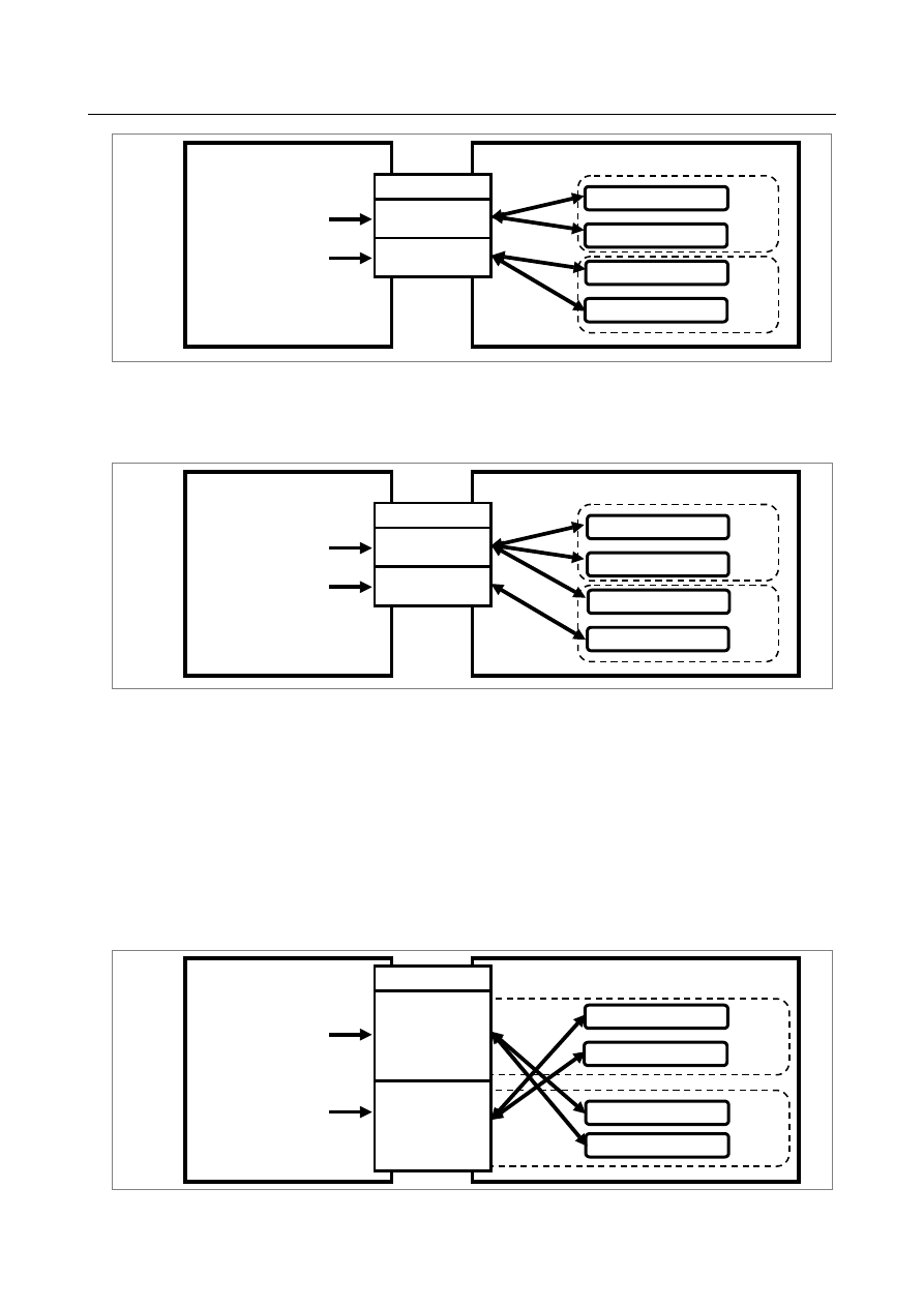
In  Fig.  16.1.1  (c), " Example of incorrect relationships between groups and axes", the first and second 
axes specified with group 1 belong to path 1, but the third axis specified with group 1 belongs to path 2, 
so that an intended operation is not performed. 


Path 2


Path 1


PMC 

CNC 

Group 2 command


Group 1 command


Group 2


Group 1


DI / DO 

First axis control


Second axis control


Third axis control


Fourth axis control


Fig. 16.1.1 (c) Example of incorrect relationships between groups and axes 

 
As mentioned earlier, in PMC axis control, group-by-group signal addresses are allocated in the signal 
area of each path, but PMC axis control and multi-path control are independent of each other. 
So, from the path to which group-by-group signal addresses are allocated, commands can be issued to 
axes that belong to another path. In this case, however, check that the target axes belong to the same path. 
 
In  Fig.  16.1.1  (d), “Commands to different paths”, the group-by-group signal addresses of group 1 are 
allocated to path 1, and the group-by-group signal addresses of group 5 are allocated to path 2. (See Table 
16.1.1 (b), “Allocation of group-by-group signals”.) 
 
Group 1 can issue commands to the axes that belong to path 2. Similarly, group 5 can issue commands to 
the axes that belong to path 1. 


Path 2


Path 1


PMC 

CNC 

Group 5 command


Group 1 command


Group 5 

(Signal addresses are 

allocated to path 2.)


DI / DO 

First axis control


Third axis control


Group 1 

(Signal addresses are 

allocated to path 1.)


Second axis control


Fourth axis control


Fig. 16.1.1 (d) Commands to different paths 

B-64693EN-1/01


16. PMC CONTROL FUNCTION


- 2507 - 

  - 

Relationships between paths and groups (path-by-path signals, path-by-path 
parameters) 

Path-by-path signal addresses are allocated in the signal area of each path. (See Table  16.1.1  (c), 
“Example of Path-by-path signal (PMC axis control override signal) allocation”.) 
However, PMC axis control and multi-path control are independent of each other. 
The path-by-path direct signal (X) is described later. 
 

NOTE 


The number of available groups depends on the number of NC path or type of 
PMC. 
Generally, the maximum number of available groups equals the number of NC 
paths multiplied by 4. 


Table 16.1.1 (c) Example of Path-by-path signal (PMC axis control override signal) allocation 

Group-by-group signal 

Input signal (G) address 

Output signal (F) address 

Group 1 

G0150.0,1,6,7, G0151 

F0129.5,7 

Group 2 

G0150.0,1,6,7, G0151 

F0129.5,7 

Group 3 

G0150.0,1,6,7, G0151 

F0129.5,7 

Group 4 

G0150.0,1,6,7, G0151 

F0129.5,7 

Group 5 

G1150.0,1,6,7, G1151 

F1129.5,7 

Group 6 

G1150.0,1,6,7, G1151 

F1129.5,7 

Group 7 

G1150.0,1,6,7, G1151 

F1129.5,7 

Group 8 

G1150.0,1,6,7, G1151 

F1129.5,7 

Group 9 

G2150.0,1,6,7, G2151 

F2129.5,7 

Group 10 

G2150.0,1,6,7, G2151 

F2129.5,7 

Group 11 

G2150.0,1,6,7, G2151 

F2129.5,7 

Group 12 

G2150.0,1,6,7, G2151 

F2129.5,7 

Group 13 

G3150.0,1,6,7, G3151 

F3129.5,7 

Group 14 

G3150.0,1,6,7, G3151 

F3129.5,7 

Group 15 

G3150.0,1,6,7, G3151 

F3129.5,7 

Group 16 

G3150.0,1,6,7, G3151 

F3129.5,7 

 
A path-by-path signal is input/output to and from a signal of the path to which the group belongs (for 
example, path 1 when a command is issued from group 1). No path-by-path signal is input/output to and 
from the path to which the axis assigned to the group belongs. 
 
In Fig. 16.1.1 (e), "Relationships between paths and groups for path-by-path signals (G, F)", for example, 
the signal EBUFB#2 (described later) input from group 5 (whose signal addresses are allocated to path 2) 
is output to EOV#2 (path-by-path signal described later) of path 2 to which group 5 addresses are 
allocated. 
EBUFB#2 is not output to EOV#1 of path 1, to which the first axis assigned to group 5 belongs. 

16. PMC CONTROL FUNCTION


B-64693EN-1/01


- 2508 - 


Path 2


Path 1


PMC 

CNC 

Group 5 command


Group 5 

(Signal 

addresses are 

allocated to path 

2.)


DI / DO 

First axis control


Second axis control


Group 1 

(Signal 

addresses are 

allocated to path 

1.) 

Path-by-path signal


EOV#1


Path-by-path signal


EOV#2


Fig. 16.1.1 (e) Relationships between paths and groups for path-by-path signals (G, F) 


Restrictions on the number of groups 

Basically,  PMC  axis control and multi-path control are independent of each other, but there are the 
following restrictions. 
 
1. 

When  PMC/L  is used as PMC, the groups up to group 8 can be used. Group 9 and later groups 
cannot be used. 

 
2. 

When PMC control is performed with more than four times as many groups as the number of NC 
paths, the signals shown in (A) and (B) below cannot be used for the excess paths and groups. 
To use feedrate override signals, etc., set bit 2 (OVE) of parameter No. 8001 to 1. 
(A)  Path-by-path signals common to all groups 

Fx129.7   

*EAXSL 

Fx129.5   

EOV0 

(B)  Signals same as the CNC 

Gx012 


*FV0-*FV7 

Gx006.4   

OVC 

Gx014.0,1 

ROV1,2 

Gx046.7   

DRN 

Gx019.7   

RT 

 
For example, when the number of NC paths is 2, the signals in (A) and (B) can be used by the groups up 
to group 8. 
 
The restrictions on the number of NC paths, available (A) signals, and available (B) signals are shown 
Table 16.1.1 (d). 

Table 16.1.1 (d) 

Number of NC paths 

Available (A) signals 

Available (B) signals 

F129.5,7 

(B) signals in the range from G0 to G0767 

F129.5,7,…, F1129.5,7 

(B) signals in the range from G0 to G1767 

F129.5,7,…, F2129.5,7 

(B) signals in the range from G0 to G2767 

F129.5,7,…, F3129.5,7 

(B) signals in the range from G0 to G3767 


B-64693EN-1/01


16. PMC CONTROL FUNCTION


- 2509 - 

  - 

Direct signal, path-by-path parameter 

The direct signal (X) and path-by-path parameter differ from the path-by-path signals (G, F). 
The direct signals and parameter values set for the paths to which all axes related to a group belong are 
valid. 
The direct signals and parameter values are irrelevant to values set for the path to which a group belongs. 
 
In Fig. 16.1.1 (f), "Relationships between paths and groups for the direct signal (X)", when a command is 
issued from group 5 to an axis of path 1, the valid direct signal ESKIP (described later) is ESKIP#1 of 
path 1. The signal ESKIP#2 of path 2 is invalid. 


Path 2


Path 1


PMC 

CNC 

Group 5 command


Signal address 

area of path 2 

(Group 5)


DI / DO 

First axis control


Second axis control


Signal address 

area of path 1


Direct signal 

ESKIP#2


Direct signal 

ESKIP#1


Fig. 16.1.1 (f) Relationships between paths and groups for the direct signal (X) 

 
In  Fig.  16.1.1  (g), "Relationships between path-by-path parameters and groups", when a command is 
issued from group 5 to path 1, the setting value of 0 with bit 2 (OVE) of the path-by-path parameter No. 
8001 for path 1 is valid. 


Path 2


Path 1


PMC 

CNC 

Group 5 command


Signal address area of 

path 2 (group 5)


DI / DO 

First axis control


Second axis control


Parameter for path 1 

8001#2=0


Parameter for path 2 

8001#2=1


Fig. 16.1.1 (g) Relationships between path-by-path parameters and groups 


  - 

Relationships between axes and paths (axis-by-axis signals, axis-by-axis 
parameters) 

The specifications of the axis-by-axis signals and axis-by-axis parameters associated with the 
relationships between paths and axes are the same as the NC specifications. 
Signals and parameters set for an axis are valid for the axis, and are not affected by groups. 
 
PMC axis control consists of groups, axes, and paths. 
 
Among the three relationships, that is, the group-axis, path-group, and path-axis relationships, the two 
relationships other than the path-axis relationship represent a concept specific to PMC axis control. 
 

16. PMC CONTROL FUNCTION


B-64693EN-1/01


- 2510 - 

  CAUTION 

1  PMC axis control cannot be used to an axis under the axis synchronous control. 

Cancel axis synchronous control before starting PMC axis command. 

2  PMC axis control cannot be used to an axis under synchronous slave axis of 

synchronous/composite control. Cancel synchronous control before starting 
PMC axis command in slave axis. 

3  Each axes cannot execute another PMC axis command by assigning two or 

more axes to the same group. Assign the axes to another groups, and command 
to each group. 


Basic procedure 

(1)  In parameter No. 8010, set one of groups 1 to 16 for use with each axis to be used. 
 

When


movements


are


made


along


multiple


axes


for


synchronization by using one group, ensure that the 

feedrate-related parameters (rapid traverse, acceleration/deceleration time constant, diameter/ radius 
specification, linear axis/rotation axis, and so forth) must be set to the same conditions. 


When assigning multiple axes to one group, check that all axes that belong to the group are in the 
same path. 

(2)  To detach from CNC control and to enable direct PMC axis control, set each control axis selection 

signal (EAX1 to EAX8) bit, that corresponds to an axis to be controlled, to “1“. 

(3)  Determine the operation. 

The axis control command signals (EC0g to EC6g) specify the type of operation. The axis control 
feedrate signals (EIF0g to EIF15g) specify the feedrate. The axis control data signals (EID0g to 
EID31g) specify the moving distance and other data. 


These signals, together with block stop prohibition signal EMSBKg (described later), determine one 
complete operation, which is tantamount to one block command  executed during CNC-controlled 
automatic operation. These signals may be collectively called the axis control block data signals. 
(Refer to Table 16.1.1 (e), “List of signals determining data, tantamount to one block for PMC axis 
control”.) 


Table 16.1.1 (e) List of signals determining data, tantamount to one block for PMC axis control 

Generic name 

Signal name 

Symbol 

Data type 

Axis control block data 

signals 

Block stop prohibition signal 

EMSBKg 

Bit 

Axis control command signal 

EC0g to EC6g 

Byte 

Axis control feedrate signal 

EIF0g to EIF15g 

Word 

Axis control data signal 

EID0g to EID31g 

2-word 

 
(4)  When the data governing a complete operation (one block) is determined, reverse the logical state of 

the axis control command read signal EBUFg (i.e., from “0“ to “1“ or vice versa). Note that, for this 
to occur, axis control command read completion signal EBSYg must be in the same logical state as 
EBUFg. 

(5)  The CNC is capable of storing axis control functions from the PMC in its buffer so that multiple 

operations can be performed in series, under the control of the PMC. This allows the CNC to accept 
a new  command block from the PMC during the execution of another block if the buffer has free 
space. 


The Fig. 16.1.1 (h), "Buffering under PMC axis control" illustrates an example in which command 
[1] is being executed, commands [2] and [3] are stored in the buffers, and command [4] has been 
issued (the axis control block data signal is set).   

B-64693EN-1/01


16. PMC CONTROL FUNCTION


- 2511 - 


Block 1


Block 2


Block 3


Block 4


Block 5


Block n


 : 

PMC Commands


Setting of the axis 
control block data signal


CNC's buffers


[1]


[2]


[3]


Executing buffer


 : 


Waiting buffer


Input buffer


[4]


Command [1]


Command [2]


Command [3]


Command [4]


Command [5]


Fig. 16.1.1 (h) Buffering under PMC axis control 

 
When the execution of command [1] is completed: 
  Command [2] is transferred from the waiting buffer to the executing buffer; 
  Command [3] is transferred from the input buffer to the waiting buffer;   
  and 
  Command [4] is transferred to the input buffer as the command block (axis control block data signal). 
After the reception of command [4] by the input buffer, the PMC can issue command [5] to the CNC (the 
axis control block data signal is set). 
The timing chart for the command operation is shown below. (Fig. 16.1.1 (i), "Timing chart of command 
operation") 


Command block


[1]  


[2]  


[3]  


[4]  


[5]  


(Input) 


EBUFg 


(Input) 


(1)  


(2)  


(3)  


(4)  


(5) 

Uncommandable 


EBSYg 


(Output) 


Input buffer 


[3]  


[4]  


Waiting buffer 


[2]  


[3]  


Executing buffer 


[1]  


[2]  


Beginning 
of execution 


End of 
execution 


Beginning 
of execution 


Fig. 16.1.1 (i) Timing chart of command operation 

 
(1), (2), (3), (4), (5) : A new block cannot be issued during these intervals (while EBUFg and EBSYg are 
in different logical states). In interval (4), the buffer is in the "full" state. 
 

16. PMC CONTROL FUNCTION


B-64693EN-1/01


- 2512 - 

The status of the CNC buffer can be determined by the exclusive OR of the axis control command read 
signal EBUFg, input from the PMC, and axis control command read completion signal EBSYg, output 
from the CNC. (Table 16.1.1 (f), "Buffering status in PMC axis control") 
 

Table 16.1.1 (f) Buffering status in PMC axis control 

EBUFg 

EBSYg 

Exclusive OR 

(XOR) 

CNC buffer status 

The previous block has already been read into the CNC buffer. The 
PMC can issue the next block. 

The previous block has not yet been read completely. It is just being 
read or buffer is in the "full" state, and waiting for the CNC buffer to 
become available. Do not issue the next block, nor reverse the 
logical state of EBUFg. Reversing the EBUFg state invalidates any 
block that has been already issued. 

 
(6)  Repeat steps (3) and (4) until all the blocks have been issued. 
 

When the final block has been issued and other command is unnecessary, set control axis selection 
signals EAX1 to EAX8 to “0“. Before setting these signals to “0“, however, check that the blocks 
stored in the CNC's input, waiting, and executing buffers have all been executed. Setting the signals 
to “0“ while a block is being executed, or while a block remains in any of these buffers, results in the 
issue of a P/S alarm. This alarm PS0139, “CANNOT CHANGE PMC CONTROL AXIS” suspends 
the current block execution and invalidates the blocks stored in the input and waiting buffers. 


To ensure no block is being executed, or that there are no blocks remaining in the input or waiting 
buffer, check that control axis selection status signal *EAXSL is set to “0“. 


For those axes that are always subject to PMC control without switching the management between 
CNC and PMC, such as those controlling turrets, pallets, and ATCs, ensure that the EAX1 to EAX8 
signals are always set to “1“. There is no need to set these signals to “0“ after  issuing commands 
from the PMC to the CNC. When all command blocks have been executed (there are no blocks 
remaining to be executed), the CNC automatically stops execution. 

(7)  When control axis selection signals EAX1 to EAX8 are set from “1“ to “0“, control is returned to the 

CNC. 


Command 

Overview of commands   

As described in step (3) in the basic procedure, one PMC axis control command block is represented by 
the axis control block data signals. 


PMC axis control enables the commands indicated in Table 16.1.1 (g), “Command list” to be specified. 
 
In Table 16.1.1 (g), "Command list": 
"Command" represents the axis control command signals (EC0g to EC6g). 
"Data 1" represents the axis control feedrate signals (EIF0g to EIF15g). 
"Data 2" represents the axis control data signals (EID0g to EID31g). 
 

B-64693EN-1/01


16. PMC CONTROL FUNCTION


- 2513 - 

Table 16.1.1 (g) Command list 

No.  Command 

Operation 

Data 1 

Data 2 

Description 

(1) 

00h 

Rapid traverse 

Rapid 

traverse rate 

(NOTE) 

Total moving 

distance 

The same operation as “G00” of the CNC 
is performed. 

(2) 

01h 

Cutting feed - feed 

per minute 

Cutting 

feedrate 

Total moving 

distance 

The same operation as “G94 G01” of the 
CNC is performed. 

(3) 

02h 

Cutting feed - feed 

per revolution 

Feedrate per 

revolution 

Total moving 

distance 

The same operation as “G95 G01” of the 
CNC is performed. 

(4) 

03h 

Skip - feed per 

minute 

Cutting 

feedrate 

Total moving 

distance 

The same operation as “G31 G01” of the 
CNC is performed. 

(5) 

04h 

Dwell 

--- 

Dwell time 

The same operation as “G04” of the CNC 
is performed. 

(6) 

05h 

Reference position 

return 

--- 

--- 

After a rapid traverse movement is made 
in the reference position return direction 
set by bit 5 (ZMIx) of parameter No. 1006, 
the same operation as manual reference 
position return of the CNC is performed. 

(7) 

06h 

Continuous feed 

Continuous 

feedrate 

Feed direction 

(EID31g only) 

A continuous feed operation is performed 
along a controlled axis in a certain 
direction. 
The same operation as continuous feed in 
the JOG mode of the CNC is performed. 

(8) 

07h 

First reference 

position return 

Rapid 

traverse rate 

(NOTE) 

--- 

The same operation as reference position 
return from an intermediate position done 
with “G28” of the CNC is performed. 

(9) 

08h 

Second reference 

position return 

Rapid 

traverse rate 

(NOTE) 

--- 

The same operation as reference position 
return from an intermediate position done 
with “G30 P2” of the CNC is performed. 

(10) 

09h 

Third reference 

position return 

Rapid 

traverse rate 

(NOTE) 

--- 

The same operation as reference position 
return from an intermediate position done 
with ”G30 P3” of the CNC is performed. 

(11) 

0Ah 

Fourth reference 

position return 

Rapid 

traverse rate 

(NOTE) 

--- 

The same operation as reference position 
return from an intermediate position done 
with G30 P4” the CNC is performed. 

(12) 

0Bh 

External pulse 

synchronization - 

position coder 

Pulse weight 

--- 

Synchronous operation with the position 
coder is performed. 

(13) 

0Dh 

External pulse 

synchronization - 

first manual handle 

Pulse weight 

--- 

Synchronous operation with the first 
manual handle is performed. 

(14) 

0Eh 

External pulse 

synchronization - 

second manual 

handle 

Pulse weight 

--- 

Synchronous operation with the second 
manual handle is performed. 

(15) 

0Fh 

External pulse 

synchronization - 

third manual handle 

Pulse weight 

--- 

Synchronous operation with the third 
manual handle is performed. 

(16) 

10h 

Speed command 

Speed 

specified by 

speed 

command 

--- 

Continuous feed operation based on a 
speed command is performed. 

(17) 

11h 

Torque control 

Maximum 

feedrate 

Torque data 

Continuous feed operation based on 
torque control is performed. 

(18) 

12h 

Auxiliary function 1 

--- 

Auxiliary 

function code 

The same operation as an auxiliary 
function of the CNC is performed. 


Content      ..     317      318      319      320     ..