FANUC Series 0i-MODEL F Plus. CONNECTION MANUAL (FUNCTION) - page 249
 

  Index      Manuals     FANUC Series 0i-MODEL F Plus. CONNECTION MANUAL (FUNCTION) B-64693EN-1/01


Search            copyright infringement  


Content      ..     247      248      249      250     ..


FANUC Series 0i-MODEL F Plus. CONNECTION MANUAL (FUNCTION) - page 249


11. TOOL FUNCTIONS


B-64693EN-1/01


- 1946 - 


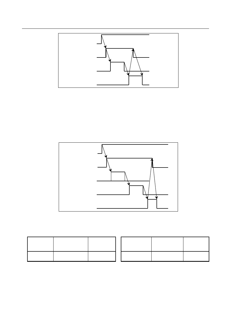
T code output 
<Fn026-Fn029> 

Tool function strobe 
signal TF<Fn007.3> 

PMC window function 
code 329 

Completion signal 
FIN<Gn004.3> 


  N80 M06; 

(1)  In response to the M06 command, M code binary value 0006 is output to PMC F addresses <Fn010 

to Fn013> and the MF signal is output to <Fn007.0>. 

(2)  The machine performs a tool change operation, and moves the tool from the standby position to 

spindle position. 

(3)  With the PMC window (function code 329), the tools at the standby position and spindle position in 

the cartridge management table are changed. 

(4)  The CNC regards the tool moved to the spindle position (cartridge number 11) by the PMC window 

(function code 329) as a new tool targeted for tool life management. 

(5)  The miscellaneous function completion signal is sent from the PMC to CNC. 


M code output 
<Fn010-Fn013> 

Miscellaneous 
function strobe signal 
MF<Fn007.0> 

PMC window function 
code 329 

Completion signal 
FIN<Gn004.3> 

Tool 
change 


  - 

When a tool with shortest life is attached at spindle position 

An operation example in which a T code command is issued when a tool with the shortest life is already 
attached at the spindle position is explained below. 
 

Spindle 

name 

Cartridge No. 

(Spindle No.) 

Data No. 


Standby 

position name 

Cartridge No. 

(Standby 

position No.) 

Data No. 

Spindle 

position 

11 


Standby position   

21 


  N10 T11111111 ; 

(1)  From the tools with tool type number 11111111, a tool with the shortest life is searched for. 
(2)  Since the tool with the shortest life is the tool at the spindle position (tool management data number 

1), binary value 0011 is output to PMC addresses <Fn026 to Fn027>. At the addresses indicating the 
pot number <Fn028 to Fn029>, binary value 0000 is output. 

(3)  Tool function strobe signal TF is output to the PMC. 
(4)  Since a tool change operation is not needed, the PMC sends completion signal FIN to the CNC. 

B-64693EN-1/01


11. TOOL FUNCTIONS


- 1947 - 


T code output 
<Fn026-Fn029> 

Tool function strobe 
signal TF<Fn007.3> 

Completion signal 
FIN<Gn004.3> 


  N80 M06; 

(1)  M code binary value 6 is output to the PMC addresses <Fn010 to Fn013>. 
(2)  Miscellaneous function strobe signal MF <Fn007.0> is output to the PMC. 
(3)  Since a tool change operation is not needed, the PMC sends completion signal FIN to the CNC. 
(4)  The CNC starts counting the tool life  of the tool held at the spindle position. For the type for 

counting the number of use times, the life count is incremented by one. 


M code output 
<Fn010-Fn013> 

Auxiliary function strobe 
signal MF<Fn007.0> 

Completion signal 
FIN<Gn004.3> 


  - 

When the life of the tool being used has expired 

An operation example when the tool life of the tool being used (the tool at the spindle position) has 
expired is explained below. 

Tool management data 

Data 

No. 

Tool type 

No. (T) 

Tool life 

counter 

Maximum 

tool life value 

Tool life 

status 

Tool 

information 

Tool length 

compensation 

No. (H) 

Cutter 

compensation 

No. (D) 

11111111 

999 

1000 

Not expired 

UNCR 

11111111 

1000 

Not expired 

UNCR 

11111111 

1000 

Not expired 

UNCR 


Cartridge management table 

No. 

Cartridge No. 

Pot No. 

Tool management data No. 

12 

29 

29 

30 

30 


Spindle management table                             Standby position table 

Spindle 

name 

Cartridge No. 

(Spindle No.) 

Data No. 


Standby 

position name 

Cartridge No. 

(Standby position No.) 

Data No. 

Spindle 

position 

11 


Standby position 

21 


  - 

Type for counting the number of use times 

When a life is counted by counting the number of use times, the life count is incremented by one each 
time M06 (or an M code for restarting tool life counting or T code) is specified. 
 

11. TOOL FUNCTIONS


B-64693EN-1/01


- 1948 - 


  N80 M06; 

(1)  M code binary value 6 is output to PMC addresses <Fn010 to Fn013>. 
(2)  Miscellaneous function strobe signal MF <Fn007.0> is output to the PMC. 
(3)  Since a tool change operation has already completed, no tool change operation is performed. 
(4)  The PMC sends miscellaneous function completion signal FIN to the CNC. 
(5)  The CNC increments the life count for the tool held at the spindle position (tool management data 

No. 1) by one. 

(6)  The life count reaches 1000 (the maximum tool life), so the tool life expires. 
(7)  The CNC changes the tool life status for tool management data number 1 to 3 (life has expired). 
(8)  The CNC searches for a tool that has the same tool type number and has remaining life. 


M code output 
<Fn010-Fn013> 

Auxiliary function 
strobe signal 
MF<F007.0> 

Completion signal 
FIN<Gn004.3> 


  N999 M30; 

(1)  When the lives of all tools having the same tool type number have expired, tool change signal TLCH 

<Fn064.0> is set to 

1

 immediately even during operation. 

(2)  After a change to a new tool, tool reset signal TLRST <Gn048.7> is set to 

1

(3)  Tool change signal TLCH <Fn064.0> is set to 

“0“


Tool change signal 
TLCH<Fn064.0> 

Tool reset signal 
TLRST<Gn048.7> 

Tool change 


  - 

Type for counting time 

Operations performed when a life is counted by counting time are explained below. 
Suppose that the tool management data is set as listed below. 
Also suppose that the cartridge management table is the same as for the type for counting the number of 
use times. 
 

Data No. 

Tool type 

No. (T) 

Tool life 

counter 

Maximum 

tool life 

value 

Tool life 

status 

Tool 

information 

Tool length 

compensation 

No. (H) 

Cutter 

compensation 

No. (D) 

11111111 

3300 

3600 

Not 

expired 

UNTR 


  - 

N200 G01 X100.0 F100.0 ; 

For the type for counting time, the time (in seconds) taken to execute such a cutting block is added to the 
counter value. 
 
(1)  The life count reaches 3600 seconds (the maximum tool life), and the tool life expires. 
(2)  The CNC changes the tool life status for tool management data number 1 to 3 (life has expired). 
(3)  The CNC searches for a tool that has the same tool type number and has a remaining life. 
(4)  Individual tool change signal TLCHI <Fn064.2> is set to 

1

B-64693EN-1/01


11. TOOL FUNCTIONS


- 1949 - 

(5)  When the lives of all tools having the same tool type number have expired, tool change signal TLCH 

<Fn064.0> is set to 

1

(6)  Even when the tool life has expired, machining is continued until the machining program ends. 


Tool change signal 
TLCH<Fn064.0> 

Tool reset signal 
TLRST<Gn048.7> 

Tool change   

Individual tool change 
signal 
TLCHI<Fn064.2> 

Individual tool reset 
signal 
TLRSTI<Gn048.6> 

Tool change   


NOTE 


Time is counted up while a cutting feed operation after the execution of M06 or a 
restart M code or T code is in progress. When the spindle is stopped or is 
rotating, the count-up operation is not performed. The target tools are the tools 
attached at the first to fourth spindle positions. When one of the following 
conditions is met, the count-up operation is not performed: 

1  The tool life status indicates the invalid state (0) or breakage (4). 
2  Even when a cutting feed is performed, the cutting feed is not regarded as 

being in progress. 
-  When the system is in the FIN wait state 
-  During in-position check 
-  When the cutting feed override is 0% 
-  When an interlock is provided 
-  When the system is in the spindle speed arrival wait state 

  (The above states can be confirmed from diagnosis data Nos. 000 to 013.) 

-  When a machine lock is provided 


  - 

When the tool being used is broken 

A tool breakage is detected by the machine and is posted to the CNC via the PMC. The PMC posts the 
tool breakage to the CNC in one of the following three methods: 

The tool life status is changed to 4 (tool breakage) by using the PMC window (function code 332) 

The tool life status is changed to 4 (tool breakage) by using the PMC window (function code 335). 

Tool skip signal TLSKP <Gn048.5> is set to 

1

 
The tool placed in the tool breakage state is excluded from the target tools for tool life management when 
the next and subsequent T codes are specified. 

11. TOOL FUNCTIONS


B-64693EN-1/01


- 1950 - 


Tool skip signal 
TLSKP<Gn048

.

5> 

Tool skip completion signal 
TLSKF<Fn315

.

0> 

Tool broken 


  - 

T code command for specifying a particular tool 

To specify a particular tool directly without allowing the CNC to select a tool, use the following format: 
 
M_ T_ ; 
 

NOTE 


A block for specifying the above command must not contain any other command. 


M_ M code set in parameter No. 13252 


T_   
 

If bit 0 (TCF) of parameter No. 13200 is 0: 
 

Upper 4 digits:  Cartridge number (output to <Fn026 to Fn027>) 


Lower 4 digits:  Pot number (output to <Fn028 to Fn029>) 


If the T code command is not longer than 4 digits, it is output to <Fn026 to Fn027> of the PMC on 
the assumption that the cartridge number is 1. 


To specify a spindle position or standby position, set the pot number to 0. 


Upper 4 digits: Cartridge number (11, 21) 
Lower 4 digits: 0001 


If bit 0 (TCF) of parameter No. 13200 is 1: 
 

Any number from 0 to 99,999,999 

 
If bit 0 (TCF) of parameter No. 13200 is 1 (outputting a T code directly to the output signal), the binary 
value of the specified T code is output to <Fn026 to Fn029> without modification. 
 

NOTE 


Pot numbers must not exceed 9999. 


  - 

Search by customize data 

If bit 6 (SWC) of parameter No. 13203 is 0, a tool with the shortest life is searched for. If SWC is 1, a 
tool whose customize data with an arbitrary number holds the smallest is searched for. When SWC is set 
to 1, the number of the customize data by which a search operation is to be made is set in parameter No. 
13260. When 3 is set in parameter No. 13260, the registered tools are searched to find a tool whose 
customize data 3 holds the smallest. If 0 is set in parameter No. 13260, a tool with the shortest life is 
searched for. 
 
The customize data by which a search operation is to be made ranges from 1 to 99,999,999. If a negative 
value is set, its absolute value is assumed. If 0 is set, the tool is regarded as an invalid tool and is excluded 
from the tools to be searched. 
 

B-64693EN-1/01


11. TOOL FUNCTIONS


- 1951 - 

  - 

Tool search order 

Tools having a tool type number (T) specified by a program are searched sequentially from tool 
management data number 1 while registered data contents are checked. The following shows how a 
search operation is made within the NC: 


Is tool management data valid (is bit 0 (RGS) of tool information set to 1)?


Is tool being edited?


Does tool type number (T) match with specified number? 

Is tool registered in cartridge (is cartridge number non-zero value)?


Is cartridge targeted for search (are bits 0 to 3 of parameter No. 13203 set to 0)?


Is tool registered at spindle position or standby position of another path?


Does tool life status indicate that tool management is not performed (0)?


Is tool excluded from management target a search target (is bit 4 (SEN) of tool information 1)?


Search end 

Does tool life status indicate that life expired (3)?


Does tool life status indicate tool breakage (4)?


Regard tool with smallest remaining life or customize data value as candidate. 
Bit 6 (SWC) of parameter No. 13203 (0:    Check remaining life, 1:    Check customize data)


Check of next tool?


Search end


Yes 

No 

No 

Yes 

Yes 

No 

Yes 

No 

Yes 

No 

No 

Yes 

Yes 

No 

No 

Yes 

No 

No 

Yes 

Yes 


  - 

System variables 

The following tool management data (Table  11.3.1  (c)) of the tool being used as a spindle after a tool 
change by M06 and the tool to be used next which is specified by a T code can be read through custom 
macro variables: 

11. TOOL FUNCTIONS


B-64693EN-1/01


- 1952 - 

Table 11.3.1 (c) 

Being used 

Item 

#8401 

Data number 

#8402 

Tool type number (T) 

#8403 

Tool life counter 

#8404 

Maximum tool life value 

#8405 

Tool notice life value 

#8406 

Tool life status 

#8407 

Customize data 0 (bit) 

#8408 

Tool information 

#8409 

Tool length compensation number (H) 

#8410 

Cutter compensation number (D) 

#8411 

Spindle speed (S) 

#8412 

Cutting feedrate (F) 

#8413 

Tool geometry compensation number (G) 

#8414 

Tool wear compensation number (W) 

#8431 

Customize data 1 

#8432 

Customize data 2 

#8433 

Customize data 3 

#8434 

Customize data 4 

#8435 

Customize data 5 

#8436 

Customize data 6 

#8437 

Customize data 7 

#8438 

Customize data 8 

#8439 

Customize data 9 

#8440 

Customize data 10 

#8441 

Customize data 11 

#8442 

Customize data 12 

#8443 

Customize data 13 

#8444 

Customize data 14 

#8445 

Customize data 15 

#8446 

Customize data 16 

#8447 

Customize data 17 

#8448 

Customize data 18 

#8449 

Customize data 19 

#8450 

Customize data 20 

#8451 

Customize data 21 

#8452 

Customize data 22 

#8453 

Customize data 23 

#8454 

Customize data 24 

#8455 

Customize data 25 

#8456 

Customize data 26 

#8457 

Customize data 27 

#8458 

Customize data 28 

#8459 

Customize data 29 

#8460 

Customize data 30 

#8461 

Customize data 31 

#8462 

Customize data 32 

#8463 

Customize data 33 

#8464 

Customize data 34 

#8465 

Customize data 35 

#8466 

Customize data 36 

#8467 

Customize data 37 

#8468 

Customize data 38 

#8469 

Customize data 39 

#8470 

Customize data 40 

For machining 
center systems 

For lathe 
systems 

B-64693EN-1/01


11. TOOL FUNCTIONS


- 1953 - 

 
When a cartridge number of a spindle position (11 to 14) or standby position (21 to 24) is specified in 
#8400, information about the corresponding position can be read. 
If the spindle position table or standby position table has an empty pot, <empty> is read from #8402 to 
#8470. 
Value 0 is read from #8401 (data number). 
Therefore, machining conditions registered in tool management data can be specified directly by coding, 
for example, D#8410, H#8409, S#8411, and F#8412 with a tool change macro (such as M06). Similarly, 
customize data can be referenced by a custom macro, and machining programs can be customized 
according to the tool used. 
 

  - 

Specifying a tool compensation number 

M


When parameter No. 13265 is 0, a compensation number registered as tool management data of a tool 
attached at a spindle position can be selected by specifying H99 or D99. 
(99 is treated as a special number, so 99 cannot be specified directly as a compensation number.) 
When other than 0 is set in parameter No. 13265, the number set in the parameter can be specified instead 
of 99. For example, if parameter No. 13265 is 3, specifying H3 specifies the tool length compensation 
number registered for the tool at the spindle position. 
 

T


When the tool management function is not used, a tool compensation number is specified also with a T 
code; when the tool management function is used, the T code is used only to specify a tool type number, 
so a tool compensation number must be specified with address D. 
Except the specifications for addresses, the specifications for the number of permissible digits (parameter 
No. 3032) and the number of digits consisting of a compensation number (parameter No. 5028), 
separation of geometry compensation numbers and wear compensation numbers (bit 1 (LGN) of 
parameter No. 5002), and so on are the same as for T. 
 
If parameter No. 13265 is set to 0, when a compensation number registered for a tool attached at a spindle 
position is specified, the specification format varies according to the number of digits as follows, which is 
the same as for conventional T: 
When the compensation number is 1 digit long: D9 
When the compensation number is 2 digits long: D99 
When the compensation number is 3 digits long: D999 
Because 9, 99, or 999 is treated as a special number, it cannot be specified directly as a compensation 
number. 
Unless parameter No. 13265 is set to 0, the number set in the parameter can be specified instead of 9, 99, 
or 999. When parameter No. 13265 is set to 3, specifying D3 specifies the tool geometry compensation 
number and tool wear compensation number registered for a tool attached at the spindle position. 


  Multi-path system 

Depending on whether the local path is a machining center system or a lathe system, tool compensation 
numbers are specified by using one of the above methods. 


  Spindle selection 

When specifying compensation numbers of a tool attached to a spindle other than the first spindle, specify 
the spindle number with address P within the same block that contains H/D. When specifying the first 
spindle, you can omit P. 
D99 P3;  Specifying compensation numbers registered for the tool attached at the third spindle 
D99 ; 

Specifying compensation numbers registered for the tool attached at the first spindle 


Content      ..     247      248      249      250     ..