FANUC Series 0i-MODEL F Plus. CONNECTION MANUAL (FUNCTION) - page 195
 

  Index      Manuals     FANUC Series 0i-MODEL F Plus. CONNECTION MANUAL (FUNCTION) B-64693EN-1/01


Search            copyright infringement  


Content      ..     193      194      195      196     ..


FANUC Series 0i-MODEL F Plus. CONNECTION MANUAL (FUNCTION) - page 195


10. SPINDLE SPEED FUNCTION


B-64693EN-1/01


- 1514 - 

10.8 

CONSTANT SURFACE SPEED CONTROL 

Overview 

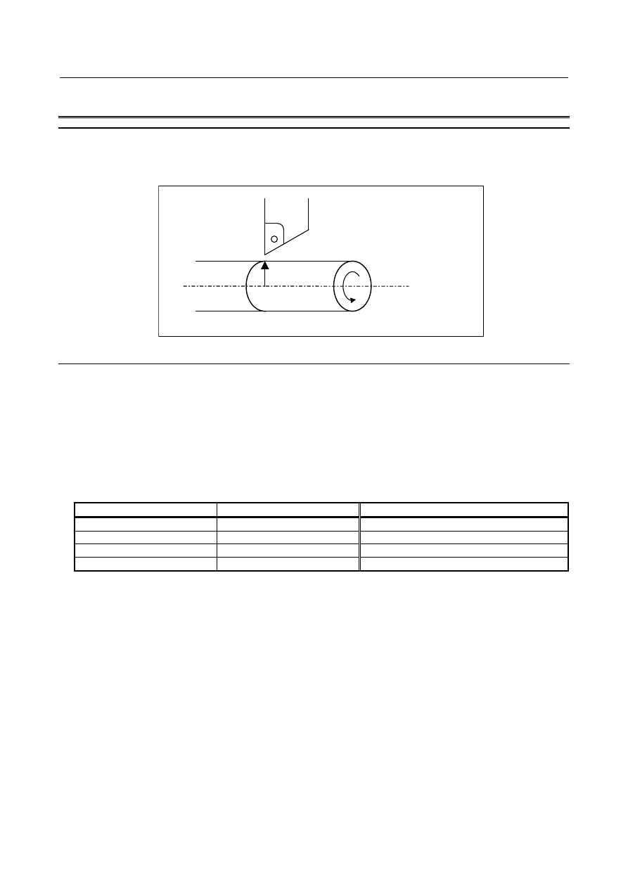
When a surface speed (in m/min or feet/min) is specified with an S code (a numeric value following S), 
the spindle speed is controlled so that the surface speed is kept constant with respect to the change in tool 
position. 

r

Surface speed S=2

p

r

N

Spindle speed N


Fig. 10.8 (a) Relationship between surface speed and spindle speed 


Explanation 

Specify constant surface speed control as follows: 
 

G96 S_ (Surface speed m/min (in metric input) or feet/min (in inch input)) 

To cancel constant surface speed control, specify the following: 
 

G97 S_ (Spindle speed min

-1

 
To perform constant surface speed control, the maximum spindle speed for each gear select signal issued 
from the PMC side must be set by parameters Nos. 3741-3744.   
The gear select signal is a 2 bit code signal (GR1, GR2). The relationship between the signal and gear 
number is : 

GR1 

GR2 

Gear number 

"0" 

"0" 

"1" 

"0" 

"0" 

"1" 

"1" 

"1" 

4* 

(* :Gear 4 is available only in the lathe specifications.) 
 

B-64693EN-1/01


10. SPINDLE SPEED FUNCTION


- 1515 - 

  - 

Example of Spindle Analog Output 

Assume that gear switching is two stage switching. If the spindle speed with the output 10 V is 1000 
min

-1

  for the low speed gear (G1) and 2000 min

-1

  for the high speed gear (G2), set these speeds to the 

parameters Nos. 3741 and 3742, respectively. In this case, the spindle output has the linear relationship 
shown below (Fig. 10.8 (b)): 


When gear 2 
selected 

When gear 1 
selected 

V

2


V

1


10 

600min

-1


1000min

-1


2000min

-1


G2 

G1 

Spindle output 
(Volt) 


Fig. 10.8 (b) 

 
Here, S = 60 m/min is given as the surface speed; if the position of the present X-axis cutter is 16 mm 
from the center, the spindle speed N becomes 600 min

-1

 (S = 2

p

r

N). Therefore, V

1

 (for G1) or V

2

  (for 

G2) is calculated inside the CNC and output to the machine side. 
 

V1 ; 6 (V) 


V2 ; 3 (V) 

The value of output voltage V is calculated automatically from the following equations: 
(i)  G96 
 

V=10S/2

p

rR 

R :  Spindle speed (min

-1

) at 10V output voltage (that is , spindle speed set by parameters Nos. 3741 

to 3744) 

S :  Surface speed (m/min) specified by S command 
r : 

Radius value in the X-axis direction (m) 

(ii)  G97 
 

V=10N/R 
R :  Spindle speed at 10V output voltage (min

-1

N :  Spindle speed given by S command (min

-1


  - 

Spindle Serial Output 

The output to the spindle in spindle serial output is a digital data. 
Therefore assume the following relation for calculation: 
Spindle analog output (voltage) 10V = Spindle serial output (digital data) 4095. 
The above calculation becomes as follows: 
The value of Spindle output D: 
(i)  G96 
 

D=4095S/2

p

rR 

R :  Spindle speed (min

-1

) at maximum spindle motor speed (that is , spindle speed set by 

parameters Nos. 3741 to No. 3744) 

S :  Surface speed (m/min) specified by S 
r : 

Radius value in the X-axis direction (m) 

(ii)  G97 
 

D=4095N/R 
R :  Spindle speed at maximum spindle motor speed (min

-1

N :  Spindle speed given by S command (min

-1


10. SPINDLE SPEED FUNCTION


B-64693EN-1/01


- 1516 - 

  - 

Constant surface speed control with no position coder 

With a machine having (or using) no position coder, constant surface speed control cannot usually be 
performed during feed per revolution, but is enabled by setting bit 1 (FPR) of parameter No. 3729 or bit 2 
(PCL) of parameter No. 1405 to 1. 
 

NOTE 

1  This function is not effective to spindle output control by the PMC. 
2  When the setting of bit 1 (FPR) of parameter No.3729 or bit 2 (PCL) of parameter 

No.1405 is 1, feed per revolution cannot be used to spindle output control by the 
PMC. 

 
For example, the following program is executed with G code system B and diameters specified. 

N1  G00 X50. Z10. ; 
N2  G96 G95 S12 ; 

Constant surface speed control and feed per revolution begin. 

N3  G01 X20. Z30. F10.; 
N4  Z50. ; 
N5  G97 S200;     


Constant surface speed control ends. 

N6  G00 Z200.; 
N7  M30 ; 


N3 

N4 


Fig. 10.8 (c) Feed per revolution without position coder 

 
In this program, block N2 issues a constant surface speed control command (G96), a surface speed 
command (S12 m/min), and a feed-per-revolution command (G95). Block N3 causes the CNC to change 
the spindle speed specification from 76.4 min

-1

  to 191 min

-1

  so as to maintain a constant surface speed 

during movement to X = 20. 
Meanwhile, the feed-per-revolution speed is changed according to the changed spindle speed 
specification, and used for movement along the feed axis. However, the specified spindle speed is 
clamped to the upper limit to the spindle speed specification (for the first spindle, using parameter No. 
3772). In the above program, the feed-per-revolution speed command F10 in block N3 corresponds to an 
actual speed of 764 (mm/min) to 1910 (mm/min). 
 

  - 

Command for maximum spindle speed clamping 

When rotation at the maximum spindle speed set by the parameter causes a problem in constant surface 
speed control, execute a command (M series: G92S_; T series: G50S_;) for maximum spindle speed 
clamping before starting constant surface speed control in order to prevent the spindle from rotating at a 
speed equal to or greater than a certain rotation speed.   
If bit 4 (CSA) of parameter No. 3712 is set to 1, it is possible to prevent the spindle from rotating at an 
unintended speed by issuing alarm PS5557, “NO MAX SP SPEED CLAMP COMMAND”, if constant 
surface speed control is specified when a command for maximum spindle speed clamping has not been 
executed after power-on due to a program error or an operation error such as execution of a machining 
program in an incorrect order.   
 

B-64693EN-1/01


10. SPINDLE SPEED FUNCTION


- 1517 - 

Spindle speed calculation during the 3-dimensional coordinate system 
conversion / the tilted working plane indexing 

In the constant surface speed control in the 3-dimensional coordinate system conversion / the tilted 
working plane indexing mode,  the coordinate system which is the standard of speed calculation can be 
changed by the parameter 3CS(No.11221#6). 
 

Table 10.8 (a)    The standard coordinate system of spindle speed calculation 

Parameter 3CS 

Coordinate system of standard 

Workpiece coordinate 

Program coordinate (3-dimensional coordinate system conversion)   

/ Feature coordinate (Tilted working plane indexing) 


Fig.10.8 (d)    Spindle speed calculation during the 3-dimensional coordinate system conversion / 

  the tilted working plane indexing 

 
Example) 
When the followings are set by the programming. 
-


the surface speed S=10(m/min) 

-


the axis as the calculation reference is X 


N1 G68 X0 Y0 Z0 I0 J1 K0 R-45.0   
N2 G01 G90 X0 Y0 Z0 F100.0 
N3 G96 S10 P1 
N4 X10.0 Y0 Z0 
N5 G97 
N6 G69 


Table 10.8 (b)    The spindle speed in N4 (calculation by relation of N=S/2

π

r) 

Parameter 3CS 

Radius value r (mm) In the axis (X) 

as the calculation reference 

Spindle speed N(mm

-1

7.0711 

225 

10.0 

159 


10. SPINDLE SPEED FUNCTION


B-64693EN-1/01


- 1518 - 

Multi-spindle control 

Clamp of maximum spindle speed 

When bit 0 (CLM) of parameter No.3785 is set to 0, and spindle selection by extended spindle name is 
enabled, if extended spindle name is commanded at clamp command of maximum spindle speed G92 
(G50 in G code system A of T series), alarm PS0539, “MAX SP SPEED CLAMP COMMAND ERROR” 
is issued. “S” has to be commanded at clamp command of maximum spindle speed. 
 
Example) 
Suppose that extended spindle name is set as follows. 
 

Table 10.8 (c)   

Spindle number 

Extended spindle name 

First spindle 

Second spindle 

SB 

 
If “G92 SB30 ;” is commanded, alarm PS0539, “MAX SP SPEED CLAMP COMMAND ERROR” is 
issued. Clamp of maximum spindle speed has to be commanded “G92 S30 ;”. If “S” is set as extended 
spindle name, alarm PS0539 is not issued. 
 

Selection of axis as the calculation reference in constant surface speed control 

When bit 0 (CLM) of parameter No.3785 is set to 0, and spindle selection by address P or extended 
spindle name of multi-spindle control is enabled, selection of axis as the calculation reference in constant 
surface speed control “G96 P_ ;” is commanded, alarm PS0190, “ILLEGAL AXIS SELECTED (G96)” is 
issued. Please change the setting of parameter No.3770 using programmable parameter input (G10) or the 
like in changing axis as the calculation reference in constant surface speed control. 
 
Example 
Suppose that spindle selection by address P is enabled. 

- If “G96 P_ ;” is commanded, alarm PS0190 is issued. 

  - If “G96 S_ P_ ;” is commanded, spindle selected by address P is controlled by constant surface speed 

control. 

 
Example 
Suppose that extended spindle name is set as Table 11.7 (c). 

- If “G96 P_ ;” is commanded, alarm PS0190 is issued. 

  - If “G96 S_ P_ ;” , or “G96 SB_ P_ ” is commanded, alarm PS0190 is issued. 
When extended spindle name is enabled, address P cannot be commanded at G96 block. 
 

G96 command without surface speed 

When bit 1 (G96) of parameter No.3785 is set to 1, and spindle selection by address P or extended spindle 
name is enabled, if G96 command without surface speed is commanded, alarm PS5355, “S CODE IS 
NOT COMMANDED AT G96” is issued. 


NOTE 


When spindle selection by address P or extended spindle name is enabled, if 
G96 is commanded without surface speed, surface speed which is commanded 
at previous G96 command is applied. Axis as the calculation reference in 
constant surface speed control which is commanded previously regardless of 
G96/G97 mode is applied. In order to prevent rotation of unexpected spindle by 
G96 command without surface speed, please command surface speed at G96 
command. 


B-64693EN-1/01


10. SPINDLE SPEED FUNCTION


- 1519 - 

System variable 

Clamp value of spindle maximum speed 

System variable 

number 

System variable name 

Attribute 

Description 

  #100959 

  [#_CSSSMAX] 

Spindle maximum speed commanded at clamp command 
of maximum spindle speed 

 
CNC reads block ahead of the executing block. The value of this system variable can be read after being 
executed clamp command of maximum spindle speed. 
 

Example 1) 

O1234 ; 
N10 G92 S5000 ; 
N20 G96 S60 ; 
N30 G01 X200.0 Z-300.0 F2.0 ; 
    : 
    : 
N60 G92 S2500 ; 
N70 #1 = #100959 ; 

 
Suppose that N30 block is executing. And suppose that CNC has read up to N70 block. Because N60 
block has not been executed, maximum spindle speed which can be read at N70 block is 5000[min

-1

commanded at N10 block. Therefore, 5000 is substituted for #1. In program of example 1, if 2500 has to 
be substituted for #1, command block preventing buffering (such as M code preventing buffering) before 
N70 block. 
 
In the following cases, #100959 is -1. 
-


Clamp command of maximum spindle speed G92 (G50 in G code system A of T series) has not been 
executed after turning on the power. 


Rigid tapping 

If rigid tapping is commanded during constant surface speed control, alarm PS0200, ”ILLEGAL S CODE 
COMMAND” is issued. Command rigid tapping after canceling constant surface speed control. 
 

Signal 

Gear selection signal (Input) GR2, GR1<Gn028.2,.1> 

Refer to Section, "SPINDLE SPEED CONTROL." 
 

Constant surface speed signal CSS<Fn002.2> 

  [Classification]  Output signal 
 

[Function]  This signal indicates that constant surface speed control is in progress.   


[Output cond.]  “1” indicates that constant surface speed control mode (G96) is in progress, while “0” 

indicates it is not. 


Signal address 


#7 

#6 

#5 

#4 

#3 

#2 

#1 

#0 

Fn002 


CSS 


10. SPINDLE SPEED FUNCTION


B-64693EN-1/01


- 1520 - 

Parameter 


#7 

#6 

#5 

#4 

#3 

#2 

#1 

#0 

1405 


PCL 


[Input type]  Parameter input 


[Data type]  Bit path 


#2  PCL

  The function for constant surface speed control without the position coder is: 

0: 

Not used. 

1: 

Used. 


NOTE 

1  Enable constant surface speed control (bit 0 (SSC) of parameter 

No.8133 is 0). 

2  This function is not effective to spindle output control by the PMC. 
3  When this parameter is set to 1, feed per revolution cannot be used 

to spindle output control by the PMC. 


3741 


Maximum spindle speed for gear 1 


3742 


Maximum spindle speed for gear 2 


3743 


Maximum spindle speed for gear 3 


3744 


Maximum spindle speed for gear 4 


[Input type]  Parameter input 


[Data type]  2-word spindle 


[Unit of data]  min

-1


[Valid data range]  0 to 99999999 

Set the maximum spindle speed corresponding to each gear. 


Spindle motor max. clamp speed   
(Parameter No.3736) 

Spindle speed command   
(S command) 

Max. speed (4095, 10V) 

Spindle motor minimum clamp speed   
(Parameter No.3735) 

Spindle motor speed 

Gear 1   
Max. speed 
(Parameter 
No.3741) 

Gear 2   
Max. speed 
(Parameter 
No.3742) 

Gear 3   
Max. speed 
(Parameter 
No.3743) 


B-64693EN-1/01


10. SPINDLE SPEED FUNCTION


- 1521 - 


#7 

#6 

#5 

#4 

#3 

#2 

#1 

#0 

3705 


EVS 


ESF 


NSF 


ESF 


[Input type]  Parameter input 


[Data type]  Bit path 


#0  ESF

 When the spindle control function (Spindle analog output or Spindle serial output) is used, 

and the constant surface speed control function is used or bit 4 (GTT) of parameter No. 
3706 is set to 1:     
0: 

S codes and SF are output for all S commands.   

1: 

For the T series: 
 

S codes and SF are not output for an S command in the constant surface speed 
control (G96) mode and a command for maximum spindle speed clamping 
(G92 S_; (G50 for G code system A)). 


For the M series: 
 

S codes and SF are not output for an S command in the constant surface speed 
control (G96) mode. 


NOTE 


The operation of this parameter varies between the T series and M 
series. 
For the T series:   

This parameter is valid when bit 4 (EVS) of parameter No. 3705 
is set to 1. 

For the M series:   

For an S command for maximum spindle speed clamping   
(G92 S_;), SF is not output, regardless of the setting of this 
parameter. 


#4  EVS

 When the spindle control function (Spindle analog output or Spindle serial output) is used, 

S codes and SF are: 
0: 

Not output for an S command.   

1: 

Output for an S command.   

The output of S codes and SF for an S command in constant surface speed control mode 
(G96), or for an S command used to specify maximum spindle speed clamping (G92 S_; 
(G50 for G code system A)) depends on the setting of bit 0 (ESF) of parameter No. 3705. 


#5  NSF

  For the M series, when a T type gear is selected (with bit 4 (GTT) of parameter No. 3706 

set to 1 or enable constant surface speed control (bit 0 (SSC) of parameter No.8133 is 0)), 
and an S code is specified: 
0: 

SF is output. 

1: 

SF is not output. 


NOTE 


This parameter does not affect S code output. For an S command 
for maximum spindle speed clamping (G92 S_;), SF is not output, 
regardless of the setting of this parameter. 


Content      ..     193      194      195      196     ..