FANUC Series 0i-MODEL F Plus. CONNECTION MANUAL (FUNCTION) - page 191
 

  Index      Manuals     FANUC Series 0i-MODEL F Plus. CONNECTION MANUAL (FUNCTION) B-64693EN-1/01


Search            copyright infringement  


Content      ..     189      190      191      192     ..


FANUC Series 0i-MODEL F Plus. CONNECTION MANUAL (FUNCTION) - page 191


10. SPINDLE SPEED FUNCTION


B-64693EN-1/01


- 1482 - 

The speed commands output to the spindle motor are as follows: 


For the serial spindle, the speed commands are processed as values 0 to 16383 between the CNC and 
spindle control unit. 


For the analog spindle, the speed commands are output to the analog voltage signal SVC as analog 
voltages 0 to 10 V. 

 
The following descriptions exemplify the analog spindle. However, they can be applied to the serial 
spindle on the assumption that spindle motor speed with analog voltage 10 V corresponds to the 
maximum spindle motor speed. 
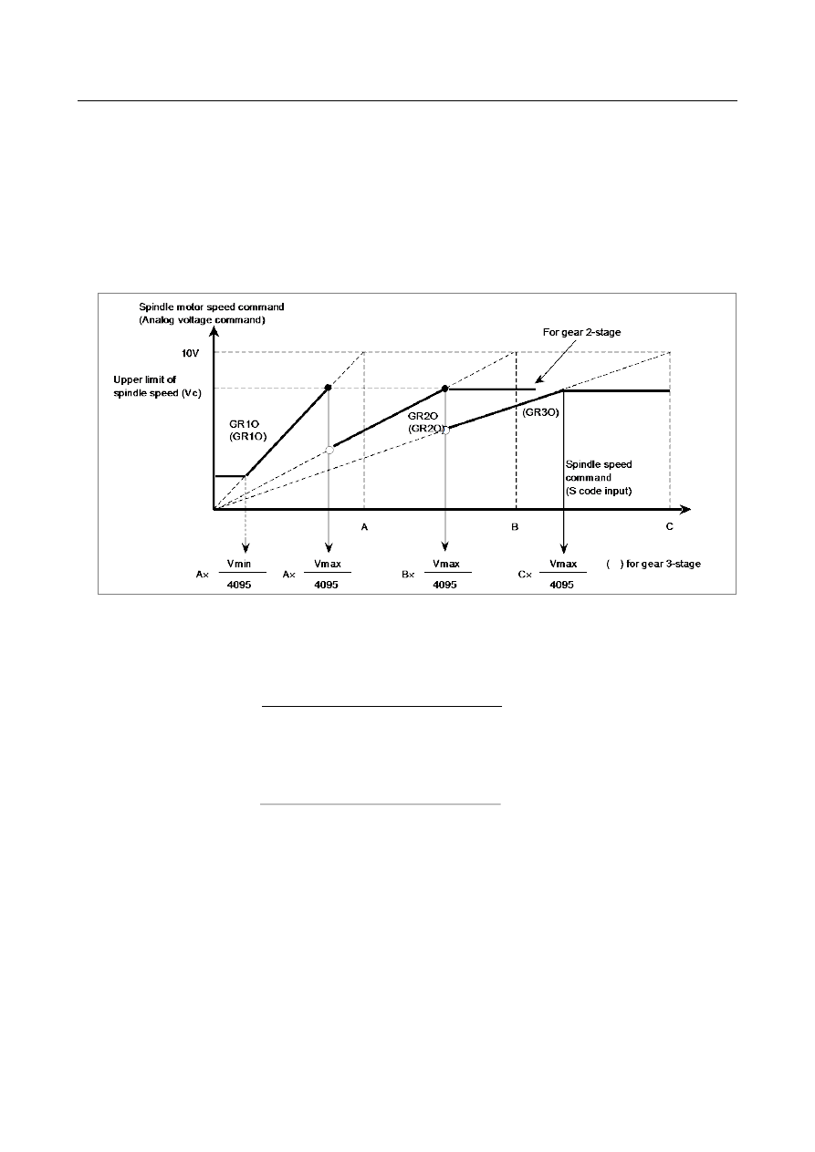
(i)  M type gear change method A (See Fig. 10.5 (b).) 


Fig. 10.5 (b) S code input and output voltage 


Set the following values as parameters: 


Constant Vmax: for upper limit of spindle speed (parameter No. 3736) 


Upper limit of spindle speed 


Vmax = 4095 

×


Spindle speed at command voltage 10V 


Constant Vmin; for lower limit of spindle speed (parameter No. 3735) 


Lower limit of spindle speed 


Vmin = 4095 

×


Spindle speed at command voltage 10V 


Spindle speed A (min

-1

) ; at command voltage 10V and low gear (parameter no. 3741) 


Spindle speed B (min

-1

) ; at command voltage 10V and high gear (or middle-high gear) 

(parameter no. 3742) 


Spindle speed C (min

-1

) ; at command voltage 10V and high gear (parameter no. 3743)(Gear 

3-stage) 


B-64693EN-1/01


10. SPINDLE SPEED FUNCTION


- 1483 - 

NOTE 


If a specified voltage of 10 V is already higher than the acceptable input voltage 
for the spindle drive system, calculate hypothetically the spindle speed that 
corresponds to 10 V using a proportional calculation method and use it instead. 
Now, in response to the specified S code, the speed command and gear select 
commands (GR3O, GR2O, GR1O) are output to the spindle motor as shown in 
Fig. 10.5 (b). 

 
(ii)  Gear change point during tapping cycle mode (G84, G74) 
 

In case of G84 (tapping cycle) or G74 (counter tapping cycle) the gear shift speed is changed by bit 
3 (SGT) of parameter No. 3705. In this case, gear shift is performed at the speed set by parameters 
Nos. 3761 and 3762 (Fig. 10.5 (c)). 


Fig. 10.5 (c) S code input and output voltage (in tapping) 


10. SPINDLE SPEED FUNCTION


B-64693EN-1/01


- 1484 - 

M


(iii)  M type gear change method B (M series) (See Fig. 10.5 (d).) 
 

The speed (min

-1

) at which the low-speed and the high-speed gears are changed can be set as 

parameters Nos. 3751 and 3752 by setting bit 2 (SGB) of parameter No. 3705. When a 3-stage gear 
is used, it is possible to set the speeds (min

-1

) for switching low-speed and medium-speed gears, and 

medium-speed and high-speed gears, using parameters Nos. 3751 and 3752. 


Fig. 10.5 (d) M type gear change B 

 
When using this function, set the following parameters: 


Constant Vmax (Parameter No. 3736) related to the upper limit of spindle motor speed (min

-1


Upper limit of spindle motor speed 


Vmax = 4095 

×


Spindle motor speed when the command voltage is 10V 


Constant Vmin (Parameter No. 3735) related to the lower limit of spindle motor speed (min

-1


Lower limit of spindle motor speed   


Vmin = 4095 

×


Spindle motor speed when the command voltage is 10V 


Constant Vmaxl (Parameter No. 3751) related to the upper limit of spindle motor speed (min

-1

) with 

low-speed gears 


Upper limit of spindle motor speed with low-speed gears 


Vmaxl = 4095 

×


Spindle motor speed when the command voltage is 10V 


B-64693EN-1/01


10. SPINDLE SPEED FUNCTION


- 1485 - 


Constant Vmaxh (Parameter No. 3752) related to the upper limit of spindle motor speed (min

-1

) with 

high-speed gears (medium-speed gear for 3-stage gear) 


Upper limit of spindle motor speed with high-speed gears   


Vmaxh = 4095 

×


Spindle motor speed when the command voltage is 10V 


Spindle speed A (Parameter No. 3741) (min

-1

) with low-speed gears when the command voltage is 

10V 


Spindle speed B (Parameter No. 3742) (min

-1

) with high-speed gears when the command voltage is 

10V (medium-speed gear for 3-stage) 


Spindle speed C (Parameter No. 3743) (min

-1

) with high-speed gears when the command voltage is 

10V (3-stage gear) 

Spindle motor speed commands and gear selecting signals (GR1O, GR2O, GR3O) are issued on each S 
code command as shown in the Fig. 10.5 (d): 
 

  CAUTION 

1  In a tapping cycle when bit 3 (SGT) of parameter No. 3705 is set, the gears are 

changed over at the gear changing point for tapping. 

2  For this function (bit 2 (SGB) of parameter No. 3705 = 1), when only one-stage 

gear is used, the voltage corresponding to the upper limit value to the spindle 
motor is calculated using Vmaxl, and when 2-stage gear is used, it is calculated 
according to Vmaxh. Therefore, when SGB is 1, set Vmaxl when only one-stage 
gear is used, Vmaxl and Vmaxh when 2-stage gear is used. 

 
Bit 6 (GMB) of parameter No. 3712 can be used to select the maximum spindle motor speed for each 
gear.   
 
When the bit 6 (GMB) of parameter No. 3712 is set to 0: 
 

The maximum motor speed when each gear is used is clamped by parameters No. 3741 to 3743 or 
parameter No. 3736.   


S1 

S1 

Maximum spindle 
speed 

Maximum speed of the 
spindle motor 
No.3736 

Gear switching point 

Spindle speed clamp point of each gear   


Spindle motor speed when 
switching from gear 2 to 
gear 3 
No.3752 

Spindle motor speed when 
switching from gear 1 to 
gear 2 
No.3751 

Maximum spindle 
speed for gear 1 
No.3741 

Maximum spindle 
speed for gear 2 
No.3742 

Maximum spindle 
speed for gear 1 

Maximum spindle 
speed for gear 2 


Fig. 10.5 (e) When the bit 6 (GMB) of parameter No. 3712 is set to 0 


10. SPINDLE SPEED FUNCTION


B-64693EN-1/01


- 1486 - 

When the bit 6 (GMB) of parameter No. 3712 is set to 1: 
 

The maximum motor speed of gear 1 is clamped at the motor speed of the switching point from gear 
1 to gear 2 and the maximum motor speed of gear 2 is clamped at the motor speed of the switching 
point from gear 2 to gear 3.   


S1 

S1 

Maximum spindle 
speed for gear 1 


Maximum spindle 
speed 


Maximum speed of the 
spindle motor 
No.3736 


Spindle motor speed when 
switching from gear 2 to 
gear 3 
No.3752 


Maximum spindle 
speed for gear 2 


Maximum spindle 
speed for gear 1 
No.3741 


Maximum spindle 
speed for gear 2 
No.3742 


Gear switching point 
Spindle speed clamp point of each gear 


Spindle motor speed when 
switching from gear 1 to 
gear 2 
No.3751 


Fig. 10.5 (f) When the bit 6 (GMB) of parameter No. 3712 is set to 1 


  - 

Time chart 

When S code is commanded, the I/O signal time chart is : 
(i)  When Gear select signal does not change 


In this case, the SF signal is not output and the CNC advances to the next block automatically after 
the next spindle speed command is output. 


B-64693EN-1/01


10. SPINDLE SPEED FUNCTION


- 1487 - 

(ii)  When Gear select signal change 


In this case, the gear select signal is output; after elapse of the time constant set by parameter (TMF), 
the SF signal  is output. After another TMF elapse, the spindle speed command is output. On the 
PMC side, change the gears by this SF signal, and return the FIN signal after the end of gear change. 
The time chart for SF and FIN signals is the same as in S code output. TMF, set by parameter No. 
3010, is common to M, S and T functions. 


Moreover, specifying bit 6 (SFA) of parameter No. 3705 can specify that the SF signal be output 
even if no gear change is used. 


  - 

Details of T type (Input of GR1, GR2) 

To perform the T type gear change, the maximum spindle speed for each gear side must be set in 
parameters Nos. 3741 to 3744.   
The gear select signal is a 2 bit code signal (GR1, GR2). The relationship between the signal and gear 
number is Table 10.5 (b): 

Table 10.5 (b) 

Gear select signal 

Gear No. 

Parameter No. for max. spindle speed 

GR1 

GR2 

"0" 

"0" 

No. 3741 

"1" 

"0" 

No. 3742 

"0" 

"1" 

No. 3743 

"1" 

"1" 

No. 3744 

 
The following descriptions apply to the analog spindle. Like the descriptions of the M type, they also 
apply to the serial spindle on the assumption that spindle motor speed with analog voltage 10 V 
corresponds to the maximum spindle motor speed. 
In addition, for the speed command output to the spindle motor, analog voltages 0 to 10 V for analog 
spindle control correspond to digital data 0 to 16383 for serial spindle control. However, it might be 
easier if you consider them code signals from 0 to 4095 for convenience sake without distinguishing 
between serial and analog spindles. 
Assume that gear switching is two stage switching. If the spindle speed with the output voltage 10 V is 
1000 min

-1

 for the low speed gear (G1) and 2000 min

-1

 for the high speed gear (G2), set these speeds by 

the parameters Nos. 3741 and 3742. In this case, the analog voltage has the linear relationship shown 
below (Fig. 10.5 (g)).   

10. SPINDLE SPEED FUNCTION


B-64693EN-1/01


- 1488 - 


Fig. 10.5 (g) 

 
When spindle speed S=600 is given, V1 (for G1) or V2 (for G2) in the Fig. 10.5 (g) is calculated inside 
the CNC and output to the machine side. 
V1 ; 6 (V) 
V2 ; 3 (V) 
The value of output voltage V is calculated automatically from the following equations: 
V = 10N / R 
R : Spindle speed at 10V output voltage 
N : Spindle speed given by S command of 5 digits 
This is equivalent to the G97 mode for constant surface speed control. 
See "CONSTATNT SURFACE SPEED CONTROL" for operations during the constant surface speed 
control mode (G96). 
 

  - 

Determining spindle speed command output R01O-R12O (Output) 

Using the above processing for gear change, the CNC calculates the speed command output to the spindle 
motor that is necessary to obtain the specified spindle speed with the gear. 
The calculation result is output to the PMC through S12-bit code signals indicating a value 0 to 4095. 
(R12O to R01O<Fn037.3 to Fn036.0>) 
Then, according to the selection by the signal used to select the spindle motor speed command  SIND 
<Gn033.7>, the speed command output to the spindle motor is determined. 
 

SIND signal <Gn033.7> 

Speed command output to spindle motor 

"0" 

Speed command output calculated by CNC 

"1" 

Speed command output set by PMC 
Also see "SPINDLE OUTPUT CONTROL BY THE PMC". 


  - 

Polarity of spindle speed command output 

The speed command output to the spindle motor is determined as described above, but the actual output 
polarity is determined by the CNC as follows (Table 10.5 (c)): 
 

Table 10.5 (c) 

Bit 7 (TCW) of parameter No. 3706  Bit 6 (CWM) of parameter No. 3706 

Output polarity 

+(M03/M04 command) 

-(M03/M04 command) 

+(M03 command), -(M04 command) 

-(M03 command), +(M04 command) 

 
Then, according to the selection by the signal used to select the polarity of the spindle motor speed 
command SSIN <Gn033.6>, the output polarity of the speed command output  to the spindle motor is 
determined. 

B-64693EN-1/01


10. SPINDLE SPEED FUNCTION


- 1489 - 

SSIN signal <Gn033.6> 

Output polarity of speed command output to spindle motor 

"0" 

Output polarity determined by CNC 

"1" 

Output polarity set by PMC 
Also see "SPINDLE OUTPUT CONTROL BY THE PMC". 


NOTE 


When bit 7 (TCW) of parameter No. 3706 is 1, and the output polarity is to be 
determined by the CNC, the CNC cannot determine the output polarity if M03 or 
M04 has not been specified even once since power-on. As a result, no command 
is output to the spindle. 


  - 

Command output to the spindle control unit 

According to the speed command output and the polarity determined so far, the command is sent to the 
spindle control unit as follows: 


For serial spindle 

 Digital data 0 to 

±

16383 


For analog spindle 

 Analog voltage 0 to 

±

10 V 


  - 

Conditions for stopping spindle speed command output 

A command being output to the spindle is set to 0 when *SSTP is set to “0” and when a command that 
sets the spindle speed command output to 0 such as a S0 command is specified. 
With M05, emergency stop, and a reset, the CNC does not set the command output to the spindle to 0. 
 

  - 

Position coder feedback signal 

The position coder is necessary for thread cutting or feed per revolution. 
The position coder detects the actual spindle speed and the one-rotation signal (used to detect a fixed 
point on the spindle for threading). Number of pulses output from the position coder is set in parameter 
No. 3720. 
When the gear ratio between the position coder and spindle is to be used, set the gear ratio for the position 
coder and spindle in parameters Nos. 3721 and 3722, respectively. 
However, in the machine to do thread cutting, connect mechanically between the spindle and position 
coder by the gear ratio=1:1. And these parameters set the No.3721=0, No.3722=0. (It is the setting for the 
gear ratio 1:1.) 
In the general thread cutting, the same thread grooves must be cut several times. To cutting the same 
thread groove repeatedly, it is necessary to detect the fixed point on the spindle. (One fixed point in the 
one rotation of the spindle.) One-rotation signal is used for the detection of the one fixed point. Typically, 
the one-rotation signal is generated on the one fixed point in the one rotation of the position coder. 
For these reasons, when doing the thread cutting, the position coder and spindle must be connected by the 
gear ratio 1:1. 
See "RIGID TAPPING" for position coder connection for rigid tapping. 
 

  - 

Speed arrival signal SAR <Gn029.4> 

The spindle speed arrival signal SAR is an input signal used as a condition for the CNC to start cutting 
feed. This signal is used generally when cutting feed should be started after the spindle reaches the 
specified speed. 
In this case, a sensor is used to check the spindle speed. The detected speed is sent to the CNC via the 
PMC. 
When the above operation is performed continuously using the PMC ladder, however, cutting feed may 
be started based on the SAR signal indicating the previous spindle state (spindle speed before change), if 
the spindle speed change command and the cutting feed command are issued at the same time. 
To avoid the above problem, monitoring the SAR signal can be deferred for a time specified by parameter 
No. 3740 after the S command or cutting feed command was issued. 
When using the SAR signal, set bit 0 (SAR) of parameter No. 3708 to 1. 


Content      ..     189      190      191      192     ..