FANUC Series 0i-MODEL F Plus. CONNECTION MANUAL (FUNCTION) - page 187
 

  Index      Manuals     FANUC Series 0i-MODEL F Plus. CONNECTION MANUAL (FUNCTION) B-64693EN-1/01


Search            copyright infringement  


Content      ..     185      186      187      188     ..


FANUC Series 0i-MODEL F Plus. CONNECTION MANUAL (FUNCTION) - page 187


9. AUXILIARY FUNCTION


B-64693EN-1/01 

- 1450 - 

Operation


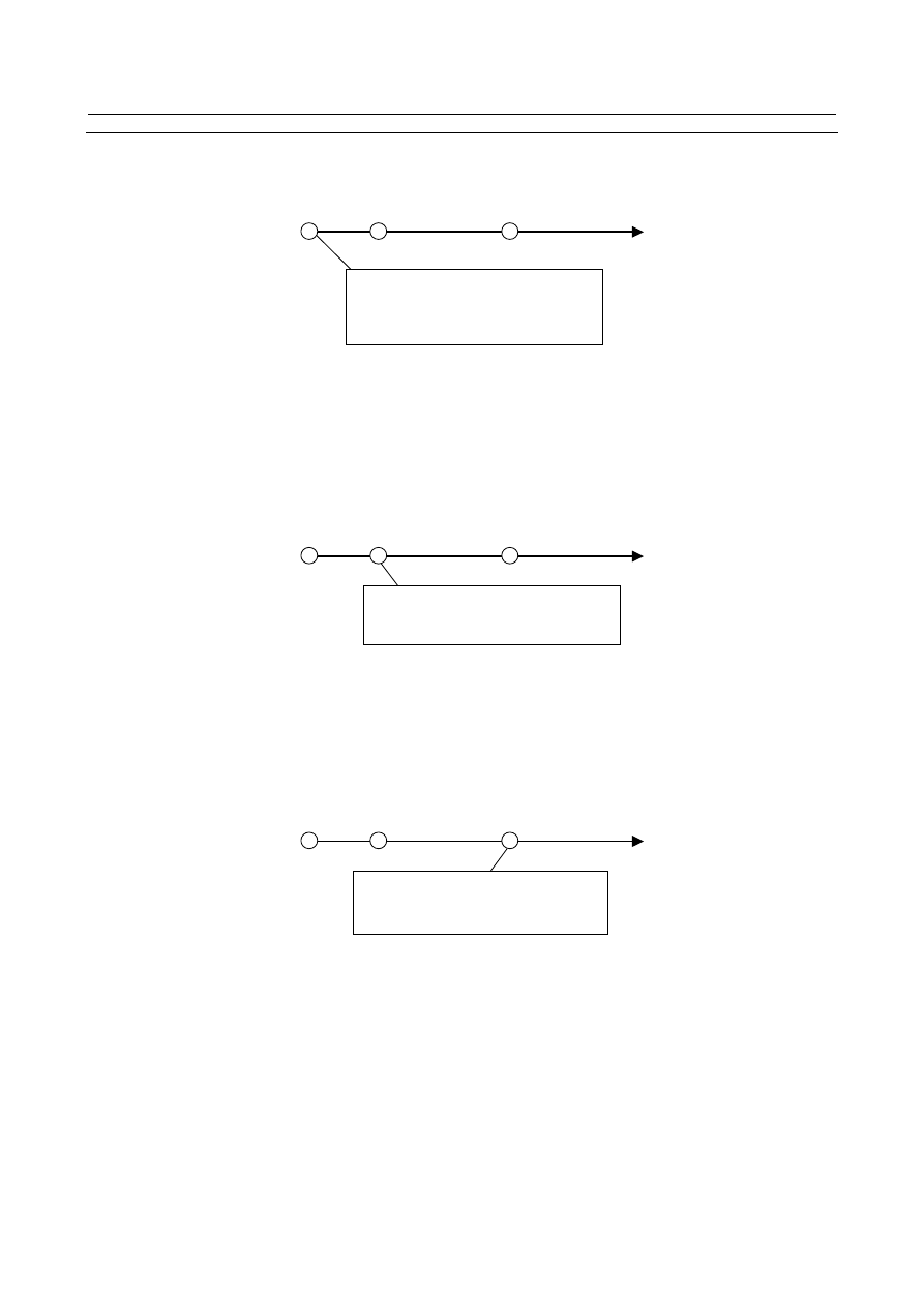
(1)  At the start point of movement block, M/S/T/B codes (m01,m02,m03,b01,s01,t01) of movement 

block are output to PMC, and moving is started.   


Mm01,Mm02,Mm03,Bb01,Ss01,Tt01 of   

movement block are output to PMC at the   

start point. 

The 1st output start point 

The 2nd output start point 


(2)  When moving to the 1st output start point that is specified at the 1st G50.9 block, if FIN processing 

of   
M/S/T/B code which was output to PMC in (1) has completed, M code (m11,m12,m13) and B code 
(b11) of the 1st G50.9 block are output to PMC. 
If FIN processing has not completed, M code (m11,m12,m13) and B code (b11) are  not  output to 
PMC  at the 1st output start  point. They are output immediately after  FIN processing completes. 
Code signals and strobe signals are output to the same signal address as usual auxiliary function. 


Mm11,Mm12,Mm13,Bb11 specified at the   

1st G50.9 block are output to PMC 

The 1st output start point 

The 2nd output start point 


(3)  When moving to the 2nd  output  start  point  that is specified  at the 2nd  G50.9  block, if FIN 

processing of  M/S/T/B code  which was output to  PMC in (2) has completed, M code 
(m21,m22,m23) and B code (b21) of the 2nd G50.9 block are output to PMC. 
If FIN processing has not completed, M code (m21,m22,m23) and B code (b21) are  not  output to 
PMC at the 2nd output start point. They are output immediately after FIN processing completes.   


The 1st output start point 

The 2nd output start point 


Mm21,Mm22,Mm23,Bb21 specified at the 

2nd G50.9 block are output to PMC. 


(4)  When movement completes, if absolute coordinate has not reached  the value that was  specified  at 

G50.9 blocks, the alarm PS5331, “ILLEGAL COMMANDED POSITION“ occurs. 


B-64693EN-1/01


9. AUXILIARY FUNCTION


- 1451 - 

Specification of output start point 


When coordinates for 2 axes are specified 


Specified coordinate 

at G50.9 block.


Absolute coordinate when 

G50.9 executes.


Auxiliary functions are output when absolute 

coordinate enters this area.


When coordinate for 1 axis is specified 


Specified coordinate 

at G50.9 block. 


Absolute coordinate when 

G50.9 executes.


Auxiliary functions are output when absolute 

coordinate enters this area.


Priority of auxiliary function output 

If absolute coordinate have entered the area that was specified at the 2nd G50.9 block while they have not 
entered the area that was specified at the 1st G50.9 block, auxiliary function of the 2nd G50.9 block are 
not output  at that time. After absolute coordinate  entered the area that was specified at the 1st G50.9 
block and FIN processing completed, auxiliary function of the 2nd G50.9 block are output finally.


Alarm at movement completion 

When movement completes, if absolute coordinate has not reached the value that was specified at G50.9   
blocks, the alarm PS5331, ”ILLEGAL COMMANDED POSITION” occurs. 
 
The alarm PS5331, ”ILLEGAL COMMANDED POSITION” occurs if next block after G50.9 block is no 
movement command because absolute coordinate does not reach to the value that was specified at G50.9 
block. 
Example 1) M code   

G00 X100. ; 
G50.9 X200. M128 ; 
M01; 

 The alarm PS5331 occurs. 

G00 X300. ; 
 

Example 2) Empty block 

G00 X100. ; 
G50.9 X200. M128 ; 
; (Empty block)   

 The alarm PS5331 occurs. 

G00 X300. ; 
 

9. AUXILIARY FUNCTION


B-64693EN-1/01 

- 1452 - 

Parameter 


#7 

#6 

#5 

#4 

#3 

#2 

#1 

#0 

3001 


MHI 


[Input type]  Parameter input 


[Data type]  Bit path 


#7


MHI

  Handshake of strobe and completion signals for the M, S, T, and B 

0: 

Normal 

1: 

High-speed 


#7 

#6 

#5 

#4 

#3 

#2 

#1 

#0 

3104 


DAC 

DAL 


[Input type]  Parameter input 


[Data type]  Bit path 


#6  DAL

  The displayed absolute position is 

0: 

The actual position that takes tool length offset into account. 

1: 

The programmed position that does not take tool length offset into account. 


NOTE 


In lathe systems, whether a tool offset is excluded from displaying 
absolute position is determined by the setting of bit 1 (DAP) of 
parameter No.3129. 


#7


DAC

  When an absolute position are displayed: 

0: 

Values not excluding the amount of travel based on cutter compensation and tool 
nose radius compensation are displayed. 

1: 

Values excluding the amount of travel based on cutter compensation and tool nose 
radius compensation (programmed positions) are displayed. 


NOTE 


When the parameter DAC is set to 1, in the command like circle 
interpolation where the cutter compensation vector is changed 
constantly, an absolute position is not correctly displayed during its 
interpolation except its start point and its end point. 


#7 

#6 

#5 

#4 

#3 

#2 

#1 

#0 

3129 


DAP 


[Input type]  Parameter input 


[Data type]  Bit path 


#1  DAP

  For absolute coordinate display: 

0: 

The actual position including a tool offset (tool movement) is displayed. 

1: 

The programmed position excluding a tool offset (tool movement) is displayed. 


B-64693EN-1/01


9. AUXILIARY FUNCTION


- 1453 - 

NOTE 


In machining center systems, whether the tool length offset is 
excluded from displaying absolute position is determined according 
to the setting of bit 6 (DAL) of parameter No.3104. 


Signal 

Auxiliary function code signals M00 to M31<Fn010 to Fn013> 

2nd M function code signals M200 to M215<Fn014 to Fn015> 

3rd M function code signals M300 to M315<Fn016 to Fn017> 
Auxiliary function strobe signal MF<Fn007.0> 
2nd M Function strobe signal MF2<Fn008.4> 
3rd M Function strobe signal<Fn008.5> 

    [Classification]  Output signal 
 

  [Function]  These signals report that M codes have been specified. 


[Output cond.]  About output condition, procedure etc, please refer to “FANUC Series 0

i

-MODEL F Plus 

CONNECTION MANUAL (FUNCTION)  10.1 AUXILIARY FUNCTION/2ND 
AUXILIARY FUNCTION”. 
 

2nd auxiliary function code signals B00 to B31<Fn030 to Fn033> 
2nd auxiliary function strobe signal BF<Fn007.7> 

  [Classification]  Output signal 
 

[Function]  These signals report that second auxiliary functions have been specified. 


[Output cond.]  About output condition, procedure etc, please refer to “FANUC Series 0

i

-MODEL F Plus 

CONNECTION MANUAL (FUNCTION)  10.1 AUXILIARY FUNCTION/2ND 
AUXILIARY FUNCTION”. 
 

End signal FIN<Gn004.3> 


[Classification]


Input signal 


[Function]  This signal reports the completion of an  auxiliary function, a  spindle function, a  tool 

function, a 2nd auxiliary function, or an external operation function. 


[Operation]  About input condition, procedure etc, please refer to “FANUC Series 0

i

-MODEL F Plus 

CONNECTION MANUAL (FUNCTION)  10.1 AUXILIARY FUNCTION/2ND 
AUXILIARY FUNCTION”. 
 

Auxiliary function completion signal MFIN<Gn005.0> 


[Classification]


Input signal 


[Function]  Reports that the execution of an  auxiliary function using the high-speed M/S/T/B 

interface is completed. 


[Operation]  About input condition, procedure etc, please refer to “FANUC Series 0

i

-MODEL F Plus 

CONNECTION MANUAL (FUNCTION)  10.1 AUXILIARY FUNCTION/2ND 
AUXILIARY FUNCTION”. 
 

2nd M function completion signal MFIN2<Gn004.4> 
3rd M function completion signal MFIN3<Gn004.5> 


[Classification]


Input signal 


[Function]  Indicate that when the high-speed  M/S/T/B  interface is used for multiple M commands 

per block, the 2nd to 3rd M functions have been completed. 


[Operation]  About input condition, procedure etc, please refer to “FANUC Series 0

i

-MODEL F Plus 

CONNECTION MANUAL (FUNCTION)  10.1 AUXILIARY FUNCTION/2ND 
AUXILIARY FUNCTION”. 
 

9. AUXILIARY FUNCTION


B-64693EN-1/01 

- 1454 - 

2nd auxiliary function completion signal BFIN<Gn005.7> 


[Classification]


Input signal 


[Function]  Reports that the execution of a second auxiliary function using the high-speed M/S/T/B 

interface is completed 


[Operation]  About input condition, procedure etc, please refer to “FANUC Series 0

i

-MODEL F Plus 

CONNECTION MANUAL (FUNCTION)  10.1  AUXILIARY FUNCTION/2ND 
AUXILIARY FUNCTION”. 
 

Auxiliary function during axis movement output signal   

MVAF1<Fn316.4>, MVAF2<Fn316.5> 


[Classification]  Output signal 


[Function]  Indicates that auxiliary functions specified at G50.9 blocks are outputting. 

1st output point 

: MVAF1 

2nd output point  : MVAF2 


[Output cond.]  These signals turn to “1” when 

The  absolute coordinate reach the 1st output point and auxiliary function code 
signals M00 to M31<Fn010 to Fn013> or 2nd auxiliary function code signals B00 to 
B31<Fn030 to Fn033> are output. 

The  absolute coordinate reach the 2nd output point and auxiliary function code 
signals M00 to M31<Fn010 to Fn013> or 2nd auxiliary function code signals B00 to 
B31<Fn030 to Fn033> are output. 

These signals turn to “0” when 

Each FIN processing has been completed. 

Reset occurs 


Signal address 


#7 

#6 

#5 

#4 

#3 

#2 

#1 

#0 

Gn004 


MFIN3 

MFIN2 

FIN 


Gn005 


BFIN 

AFL 


TFIN 

SFIN 


MFIN 


#7 

#6 

#5 

#4 

#3 

#2 

#1 

#0 

Fn007 


BF 


TF 

SF 


MF 


Fn008 


MF3 

MF2 


Fn010 


M07 

M06 

M05 

M04 

M03 

M02 

M01 

M00 


Fn011 


M15 

M14 

M13 

M12 

M11 

M10 

M09 

M08 


Fn012 


M23 

M22 

M21 

M20 

M19 

M18 

M17 

M16 


Fn013 


M31 

M30 

M29 

M28 

M27 

M26 

M25 

M24 


Fn014 


M207 

M206 

M205 

M204 

M203 

M202 

M201 

M200 


Fn015 


M215 

M214 

M213 

M212 

M211 

M210 

M209 

M208 


Fn016 


M307 

M306 

M305 

M304 

M303 

M302 

M301 

M300 


Fn017 


M315 

M314 

M313 

M312 

M311 

M310 

M309 

M308 


Fn030 


B07 

B06 

B05 

B04 

B03 

B02 

B01 

B00 


Fn031 


B15 

B14 

B13 

B12 

B11 

B10 

B09 

B08 


Fn032 


B23 

B22 

B21 

B20 

B19 

B18 

B17 

B16 


Fn033 


B31 

B30 

B29 

B28 

B27 

B26 

B25 

B24 


Fn316 


MVAF2 

MVAF1 


B-64693EN-1/01


9. AUXILIARY FUNCTION


- 1455 - 

Example of ladder sequence 


Axes movement 

       Axes movement 

M code signals 
<Fn010-Fn013> 


The 1st output start point 

MF<Fn007.0> 
 

FIN<Gn004.3> 

Mm01 

Mm11 

The 2nd output start point 

Mm21 

MVAF1<Fn316.4> 

MVAF2<Fn316.5> 


Alarm and message 

Number 

Message 

Description 

PS5330 

G50.9 FORMAT ERROR 

There is not coordinates value specification in G50.9 
block. 

There is not M code, B code command in the G50.9 
block. 

G50.9 is commanded in canned cycle mode. 

3 blocks of G50.9 block are commanded consecutively. 

PS5331 

ILLEGAL COMMANDED POSITION 

It didn't reach a commanded absolute coordinate value. The 
movement command or absolute coordinates at G50.9 
block are wrong. 


Note 

Tool nose radius compensation/Cutter compensation C 

Because G50.9 block is treated as a block  without  movement,  “Tool nose radius compensation” and 
“Cutter  compensation C” are temporarily canceled when two G50.9 blocks are commanded 
consecutively. 
 

Tool compensation 

When tool compensation amount is changed by T code after the G50.9 block, absolute coordinate value 
changes according to tool compensation amount. Therefore, absolute coordinate value sometimes enters   
the area specified by G50.9 block, at the head of the movement block. 
 

Program restart 

The histories of M code displayed in the screen of program restart are not in actual output order but in   
commanded block order. 
 

Multiple M commands in a single block 

The parameter M3B (No.3404#7) must be set to 1 in order to command multiple M codes in one block. 
 

9. AUXILIARY FUNCTION


B-64693EN-1/01 

- 1456 - 

M30, M02, M00, M01 

Decode signals DM30, DM02, DM01, DM00 are not output while axes are moving if M30, M02, M01, 
M00 are specified at G50.9 block. These decode signals are output at movement completion, but not 
output if FIN processing for M30, M02, M01, M00 have already completed. 
 

M98, M198 

Subprogram call M code (M98, M198) cannot be commanded at G50.9 block. 
The alarm PS0076, ”PROGRAM NOT FOUND” occurs. 
 

Macro call M code 

Custom macro call M code cannot be commanded at G50.9 block. 
 

Tool life management, Tool management 

Even if the M code (M06, etc.) which counts tool life is commanded at G50.9 block, tool life count isn't 
done. 
 

Waiting M code 

Even if a waiting M code is commanded at the G50.9 block, waiting function isn't executed. It is 

recognized as a usual auxiliary function. 


Rigid tapping beginning M code 

Even if M code (M29) for beginning rigid tap is commanded at G50.9 block, a mode doesn't switch over 
to rigid tapping. 
 

M code group check 

If plural M codes of one group are commanded at G50.9 block, the alarm PS5016, ”ILLEGAL   
COMBINATION OF MCODES” occurs.   
 

Manual handle retrace 

G50.9 block and movement block cannot move backward in manual handle retrace mode.   
Only forward movement is possible. 
 

Canned cycle 

Canned cycle cannot be specified as movement command block. 
 

B-64693EN-1/01


9. AUXILIARY FUNCTION


- 1457 - 

Auxiliary function lock 

According to the condition of Auxiliary function lock signal AFL <Gn005.6> at beginning of movement 
block, auxiliary functions are output to PMC. 


Auxiliary function lock 
signal AFL<Gn005.6> 

Movement 


Axes movement 

M code signals 
<Fn010-Fn013> 


The 1st output start point 


MF<Fn007.0> 
 

FIN<Gn004.3> 

No output 

No output 


Auxiliary function lock 
signal AFL<Gn005.6> 

Movement 


Axes movement 

M code signals 
<Fn010-Fn013> 


The 1st output start point 

MF<Fn007.0> 
 

FIN<Gn004.3> 

Mm01 

Mm11 


M code for spindle command (M03/M04/M05) 

M code for spindle command (M03/M04/M05) is cannot be specified in G50.9 block.   
These M codes are recognized as usual auxiliary functions. 
 

M code that is set by parameter 

M code in which specific operation is enabled by parameter setting is cannot be specified in G50.9 block. 
This M code is recognized as a usual auxiliary function. 


Retrace (M system) 

G50.9 block and movement block cannot move backward. Only forward movement is possible.


Dynamic graphic display 

Instruction  information  of M code that is specified in G50.9 block is not displayed in Path Drawing 
screen/Animation screen 


Manual intervention 

Do not operate manual intervention in G50.9 block. 


Content      ..     185      186      187      188     ..