FANUC Series 0i-MODEL F Plus. CONNECTION MANUAL (FUNCTION) - page 181
 

  Index      Manuals     FANUC Series 0i-MODEL F Plus. CONNECTION MANUAL (FUNCTION) B-64693EN-1/01


Search            copyright infringement  


Content      ..     179      180      181      182     ..


FANUC Series 0i-MODEL F Plus. CONNECTION MANUAL (FUNCTION) - page 181


8. MULTI-PATH CONTROL


B-64693EN-1/01


- 1402 - 

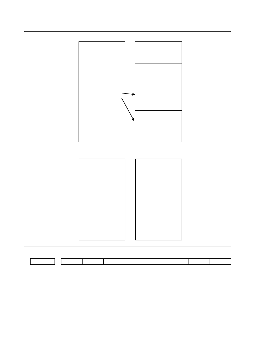
Path 1                   Path 2 


O0100; 

G00 X0.0 Z0.0 ; 

M103 P3 L0 X10.0 Z10.0 ; 

Waiting for (1) 

Path2 begins to wait till 
other path crosses 
coordinate values (X

10.0, 

Z

10.0). 

Path2 keeps waiting 
because the requirement of 
Z axis is not met though 
coordinate value of X axis 
crosses (X

10.0) in block 

(2). 
Path2 begins to execute a 
next block because 
coordinate values crosses 
Z

10.0 on the way of block 

(3). 


O0100; 

G00 X0.0 ; 

G00 Z0.0 ; 

  : 

G00 X50.0 Z50.0 ; 

M103 P3; ....................... (1) 


S1000 M03 ; 

G99 G01 X-30.0 F0.2 ; .. (2) 

Z-30.0 ; .......................... (3) 


L1 command 

Path 1                   Path 2 


O0100; 

G00 X0.0 Z0.0 ; 

M103 P3 L1 X10.0 Z10.0 ;

...................................... 

Waiting for (1) 


Path2 begins to execute a 

next block 


G00 X50.0 Z50.0 ; .........(2) 


O0100; 

G00 X0.0 ; 

G00 Z0.0 ; 

 : 

G00 X50.0 Z50.0 ; 

M103 P3; .......................(1) 


Waiting till other path 

crosses coordinate values 

(X

10.0, Z

10.0) 


Path1 begins to execute a 
next block because 
coordinate values crosses 
(X

10.0, Z

10.0) in the 

middle of block (2). 


Parameter 


#7 

#6 

#5 

#4 

#3 

#2 

#1 

#0 

3104 


DAC 

DAL 


[Input type]  Parameter input 


[Data type]  Bit path 


#6  DAL

  The displayed absolute position is 

0: 

The actual position that takes tool length offset into account. 

1: 

The programmed position that does not take tool length offset into account. 


B-64693EN-1/01


8. MULTI-PATH CONTROL


- 1403 - 

NOTE 

In lathe systems, whether a tool offset is excluded from displaying 
absolute position is determined by the setting of bit 1 (DAP) of 
parameter No.3129. 


#7

  DAC

  When an absolute position are displayed: 

0: 

Values not excluding the amount of travel based on cutter compensation and tool 
nose radius compensation are displayed. 

1: 

Values excluding the amount of travel based on cutter compensation and tool nose 
radius compensation (programmed positions) are displayed. 


NOTE 

When the parameter DAC is set to 1, in the command like circle 
interpolation where the cutter compensation vector is changed 
constantly, an absolute position is not correctly displayed during its 
interpolation except its start point and its end point. 


#7 

#6 

#5 

#4 

#3 

#2 

#1 

#0 

3129 


DAP 


[Input type]  Parameter input 


[Data type]  Bit path 


#1  DAP

  For absolute coordinate display: 

0: 

The actual position including a tool offset (tool movement) is displayed. 

1: 

The programmed position excluding a tool offset (tool movement) is displayed. 


NOTE 

In machining center systems, whether the tool length offset is 
excluded from displaying absolute position is determined according 
to the setting of bit 6 (DAL) of parameter No.3104 


#7 

#6 

#5 

#4 

#3 

#2 

#1 

#0 

8101 


STW 


[Input type]  Parameter input 


[Data type]  Bit path 


#1  STW

  Waiting function by specifying start point is 

0: 

Not effective. 

1: 

Effective.   


8110 


Waiting M code range (minimum value) 


8111 


Waiting M code range (maximum value) 


[Input type]  Parameter input 


[Data type]  2-word 


[Valid data range]  0 ,100 to 99999999 

A range of M code values can be set by specifying a minimum waiting M code value 
(parameter No. 8110) and a maximum waiting M code value (parameter No. 8111). 
 

8. MULTI-PATH CONTROL


B-64693EN-1/01


- 1404 - 

(parameter No. 8110) 


(waiting M code) 


(parameter No. 8111) 

 
Set 0 in these parameters when the waiting M code is not used. 


Signal 

No-wait signal 

NMWT<Gn063.7>(for path individual signal interface) 

  [Classification]  Input signal 
 

[Function]  Specifies whether to synchronize the paths by the waiting M code. 


[Operation]  When this signal turns to "1" the paths are not synchronized by the M code. The M code 

for waiting specified in a machining program is ignored. 
When this signal turns to "0", the paths are synchronized by the M code. When the M 
code for waiting is specified for one path, the next block starts executed after the same M 
code is specified on another path. 


NOTE 

Set all signals NMWT <Gn063.7> to "1" for ignoring the waiting 
when using M code for the waiting function by specifying start 
point. 


Waiting signal 

WATO<F0063.6>(for path common signal interface) 
WATO<Fn063.6>(for path individual signal interface) 

  [Classification]  Output signal 
 

[Function]  Indicates that a waiting M code is being executed. 


[Output cond.]  These signals are "1" as long as: 

One path is waiting for another path. That is, the signal stays "1" for the period from 
when the M code for waiting is issued to one path to when the corresponding M 
code is issued to another path. In addition of the waiting function by specifying start 
point,  the signal stays "1" when one path is waiting for the completion of the axis 
movement. 

This signal is "0" as long as: 

Neither of the paths is waiting for the other. 


Auxiliary function code signals M00 to M31<Fn010 to Fn013> 

  [Classification]  Output signal 
 

[Function]  These signals report that auxiliary functions are specified. 


[Output cond.]  When the waiting function by specifying start point is available, these signals are output 

during waiting for other path M code or the completion of the axis movement. 
 

Signal address 


#7 

#6 

#5 

#4 

#3 

#2 

#1 

#0 

Gn063 


NWMT 


Fn010 


M07 

M06 

M05 

M04 

M03 

M02 

M01 

M00 


Fn011 


M15 

M14 

M13 

M12 

M11 

M10 

M09 

M08 


Fn012 


M23 

M22 

M21 

M20 

M19 

M18 

M17 

M16 


Fn013 


M31 

M30 

M29 

M28 

M27 

M26 

M25 

M24 


Fn063 


WATO 


B-64693EN-1/01


8. MULTI-PATH CONTROL


- 1405 - 

Alarm and message 

Number 

Message 

Description 

PS0003 

TOO MANY DIGIT 

Data entered with more digits than permitted in the NC 
instruction word. 
The number of permissible digits varies according to the 
function and the word. 

PS0009 

IMPROPER NC-ADDRESS


An illegal address was specified, or parameter 1020 is not 
set. 

PS0160 

MISMATCH WAITING M-CODE 

A waiting M-code is in error. 
<1> When different M codes are specified for path 1 and path 

2 as waiting M codes without a P command. 

<2> When the waiting M codes are not identical even though 

the P commands are identical 

<3> When the waiting M codes are identical and the P 

commands are not identical (This occurs when a P 
command is specified with binary value.) 

<4> When the number lists in the P commands contain a 

different number even though the waiting M codes are 
identical (This occurs when a P command is specified by 
combining path numbers.) 

<5> When a waiting M code without a P command (2-path 

waiting) and a waiting M code with a P command were 
specified at the same time 

<6> When the waiting function by specifying start point and a 

waiting M code without a P command (2-path waiting) 
were specified at the same time. 

PS0161 

ILLEGAL P OF WAITING M-CODE 

P in a waiting M-code is incorrect. 
<1> When address P is negative 
<2> When a P value inappropriate for the system 

configuration was specified 


Note 

Inch / metric switching 

Specifying coordinates of the waiting function by specifying start point might be failed when the input   
unit system is changed by G20/G21 during executing program. 


O0100; 

G00 X0. Z0. ; 

M103 P3 L0 X10. Z10. ; . 

(When M103 is executed, 

the other path is a unit of 

metric.) 

Coordinates of a different 

unit are compared because 

the input unit system has 

been changed when 

waiting M code ends.


O0100; 

G20    ; (METRIC) 

G00 X0 Z0. ; 

 : 

G21 ; (INCH) 

G00 X50. Z50. ; 

M103 P3; .......................(1) 

X-30. Z-30. ; ..................(2) 


Current block display 

The start position coordinates are not displayed in the current block display and the next block display of   
the program screen. 
 

Execution macro 

The waiting function by specifying start point cannot be used in execution macro (P-code program). 
Also, macro cannot be called by M code of the waiting function by specifying start point. 
 

8. MULTI-PATH CONTROL


B-64693EN-1/01


- 1406 - 

Manual operation during waiting 

Even if mode of operation is changed to the manual mode during waiting by specifying start position, 
waiting is completed when absolute coordinate value enters the specified area. 
At this time, please change to JOG mode in only a path which axis moves, and please maintain memory 
mode in a path that is waiting. 
 

Repetition of waiting command 

When both of paths command L0, waiting is not completed and halt because each path waits for the 
movement of the other path. 

Path 1)  


Path2) 

M_ P_ L0 X_ Z_ ; Halt 


M_ P_ L0 X_ Z_ ; Halt 

 
When a path command L1 and another path command L0, waiting of a path with L1 is completed and 
executes a next block, however waiting of a path with L0 is not completed and halt. 

Path 1)  


Path2) 

M_ P_ L1 X_ Z_ ; Execute a next block   

M_ P_ L0 X_ Z_ ; Halt 


Amount of tool compensation and current position display 

When the absolute coordinate value of the current position display reaches the start position, waiting is   
completed. Therefore, the start position can be shifted from the program coordinates when the tool   
compensation (wear-out compensation and tool-nose radius compensation etc.) is effective. 
 
Example) 
 

T0101 ; (When the amount wear-out compensation is X = -1.000) 


G00 X0.0 ; 


M103 P3 L1 X10.0 ; 


G00 X20.0 ; 

When bit 6 (DAL) of parameter No. 3104 is 0, waiting is completed when absolute coordinate value 
is X = 10.000 and the amount of distance to go is X = 9.000. 

When bit 6 (DAL) of parameter No. 3104 is 0, waiting is completed when absolute coordinate value 
is X = 10.000 and the amount of distance to go is X = 10.000.   


Manual handle retrace 

Forward movement 
 

There is not any restriction in forward movement. 

 
Backward movement 
 

When this function is effective, manual handle retrace function prohibits changing direction at a 
waiting M code block in backward movement. Continue backward movement until waiting M code 
is appeared in all paths. 


NOTE 

When this function or waiting M code is used with manual handle retrace, please 
set bit 4 (HMP) of parameter No. 6400 to 1 in the both of paths, and when 
inversion or backward movement is inhibited in other path, inversion or backward 
movement is inhibited also for the current executed path. 


Flexible path axis assignment 

Please do not execute flexible path axis assignment when paths are waiting. 
 

Retrace (M system) 

When the waiting function by specifying start point is available, a waiting M code cannot move backward. 
Only forward movement is possible. 

B-64693EN-1/01


8. MULTI-PATH CONTROL


- 1407 - 


Incremental command 

Even if incremental command mode is selected by G91 command in G code system B or C at the path 
where M code for the waiting function by specifying start point is specified, it is assumed that absolute 
coordinate value is specified as a start point. 
If address U, V or W, that are incremental commands, are specified as start point, the alarm PS0009 
occurs. 
 

Rotary axis roll- over 

If a rotary axis which has roll-over function is specified as an axis of start point, this coordinate value, to 
which roll-over function is not applied, is compared with the current absolute coordinate value which is 
rounded by the angle corresponding to one rotation to judge whether a condition for waiting is met. 
 
Example) 
The axis A is the rotary axis and the amount of movement per rotation is 360.000   
(Parameter No. 1260 = 360.000) 
 
N10 G00 A0.0 ; 
N20 M100 P3 L1 A180.0 ; 
N30 G00 A-10.0 ; 
 
After  the end of N30 block, the absolute coordinate value of A axis is 350.0. Therefore, because this 
value becomes A

180.0 in the middle of this block, waiting is completed. 


8.16 

FUNCTION FOR LOADER CONTROL 

Overview 

The function for loader control is used to control the devices for performing a non-machining operation 
(peripheral device such as a loader). When this function is valid, the path for performing a loader control 
is added besides a path for machining. 
(In the subsequent explanation, the path which applies the function for loader control is called the loader 
path, while the other path is called the machining path.) 
 

Explanation 

System configuration 

When the function for loader control is valid, a combination of paths is as follows. 

Machining path 1 + Loader path 1 
Machining path 1 + Loader path 1 + Loader path 2 
Machining path 1 + Machining path 2 + Loader path 1 
Machining path 1 + Machining path 2 + Loader path 1 + Loader path 2 
Machining path 1 + Machining path 2 + Machining path 3 + Loader path 2 

 
Loader paths follow machining paths. When a number of machining paths is only 1, loader paths are 
added as the second or later path. When a number of machining paths is 2, loader paths are added as the 
third or later path. Loader path can be added up to 2 paths, but the total number of machining paths and 
loader paths cannot exceed 4. 
 

8. MULTI-PATH CONTROL


B-64693EN-1/01


- 1408 - 


Machining 

path2 

(2nd path) 

Axis


Axis


Machining 

path1 

(1st path) 

Axis


Axis


Loader path1 


(3rd path) 

Axis


Axis


Machining 

path1 

(1st path) 

Axis


Axis


Machining 

path2 

(2nd path) 

Axis


Axis


Loader path1 


(3rd path) 

Axis


Axis


Loader path2 


(4th path) 

Axis


Axis


Machining 

path1 

(1st path) 

Axis


Axis


Machining 

path2 

(2nd path) 

Axis


Axis


Machining 

path3 

(3rd path) 


Axis


Axis


Loader path1 


(4th path) 

Axis


Axis


Machining 

path1 

(1st path) 

Axis


Axis


Loader path1 


(2nd path) 

Axis


Axis


Loader path1 


(2nd path) 

Axis


Axis


Loader path2 


(3rd path) 

Axis


Axis


Machining 

path1 

(1st path) 

Axis


Axis


NOTE 

1  To use the loader path 2, the addition of loader control path option is required in 

addition to the function for loader control option. 

2  The function for loader control cannot be used in the system with more than 4 

machining paths. 


Machine control type 

When lathe system is specified as the machine control type, all paths including loader paths are controlled 
as a lathe. When machining  center system is also specified as same, all paths are controlled as a 
machining center. When combined system is specified, each path can be selected either lathe system or 
machining center system. Select either type for a loader path. 
 

Machine group 

A machine group is available on a loader path. Up to 3 groups are available, depending on the type of the 
CNC system. 
 
Example) 


CNC unit


1st machine group 

2nd machine group 


3rd machine group 


Machining


path1 

Axis


Axis


Machining 

path2 

Axis


Axis


Loader


path1 

Axis


Axis


Loader


path2 

Axis


Axis


Number of feed axes 

The maximum number of feed axes for the loader path is 4. However, when there are 2 loader paths, the 
maximum number of feed axes is 3 per path. When a controlled axis is assigned to a loader path, the 
absolute path number of a loader path is set to parameter No.981. 
 
Example 1) 
 

For a system with 2 paths and a total of 6 controlled axes: 


Settings that cause the system to become a 2-path system with the machining path 1 consisting of 3 
controlled axes and the loader path 1 consisting of 3 controlled axes. 

Setting value of parameter No. 0981 

Application 

Machining path 1 (1st path), axis 1 

Machining path 1 (1st path), axis 2 

B-64693EN-1/01


8. MULTI-PATH CONTROL


- 1409 - 

Setting value of parameter No. 0981 

Application 

Machining path 1 (1st path), axis 3 

Loader path 1 (2nd path), axis 1 

Loader path 1 (2nd path), axis 2 

Loader path 1 (2nd path), axis 3 

 
Example 2) 
 

For a system with 4 paths and a total of 10 controlled axes: 


Settings that cause the system to become a 4-path system with the machining path 1 consisting of 3 
controlled axes, the machining path 2 consisting of 3 controlled axes, the loader path 1 consisting of 
2 controlled axes and the loader path 2 consisting of 2 controlled axes. 

Setting value of parameter No. 0981 

Application 

Machining path 1 (1st path), axis 1 

Machining path 1 (1st path), axis 2 

Machining path 1 (1st path), axis 3 

Machining path 2 (2nd path), axis 1 

Machining path 2 (2nd path), axis 2 

Machining path 2 (2nd path), axis 3 

Loader path 1 (3rd path), axis 1 

Loader path 1 (3rd path), axis 2 

Loader path 2 (4th path), axis 1 

Loader path 2 (4th path), axis 2 


Designation of spindle axes 

The loader path does not have a spindle. When the loader path is specified in a parameter No.982, which 
specifies the path to which each spindle belongs, alarm PS0365, “TOO MANY MAXIMUM SV/SP 
AXIS NUMBER PER PATH” is issued. 
 

Part program storage size / Number of registerable programs 

A part program storage size and a number of registerable programs for the loader path are included in 
them of an entire system. Even when the loader path is added, part program storage size / number of 
registerable programs of an entire system do not change. 
 

DI/DO 

The DI/DO specifications of the loader path confirm to the DI/DO specifications in multi-path control. In 
the loader path also, therefore, create a ladder program with the same interface as that for the machining 
path. Addresses of signals for a loader path are as follows. 
 

In case that a number of machining path is only 1: 


Loader path 1: F1000 to F1767, G1000 to G1767 (the 2nd path in the entire system) 


Loader path 2: F2000 to F2767, G2000 to G2767 (the 3rd path in the entire system) 


In case that a number of machining path is 2: 


Loader path 1: F2000 to F2767, G2000 to G2767 (the 3rd path in the entire system) 


Loader path 2: F3000 to F3767, G3000 to G3767 (the 4th path in the entire system) 


In case that a number of machining path is 3: 


Loader path 1: F3000 to F3767, G3000 to G3767 (the 4th path in the entire system) 


Path selection 

When  the loader control selection signal LCBS <G0251.1> turns to "1", the reference destination of 
screen display and MDI operation are switched to a loader path. If the loader path 2 exists, when  the 
loader control 2 selection signal LCB2 <G0251.2> turns to "1", the loader path 2 is subjected to screen 
display or MDI operation. 


Content      ..     179      180      181      182     ..