FANUC Series 0i-MODEL F Plus. CONNECTION MANUAL (FUNCTION) - page 127
 

  Index      Manuals     FANUC Series 0i-MODEL F Plus. CONNECTION MANUAL (FUNCTION) B-64693EN-1/01


Search            copyright infringement  


Content      ..     125      126      127      128     ..


FANUC Series 0i-MODEL F Plus. CONNECTION MANUAL (FUNCTION) - page 127


6. INTERPOLATION FUNCTION


B-64693EN-1/01


- 970 - 


(Example) 

When one-shot G60 commands are used. 

When modal G60 command is used. 


G90; 


G90 G60; 

Single direction positioning mode start 

G60 X0 Y0; 


X0 Y0; 


G60 X100; 

Single direction positioning 

X100; 

Single direction positioning 

G60 Y100; 


Y100; 


G04 X10; 


G04 X10; 

G00 X0 Y0; 


G00 X0 Y0; 

Single direction positioning mode cancel 


  - 

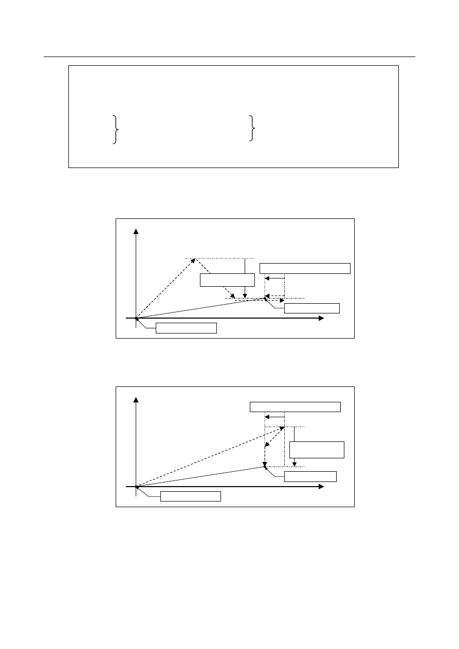
Overview of operation 

In the case of positioning of non-linear interpolation type (bit 1 (LRP) of parameter No. 1401 = 
0) 


As shown Fig. 6.2(b), single direction positioning is performed independently along each axis. 


Programmed end point 

Programmed start point 

Overrun distance in the 
X-axis direction 

Overrun distance in the Z-axis direction 


Fig. 6.2 (b) 


In the case of positioning of linear interpolation type (bit 1 (LRP) of parameter No. 1401 = 1) 


Positioning of interpolation type is performed until the tool once stops before or after a specified end 
point. Then, the tool is positioned independently along each axis until the end point is reached. 


Programmed end point 

Programmed start point 

Overrun distance in the 
X-axis direction 

Overrun distance in the Z-axis direction 


Fig. 6.2 (c) 


B-64693EN-1/01


6. INTERPOLATION FUNCTION


- 971 - 

Parameter 


#7 

#6 

#5 

#4 

#3 

#2 

#1 

#0 

5431 


PDI 

MDL 


[Input type]  Parameter input 


[Data type]  Bit 


#0  MDL

  The G60 code (single direction positioning) is: 

0: 

One-shot G code (group 00). 

1: 

Modal G code (group 01). 


#1  PDI

  In the G60 mode, an in-position check at a stop position is: 

0: 

Not made. (Waiting for only the end of acceleration/deceleration) 

1: 

Made. 


5440 


Positioning direction and overrun distance in single direction positioning 


[Input type]  Parameter input 


[Data type]  Real axis 


[Unit of data]  mm, inch, deg (machine unit) 

[Min. unit of data]  Depend on the increment system of the applied axis 
[Valid data range]  Refer to the standard parameter setting table (A) 

(When the increment system is IS-B, -999999.999 to +999999.999) 
This parameter sets the positioning direction and overrun distance in single direction 
positioning (G60) for each axis. The positioning direction is specified using a setting data 
sign, and the overrun distance using a value set here. 
Overrun distance>0: The positioning direction is positive (+). 
Overrun distance<0: The positioning direction is negative (-). 
Overrun distance=0: Single direction positioning is not performed. 
 

Alarm And message 

Number 

Message 

Contents 

DS0025 

G60 CANNOT BE EXECUTED


The state of mirror image when a single direction positioning 
block is looked ahead differs from the state of mirror image 
when the execution of the block is started, so that single 
direction positioning cannot be executed. 
Correct the program.   


Limitation 

Single direction positioning is not performed along an axis for which no overrun distance is set in 
parameter No. 5440. 

Single direction positioning is not performed along an axis for which travel distance 0 is specified. 

The mirror image  function is not applied in a parameter-set direction. Even in the mirror image 
mode, the direction of single direction positioning remains unchanged. If positioning of linear 
interpolation type is used, and the state of mirror image when a single direction positioning block is 
looked ahead differs from the state of mirror image when the execution of the block is started, an 
alarm  (DS0025)”G60 CANNOT BE EXECUTED”  is issued. When switching mirror image in the 
middle of a program, disable looking ahead by specifying a non-buffering M code. Then, switch 
mirror image when there is no look-ahead block.   

In the cylindrical interpolation mode (G07.1), single direction positioning cannot be used.   

In the polar coordinate interpolation mode (G12.1), single direction positioning cannot be used. 

6. INTERPOLATION FUNCTION


B-64693EN-1/01


- 972 - 

When specifying single direction positioning on a machine that uses angular axis control, first 
position the angular axis then specify the positioning of the Cartesian axis. If the reverse 
specification order is used, or the angular axis and Cartesian axis are specified in the same block, an 
incorrect positioning direction can result. 

In positioning at a restart position by program restart function, single direction positioning is not 
performed. 


M


Single direction positioning cannot be performed for a hole machining axis in a canned cycle for 
hole machining.   

Single direction positioning is not performed for an axis subject to shift value movement in a G76 or 
G87 canned cycle.   


T


The G code for single direction positioning is G60, regardless of whether the G code system is A, B, 
or C. 

In a multiple repetitive canned cycle (G70 to G76), single direction positioning cannot be used. 

Single direction positioning cannot be used for a hole machining axis in a canned cycle for hole 
machining (G83 to G89) and rigid tapping (G84 and G88). However, single direction positioning 
can be used for positioning operation. 

Single direction positioning cannot be used in a canned cycle (G90, G92, or G94). 

In the single direction positioning mode, G07.1, G12.1, G70 to G76, and G90 to G94 cannot be 
specified. 


Reference item 

Manual name 

Item name 

OPERATOR’S MANUAL (B-64694EN) 

Single direction positioning 


6.3 

LINEAR INTERPOLATION 

Overview 

Tools can move along a line. A tools move along a line to the specified position at the feedrate specified 
in F. 
The feedrate specified in F is effective until a new value is specified. It need not be specified for each 
block. 
The feedrate commanded by the F code is measured along the tool path. If the F code is not commanded, 
the feedrate is regarded as zero. 
The feedrate of each axis direction is as follows. 
 

G01 

α

α


β

β


γ

γ


ζ

ζ

 ; 

Feed rate of 

α

 axis direction : F

α

=

α

/L

×

Feed rate of 

β

 axis direction : F

β

=

β

/L

×

Feed rate of 

γ

 axis direction : F

γ

=

γ

/L

×

Feed rate of 

ζ

 axis direction : F

ζ

=

ζ

/L

×

2

2

2

2

ζ

γ

β

α

+

+

+

=

L


The feedrate of the rotary axis is commanded in the unit of deg/min (if the feedrate is 12 deg/min, F12.0 
is commanded). 
When the straight line axis 

α

 (such as X, Y, or Z) and the rotating axis 

β

 (such as A, B, or C) are linearly 

interpolated, the feed rate is that in which the tangential feed rate in the 

α

  and 

β

  cartesian coordinate 

system is commanded by F(mm/min).   

B-64693EN-1/01


6. INTERPOLATION FUNCTION


- 973 - 

β

-axis feedrate is obtained ; at first, the time required for distribution is calculated by using the above 

formula, then the 

β

-axis feedrate unit is changed to deg/min. 

A calculation example is as follows. 
(Example) 

G91 G01 X20.0 C40.0 F300.0 ; 
This changes the unit of the C axis from 40.0 deg to 40mm with metric input. The time required for 
distribution is calculated as follows: 

300

2

40

2

20

+

min

14907

.

0


The feed rate for the C axis is 

min

14907

.

0

deg

40

in

268.3deg/m


In simultaneous 3 axes control, the feed rate is calculated in cartesian coordinate system the same way as 
in simultaneous 2 axes control. 
 

Parameter 

1411 


Cutting feedrate 


NOTE 


When this parameter is set, the power must be turned off before 
operation is continued. 


[Input type]  Setting input 


[Data type]  Real path 


[Unit of data]  mm/min, inch/min, deg/min (input unit) 

[Min. unit of data]  Depend on the increment system of the reference axis 
[Valid data range]  Refer to the standard parameter setting table (C) 

(When the increment system is IS-B, 0.0 to +999000.0) 
A cutting feedrate can be specified with this parameter for a machine which does not have 
to change the cutting feedrate frequently  during machining. This eliminates the need to 
specify a cutting feedrate (F code) in the NC program. 
 

1430 


Maximum cutting feedrate for each axis 


[Input type]  Parameter input 


[Data type]  Real axis 


[Unit of data]  mm/min, inch/min, deg/min (machine unit) 

[Min. unit of data]  Depend on the increment system of the applied axis 
[Valid data range]  Refer to the standard parameter setting table (C) 

(When the increment system is IS-B, 0.0 to +999000.0) 
Specify the maximum cutting feedrate for each axis. 


#7 

#6 

#5 

#4 

#3 

#2 

#1 

#0 

3402 


G01 


[Input type]  Parameter input 


[Data type]  Bit path 


#0  G01

  G01 Mode entered when the power is turned on or when the control is cleared 

0: 

G00 mode (positioning) 

1: 

G01 mode (linear interpolation) 

6. INTERPOLATION FUNCTION


B-64693EN-1/01


- 974 - 


Alarm and message 

Number 

Message 

Description 

PS0011 

FEED ZERO (COMMAND) 

The cutting feedrate instructed by an F code has been set to 0. 
This alarm is also generated if the F code instructed for the S code is set 
extremely small in a rigid tapping instruction as the tool cannot cut at the 
programmed lead. 


Reference item 

Manual name 

Item name 

OPERATOR’S MANUAL (B-64694EN) 

Linear interpolation (G01) 


6.4 

CIRCULAR INTERPOLATION 

Overview 

The command below can move a tool along a circular arc in the defined plane. 
"Clockwise"(G02) and "counterclockwise"(G03) on the XpYp plane (ZpXp plane or YpZp plane) are 
defined when the XpYp plane is viewed in the positive-to-negative direction of the Zp axis (Yp axis or 
Xp axis, respectively) in the right-handed Cartesian coordinate system. See the Fig. 6.4 (a). 


Yp 

G02 

G03 

Xp 

G17 

G18 

G19 

G02 

G03 

Zp 

G02 

G03 

Yp 

Xp 

Zp 


Fig. 6.4 (a) 

 
The end point of an arc is specified by address Xp, Yp or Zp, and is expressed as an absolute or 
incremental value according to G90 or G91. For the incremental value, the distance of the end point 
which is viewed from the start point of the arc is specified with a sign. 
The arc center is specified by addresses I, J, and K for the Xp, Yp, and Zp axes, respectively. The 
numerical value following I, J, or K, however, is a vector component in which the arc center is seen from 
the start point, and is always specified as an incremental value, as shown below (Fig. 6.4 (b)). 
I, J, and K must be signed according to the direction. 


End point 
(x,y) 


Center 


Center 


Center 


Start 
point 


Start 
point 


End point   
(z,x) 


End point   
(y,z) 


Start 
point 


Fig. 6.4 (b) 

 
I0,J0, and K0 can be omitted. When Xp, Yp , and Zp are omitted (the end point is the same as the start 
point) and the center is specified with I, J, and K, a 360

°

 arc (circle) is specified. 

G02 I; Command for a circle 
If the difference between the radius at the start point and that at the end point exceeds the value in a 
parameter No. 3410, an alarm PS0020 occurs. 
The distance between an arc and the center of a circle that contains the arc can be specified using the 
radius, R, of the circle instead of I, J, and K. 
In this case, one arc is less than 180

°

, and the other is more than 180

°

 are considered. 

B-64693EN-1/01


6. INTERPOLATION FUNCTION


- 975 - 

Specify an arc more than 180

°

 with a negative radius value commanded. 

If Xp, Yp, and Zp are all omitted, if the end point is located at the same position as the start point and 
when R is used, an arc of 05 is programmed. 
G02R_ ; (The tool does not move.) 


(Example) 
For arc (1) (less than 180

°

G91 G02 X60.0 Y20.0 R50.0 F300.0 ; 
For arc (2) (greater than 180

°

G91 G02 X60.0 Y20.0 R-50.0 F300.0 ; 


r=50mm 


End point 


Start point 


r=50mm 


(1) 


(2) 


Fig. 6.4 (c) 

 
The feedrate in circular interpolation is equal to the feedrate specified by the F code, and the feedrate 
along the arc (the tangential feedrate of the arc) is controlled to be the specified feedrate. 


Parameter 

1022 


Setting of each axis in the basic coordinate system 


[Input type]  Parameter input 


[Data type]  Byte axis 

[Valid data range]  0 to 7 

To determine a plane for circular interpolation, cutter compensation, and so forth (G17: 
Xp-Yp  plane,  G18:  Zp-Xp  plane,  G19:  Yp-Zp  plane),  specify  which of the basic three 
axes (X, Y, and Z) is used for each control axis, or a parallel axis of which basic axis is 
used for each control axis. 
A basic axis (X, Y, or Z) can be specified only for one control axis. 
Two or more control axes can be set as parallel axes for the same basic axis. 

Table 6.4 (a) 

Setting 

Meaning 

Rotary axis (Neither the basic three axes nor a parallel axis) 

X axis of the basic three axes 

Y axis of the basic three axes 

Z axis of the basic three axes 

Axis parallel to the X axis 

Axis parallel to the Y axis 

Axis parallel to the Z axis 

 
In general, the increment  system  and diameter/radius specification  of an axis  set as a 
parallel axis are to be set in the same way as for the basic three axes. 
 

6. INTERPOLATION FUNCTION


B-64693EN-1/01


- 976 - 


#7 

#6 

#5 

#4 

#3 

#2 

#1 

#0 

3402 


G19 

G18 


[Input type]  Parameter input 


[Data type]  Bit path 


#1  G18

  Plane selected when power is turned on or when the control is cleared 

0: 

G17 mode (plane XY) 

1: 

G18 mode (plane ZX) 


#2  G19

  Plane selected when power is turned on or when the control is cleared 

0: 

The setting of bit 1 (G18) of parameter No. 3402 is followed. 

1: 

G19 mode (plane YZ) 

When this bit is set to 1, set bit 1 (G18) of parameter No. 3402 to 0. 
 

3410 


Tolerance of arc radius 


[Input type]  Setting input 


[Data type]  Real path 


[Unit of data]  mm, inch (input unit) 

[Min. unit of data]  Depend on the increment system of the reference axis 
[Valid data range]  0 or positive 9 digit of minimum unit of data (refer to the standard parameter setting table 

(B)) 
(When the increment system is IS-B, 0.0 to +999999.999) 
When a circular interpolation command is executed, the tolerance for the radius between 
the start point and the end point is set. 
 

Alarm and message 

Number 

Message 

Description 

PS0011 

FEED ZERO (COMMAND) 

The cutting feedrate instructed by an F code has been set to 0. 
This alarm is also generated if the F code instructed for the S code is set 
extremely small in a rigid tapping instruction as the tool cannot cut at the 
programmed lead. 

PS0020 

OVER TOLERANCE OF 
RADIUS 

An arc was specified for which the difference in the radius at the start 
and end points exceeds the value set in parameter No. 3410. Check arc 
center codes I, J and K in the program. 
The tool path when parameter No. 3410 is set to a large value is spiral. 

PS0021 

ILLEGAL PLANE SELECT 

1) In the selected plane (by G17, G18 or G19 command), the basic 

axis(X,Y, or Z) and its parallel axis are commanded at the same 
time. Modify the program. 

2) In the following functions, an axis not included in the selected plane 

was commanded,or the selected plane was not correct. Modify the 
program : 

    - Circular interpolation   
    - Multiple repetitive cycle (if parameter DSA(No.5109#0) is set to 1.)   
    etc. 
3)  In the helical interpolation, the number of axes that can be 

commanded simultaneously is exceeded. 


Modify the program. 

PS0025 

CIRCLE CUT IN RAPID 
(F0) 

F0 (rapid traverse in inverse feed or feed specified by an F code with 
1–digit number) was specified during circular interpolation (G02, G03). 


B-64693EN-1/01


6. INTERPOLATION FUNCTION


- 977 - 

Note 

NOTE 

1  For T series, the U, V and W axes (parallel with the basic axis) can be used with 

G-code system B and C. 

2  If I, J, K, and R addresses are specified simultaneously, the arc specified by 

address R takes precedence and the other are ignored. 

3  If an axis not comprising the specified plane is commanded, an alarm is 

displayed. 


For example, when G code system B or C is used, if U axis with X axis is 
specified as a parallel axis to X axis when plane XY is specified, an alarm 
PS0021 is displayed. 


Reference item 

Manual name 

Item name 

OPERATOR’S MANUAL (B-64694EN) 

Circular interpolation (G02, G03) 


6.5 

THREADING 

6.5.1 

Threading 

Overview 

Tool movement can be synchronized with spindle rotation when cutting threads. 
The spindle speed is continuously read through the position coder attached to the spindle. Then, it is 
converted to a cutting feedrate (feed per minute) to feed the tool. 


Straight thread 


Tapered Screw 


Scroll Thread 


L : Lead 


Fig. 6.5.1 (a) 

 
In general, thread cutting is repeated along the same tool path in rough cutting through finish cutting for a 
screw. Since thread cutting starts when the position coder mounted on the spindle outputs a 1-turn signal, 
threading is started at a fixed point and the tool path on the workpiece is unchanged for repeated thread 
cutting. Note that the spindle speed must remain constant from rough cutting through finish cutting. If not, 
incorrect thread lead will occur. 
 

  CAUTION 


Detector with one-rotation signal is required for threading, and it must be 
connected with spindle at a gear ratio of 1:1.   
If detector is not connected correctly, the lead of threading may become wrong or 
start position of threading may become wrong. 


Content      ..     125      126      127      128     ..