FANUC Series 0i-MODEL F Plus. CONNECTION MANUAL (FUNCTION) - page 84
 

  Index      Manuals     FANUC Series 0i-MODEL F Plus. CONNECTION MANUAL (FUNCTION) B-64693EN-1/01


Search            copyright infringement  


Content      ..     82      83      84      85     ..


FANUC Series 0i-MODEL F Plus. CONNECTION MANUAL (FUNCTION) - page 84


3. MANUAL OPERATION


B-64693EN-1/01


- 626 - 


Time 


T

j


T

j


T

j


Feedrate in manual handle feed 

Feedrate in jog feed 


T

j

 : Const time of jog feed 


Feedrate 


T

j


(1) Jog feed 


(2) Manual handle feed 


Fig.3.2.1 (e)  Switch from the jog feed to the manual handle feed (when RT<Gn019.7> is "0") 


Time 


T

m


T

m


Feedrate in manual rapid traverse 


T

m

 : Const time of rapid traverse 


Feedrate in manual handle feed 


T

m


Feedrate 


T

m


(1) Manual rapid traverse 


(2) Manual handle feed 


Fig.3.2.1 (f)  Switch from the jog feed to the manual handle feed (when RT<Gn019.7> is "1") 


  - 

Prohibition of superimposed feed of the jog feed and the manual handle feed 
(Bit 1 (FJH) of parameter No. 7107) 

When  bit 1 (FJH) of  parameter  No. 7107 is set to 1,  the jog feed and the manual handle feed are not 
superimposed. Priority can be placed on the jog feed if both are executed at the same time. 
 
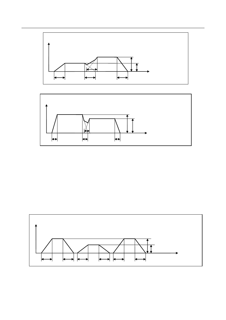
Fig. 3.2.1 (g) and (h) show the operation which commanded in the following order in JOG mode. 
(1) Manual handle feed 
(2) Jog feed 
(3) Manual handle feed 
When manual rapid traverse selection signal RT <Gn019.7> is set to "0", the  type of 
acceleration/deceleration and the time constant in jog feed and manual handle feed are those of jog feed. 


Time 


T

j


T

j


T

j


Feedrate in manual handle feed 

Feedrate in jog feed 

T

j

 : Const time of jog feed 

T

j


T

j


T

j


Feedrate 


(1) Manual handle feed 


(2) Jog feed 


(3) Manual handle feed 


Fig. 3.2.1 (g)  Switch of the jog feed and the manual handle feed (when RT<Gn019.7> is "0") 

 
When manual rapid traverse selection signal RT <Gn019.7> is set to "1", the type of 
acceleration/deceleration and the time constant in jog feed are those of rapid traverse, the type of 
acceleration/deceleration and the time constant in manual handle feed are those of jog feed. 
 

B-64693EN-1/01


3. MANUAL OPERATION


- 627 - 


Time 


T

j


T

j


Feedrate of manual handle feed 

Feedrate in manual rapid traverse 

T

j

 : Const time of jog feed 

T

m

 : Const time of rapid traverse 

T

m


T

m


T

j


T

j


Feedrate 


(1) Manual handle feed 


(2) Manual rapid traverse 


(3) Manual handle feed 


Fig. 3.2.1 (h)  Switch of the jog feed and the manual handle feed (when RT<Gn019.7> is "1") 

 
Fig.3.2.1  (i)  and (j) show the operation which started (2) manual handle feed immediately after (1) jog 
feed. 
The type of acceleration/deceleration and the time constant are  switched after checking that delay in 
acceleration/deceleration is 0. 


Time 


T

j


T

j


T

j


Feedrate in manual handle feed 


Feedrate in jog feed 

Feedrate 


T

j


T

j

 : Const time of jog feed 


(1) Jog feed 


(2) Manual handle feed 


Fig.3.2.1 (i)  Switch from the jog feed to the manual handle feed (when RT<Gn019.7> is "0") 


Time 

T

j


T

j


T

m


T

m


Feedrate in manual rapid traverse 


T

m

 : Const time of rapid traverse 

Feedrate in manual handle feed 

T

j

 : Const time of jog feed 

Feedrate 


(1) Manual rapid raverse 


(2) Manual handle feed 


Fig.3.2.1 (j)  Switch from the jog feed to the manual handle feed (when RT<Gn019.7> is "1") 


TEACH IN JOG mode 

When bit 1 (THD) of parameter No.7100 is set to 1, manual handle can be effective in TEACH IN JOG 
mode. Bit 1 (FJH) of parameter No.7107 is effective in this case. 
 

3. MANUAL OPERATION


B-64693EN-1/01


- 628 - 

Parameter 


#7 

#6 

#5 

#4 

#3 

#2 

#1 

#0 

7100 


THD 

JHD 


[Input type]  Parameter input 


[Data type]  Bit path 


#0  JHD

  Manual handle feed in JOG feed mode or incremental feed in the manual handle feed is: 

0: 

Invalid. 

1: 

Valid. 


#1  THD

  In the TEACH IN JOG mode, the manual pulse generator is: 

0: 

Disabled. 

1: 

Enabled. 


#7 

#6 

#5 

#4 

#3 

#2 

#1 

#0 

7107 


FJH 


[Input type]  Parameter input 


[Data type]  Bit 


#1  FJH

  When bit 0 (JHD) of parameter No. 7100 is 1, jog feed and manual handle feed in jog 

feed mode, or incremental feed and manual handle feed in manual handle feed are: 
0: 

superimposed. The type of acceleration/deceleration and the time constant in manual 
handle feed are the type of acceleration/deceleration and the time constant in 
previous commanded feed (either jog feed or manual rapid traverse). 

1: 

not superimposed. Priority can be placed on jog feed or incremental feed if they and 
manual handle feed are executed at the same time. If there is an axis for jog feed or 
incremental feed even for one axis in the path, handle feed is invalid for all axes in 
the path. The type of acceleration/deceleration and the time constant in manual 
handle feed are always those of jog feed. 


NOTE 


When bit 1 (THD) of parameter No.7100 is set to 1, this parameter is 
effective to jog feed and manual handle feed in TEACH IN JOG 
mode. 


Notes 

1)  Axis moving signals MVx<Fn102> of axes that manual handle feed is effective become "1". When bit 

1 (FJH) of parameter No. 7107 is set to 1, even if the manual handle is allocated in axes other than the 
jog feed axes, the signals MVx<Fn102> of those axes does not become "1"  because manual handle 
feed of those axes is not effective. When the manual handle feed become effective after checking that 
delay in acceleration/deceleration is 0, the signals MVx<Fn102> become "1". 


B-64693EN-1/01


3. MANUAL OPERATION


- 629 - 


  Example of timing diagram of MVx<Fn102> when bit 1 (FJH) of parameter No. 7107 is 1 

    Jog feed with X axis is executed when the manual handle is allocated in X axis and Y axis. 


Manual handle feed axis selection 


signals (1st manual pulse generator)   

(assigned to X axis) 


Manual handle feed axis selection 


signals (2nd manual pulse generator)   

(assigned to Y axis) 


Jog feed 

Feed axis and direction selection 


signal (X axis) 


Axis moving signal (X axis) 


Axis moving signal (Y axis) 


Feedrate (X axis) 


*Above-mentioned timing that Axis moving signal becomes "1" after jog feed is one example. 

That is different according to the specified speed and the in-position width. 

Becoming "0" because the manual 

handle feed is disabled 

Keeping "1" because 

of the jog feed 

When 

acceleration/deceleration 

delay is eliminated, handle 

is effective and axis moving 

signal becomes "1" 


3.3 

MANUAL HANDLE INTERRUPT 

Overview 

In the automatic operation mode (manual data input, DNC operation, or memory operation) or memory 
edit mode, by rotating the manual pulse generator, handle feed can be performed by superimposing on the 
movement by automatic operation. The axis to which the handle interrupt is applied is selected using the 
manual handle interrupt axis selection signal. The minimum travel distance per graduation is the least 
command increment. The distance can be scaled by one of four types of magnification that is selected 
using manual handle feed movement selection signals MP1 and MP2 <Gn019 .4 and .5>. 
The scaled distance can be multiplied by 10 using bit 3 (HIT) of parameter No. 7103. Each scale factor 
can be selected using the manual handle travel distance selection signals (refer to "Manual Handle Feed"). 


  WARNING 


The amount of movement per graduation for manual handle interrupt is equal to 
the least input increment like that for manual handle feed. For example, for 
metric input on an inch machine, the tool moves by 0.01 inches for 254 
graduations; for inch input on a millimeter machine, it moves by 0.254 mm for 
100 graduations. 


3. MANUAL OPERATION


B-64693EN-1/01


- 630 - 

Signal 

Manual Handle Interrupt Axis Selection Signals 
 

HS1IA to HS1ID<Gn041.0 to 3>, HS1IE<Gn411.4> 


HS2IA to HS2ID<Gn041.4 to 7>, HS2IE<Gn411.5> 


HS3IA to HS3ID<Gn042.0 to 3>, HS3IE<Gn411.6> 


HS4IA to HS4ID<Gn088.4 to 7>, HS4IE<Gn411.7> 


HS5IA to HS5ID<Gn379.4 to 7>, HS5IE<Gn412.4> 

  [Classification]  Input signal 
 

[Function]  These signals select an axis to which the  manual handle interrupt is applied. There are 

five sets of signals, each corresponding to a manual pulse generator (up to five). Each set 
consists of five code signals A, B, C, D and E. The number in the signal name indicates 
the number of the manual pulse generator to be used. 
HSxIA 
x :  1 

Selects the axis for which manual pulse generator No. 1 is used 


Selects the axis for which manual pulse generator No. 2 is used 


Selects the axis for which manual pulse generator No. 3 is used 


Selects the axis for which manual pulse generator No. 4 is used 


Selects the axis for which manual pulse generator No. 5 is used 

The correspondence between code signals A, B, C, D, and E and selected feed axes is 
similar to the correspondence of the manual handle feed axis  selection signals. See 
"Manual Handle Feed Axis Selection signals." 


Signal address 


#7 

#6 

#5 

#4 

#3 

#2 

#1 

#0 

Gn041 


HS2ID 

HS2IC 

HS2IB 

HS2IA 

HS1ID 

HS1IC 

HS1IB 

HS1IA 


Gn042 


HS3ID 

HS3IC 

HS3IB 

HS3IA 


Gn088 


HS4ID 

HS4IC 

HS4IB 

HS4IA 


Gn379 


HS5ID 

HS5IC 

HS5IB 

HS5IA 


Gn411 


HS4IE 

HS3IE 

HS2IE 

HS1IE 


Gn412 


HS5IE 


Parameter 

1466 


Feedrate for retraction in threading cycle G92 or G76 


Feedrate for retraction in threading cycle G76.7 


[Input type]  Parameter input 


[Data type]  Real path 


[Unit of data]  mm/min, inch/min (machine unit) 

[Min. unit of data]  Depend on the increment system of the reference axis 
[Valid data range]  Refer to the standard parameter setting table (C) 

(When the increment system is IS-B, 0.0 to +999000.0) 
When threading cycle  G92, G76 or G76.7 is specified, retraction is performed  after 
threading. Set a feedrate for this retraction. 


WARNING 


When the manual handle interruption is valid, set the same value 
as the parameter No.1430 to the parameter No.1466. 


B-64693EN-1/01


3. MANUAL OPERATION


- 631 - 

NOTE 


When this parameter is set to 0 or bit 1 (CFR) of parameter No. 
1611 is set to 1, the rapid traverse rate set in parameter No. 1420 
is used. 


#7 

#6 

#5 

#4 

#3 

#2 

#1 

#0 

1606 


MNJx 


[Input type]  Parameter input 


[Data type]  Bit axis 


#0  MNJx

  In manual handle interrupt or automatic manual simultaneous operation (interrupt type): 

0: 

Only  cutting  feed  acceleration/deceleration  is enabled, and jog feed 
acceleration/deceleration is disabled. 

1: 

Both cutting  feed  acceleration/deceleration  and jog feed acceleration/deceleration 
are applied. 


#7 

#6 

#5 

#4 

#3 

#2 

#1 

#0 

6004 


VHD 


[Input type]  Parameter input 


[Data type]  Bit path 


#2  VHD

  With system variables #5121 to #5140: 

0: 

The tool offset value (geometry offset value) in the block currently being executed is 
read. (This parameter is valid only when tool geometry/tool wear compensation 
memories are available.) 

1: 

An interrupt travel distance based on manual handle interrupt is read. 


#7 

#6 

#5 

#4 

#3 

#2 

#1 

#0 

7100 


HCL 


[Input type]  Parameter input 


[Data type]  Bit path 


#3  HCL

  The clearing of handle interruption amount display by soft key [INTRPT  CANCEL] 

operation is: 
0: 

Disabled. 

1: 

Enabled. 


#7 

#6 

#5 

#4 

#3 

#2 

#1 

#0 

7102 


HNGx 


[Input type]  Parameter input 


[Data type]  Bit axis 


#0  HNGx

  Axis movement direction for rotation direction of manual pulse generator 

0: 

Same in direction 

1: 

Reverse in direction 


3. MANUAL OPERATION


B-64693EN-1/01


- 632 - 


#7 

#6 

#5 

#4 

#3 

#2 

#1 

#0 

7103 


HIT 


RTH 


[Input type]  Parameter input 


[Data type]  Bit path 


#1  RTH

  By a reset or emergency stop, the amount of manual handle interruption is: 

0: 

Not canceled. 

1: 

Canceled. 


#3  HIT

  When compared with the travel distance magnification selected by the manual handle 

feed travel distance selection signals (incremental feed signals MP1, MP2  <Gn019.4, 
Gn019.5>), the travel distance magnification for manual handle interrupt is: 
0: 

Same. 

1: 

10 times greater. 


7113 


Manual handle feed magnification m 


[Input type]  Parameter input 


[Data type]  Word path 

[Valid data range]  1 to 2000 

This parameter sets the magnification m when manual handle feed movement selection 
signals MP1 and MP2 are set to “0” and “1”. 
 

7114 


Manual handle feed magnification n 


[Input type]  Parameter input 


[Data type]  Word path 

[Valid data range]  1 to 2000 

This parameter sets the magnification when manual handle feed movement selection 
signals MP1 and MP2 are set to “1”. 
 

7117 


Allowable number of pulses that can be accumulated during manual handle feed 


[Input type]  Parameter input 


[Data type]  2-word path 


[Unit of data]  Pulse 

[Valid data range]  0 to 999999999 

This parameter sets the number of pulses from the manual pulse generator that exceed the 
rapid traverse rate and can be accumulated without being discarded if manual handle feed 
faster than the rapid traverse rate is specified. 
 
The amount of pulses exceeding the rapid traverse rate can be saved by CNC as B. And 
amount of pulses B will be exported as pulses C.   
 

B-64693EN-1/01


3. MANUAL OPERATION


- 633 - 


Amount of pulses exported by CNC in Manual Handle Feed 

 
Amount of pulses B is calculated in 2 cases as following:


1) 

In case of parameter No.7117 = 0 


The feedrate is clamped at the Rapid Traverse Rate and generated pulses exceeding 
the Rapid Traverse Rate are ignored (B=0) 

2) 

In case of parameter No.7117 > 0


The feedrate is clamped as the Rapid Traverse Rate, but the pulses exceeding the 
Rapid Traverse Rate is not ignored. Amount of pulses accumulated in CNC is 
calculated as following. (Although the rotation of manual pulse generator is stopped, 
if there is pulses accumulated in CNC, it will be output and the tool will move as 
long as amount of it. Then the tool stops.)


Magnification set by manual handle feed amount selection signals MP1, MP2 <Gn019.4, 
Gn019.5> is m, value of parameter No.7117 is n. 
n < m:  Clamping is set performed at value of parameter No.7117. 

 m:  It is clamped in a range not exceeding n so that A+B shown in the following 

figure is an integral multiple of m. As a result, movement of the axis can be 
stopped at an integral multiple of the handle feed moving magnification. 


n


Pulses over (k

m) will be ignored 

A: amount of pulses the same as Rapid Traverse Rate. 
B: amount of pulses saved in CNC. 
k : integer number 

A+B=k


Amount of pulses exceeding the Rapid Traverse Rate (n 

 m) 


NOTE 


Due to change of mode, clamping can be performed not as an 
integral multiple of the selected magnification. 


The distance the tool moves may not match the graduations on the 
manual pulse generator. 


#7 

#6 

#5 

#4 

#3 

#2 

#1 

#0 

10480 


RMI 


[Input type]  Parameter input 


[Data type]  Bit path 


Content      ..     82      83      84      85     ..