Cisco IE 4000 Switch Hardware Installation Guide (2022) - page 1
Cisco IE 4000 Switch Hardware Installation
Guide
First Published: September 2015
Last Updated: June 2022
Preface
Audience
This guide is for the networking or computer technician responsible for installing Cisco IE 4000 series switches. We
assume that you are familiar with the concepts and terminology of Ethernet and local area networking.
Purpose
This guide documents the hardware features of the Cisco IE 4000 switches. It describes the physical and performance
characteristics of each switch, explains how to install a switch, and provides troubleshooting information.
For information about the standard Cisco IOS commands, see
Conventions
This document uses the following conventions and symbols for notes, cautions, and warnings.
Note: Means reader take note. Notes contain helpful suggestions or references to materials not contained in this manual.
Caution: Means reader be careful. In this situation, you might do something that could result in equipment damage
or loss of data.
Warning: This warning symbol means danger. You are in a situation that could cause bodily injury. Before you work
on any equipment, be aware of the hazards involved with electrical circuitry and be familiar with standard practices
for preventing accidents. Use the statement number provided at the end of each warning to locate its translation in
the translated safety warnings that accompanied this device. Statement 1071
The safety warnings for this product are translated into several languages in the Regulatory Compliance and Safety
Information for the Cisco IE 4000 Switch that ships with the product. The EMC regulatory statements are also included
in that guide.
Related Publications
Before installing, configuring, or upgrading the switch, see the release notes on Cisco.com for the latest information.
These documents provide complete information about the switch and are available on Cisco.com:
Regulatory Compliance and Safety Information for the Cisco IE 4000 Switch
Release Notes for the Cisco IE 4000 Switch
Cisco IE 4000 Switch Software Configuration Guide
Device Manager online help (available on the switch)
iii
Preface
Obtaining Documentation, Obtaining Support, and Security Guidelines
These compatibility matrix documents are available from this Cisco.com site:
Cisco Gigabit Ethernet Transceiver Modules Compatibility Matrix (not orderable but available on Cisco.com)
Cisco Small Form-Factor Pluggable Modules Compatibility Matrix (not orderable but available on Cisco.com)
Obtaining Documentation, Obtaining Support, and Security
Guidelines
For information on obtaining documentation, obtaining support, providing documentation feedback, security guidelines,
and also recommended aliases and general Cisco documents, see the monthly What’s New in Cisco Product
Documentation, which also lists all new and revised Cisco technical documentation, at:
iv
Product Overview
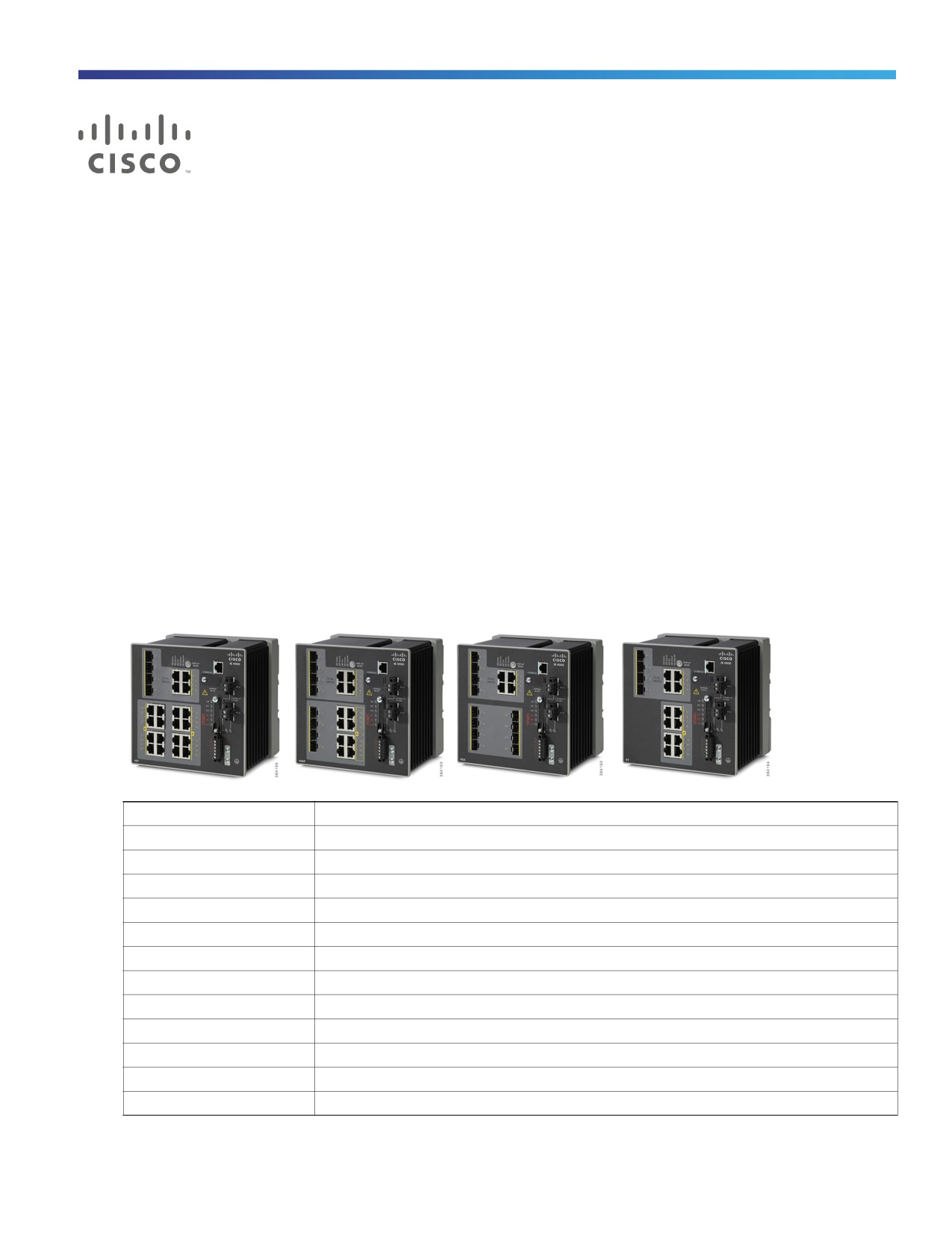
The Cisco® Industrial Ethernet (IE) 4000 Series is the latest addition to our ruggedized switching platforms and provides
superior high-bandwidth switching and proven Cisco IOS® Software-based routing capabilities for industrial
environments. The IE 4000 Series delivers highly secure access and industry-leading convergence using the Cisco
Resilient Ethernet Protocol (REP) and is built to withstand extreme environments while adhering to overall IT network
design, compliance, and performance requirements.
The IE 4000 Series is ideal for industrial Ethernet applications where hardened products are required, including factory
automation, energy and process control, intelligent transportation systems (ITS), oil and gas field sites, city surveillance
programs, and mining. With improved overall performance, greater bandwidth, a richer feature set, and enhanced
hardware, the Cisco IE 4000 Series complements the current industrial Ethernet portfolio of related Cisco industrial
switches.
The Cisco IE 4000 can easily be installed in your network. Through a user-friendly web device manager, the Cisco IE
4000 provides easy out-of-the-box configuration and simplified operational manageability to deliver advanced security,
data, video, and voice services over industrial networks.
Switch Models
Model
Description
IE-4000-4TC4G-E
4 FE Combo DL ports, 4 GE combo UL ports, w/FPGA
IE-4000-8T4G-E
8 FE Copper DL ports, 4 GE combo UL ports, w/FPGA
IE-4000-8S4G-E
8 FE Fiber DL ports, 4 GE combo UL ports, w/FPGA
IE-4000-4T4P4G-E
4 FE Copper DL ports + 4 FE Copper DL ports with POE1, 4 GE combo UL ports, w/FPGA
IE-4000-16T4G-E
16 FE Copper DL ports, 4 GE combo UL ports, w/FPGA
IE-4000-4S8P4G-E
4 FE Fiber DL ports + 8 FE Copper DL ports with POE1, 4 GE combo UL ports, w/FPGA
IE-4000-8GT4G-E
8 GE Copper DL ports, 4 GE combo UL ports, w/FPGA
IE-4000-8GS4G-E
8 GE Fiber DL ports, 4 GE combo UL ports, w/FPGA
IE-4000-4GC4GP4G-E
4 GE Combo DL ports + 4 GE Copper DL ports with POE1, 4 GE combo UL ports, w/FPGA
IE-4000-16GT4G-E
16 GE Copper DL ports, 4 GE combo UL ports, w/FPGA
IE-4000-8GT8GP4G-E
8 GE Copper DL ports + 8 GE Copper DL ports with POE1, 4 GE combo UL ports, w/FPGA
IE-4000-4GS8GP4G-E
4 GE Fiber DL ports + 8 GE Copper DL ports with POE1, 4 GE combo UL ports, w/FPGA
1
Product Overview
Front Panel Overview
1. IE-4000-8GT8GP4G-E supports up to 240W PoE, consisting of eight ports of PoE+ (30 W per port; IEEE 802.3at)
with temperature derating (131°F (55°C) at full 240W PoE power) and depending on the power source used.
All other PoE-capable models support up to 120W PoE, either PoE (15.4 W per port; IEEE 802.3af) or PoE+ (30
W per port; IEEE 802.3at) over the full operating temperature range.
Front Panel Overview
The illustrations in this section provide an overview of the variety of components available on the various switch models
in this product family. Not all models are illustrated.
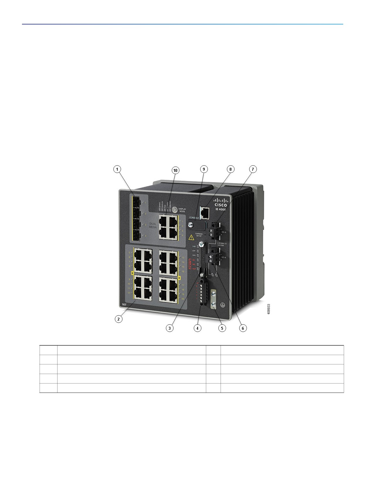
Figure 1
Cisco IE-4000-8GT8GP4G-E shown
1
SFP module slots (uplink ports)
6
Power connector DC-B
2
10/100/1000 Ethernet ports (downlink ports)
7
Power connector DC-A
3
Flash memory card slot
8
RJ-45 console port
4
Alarm connector
9
USB mini-Type B (console) port1
5
Protective ground connection
10
Dual-purpose ports (uplink ports)
1. Use a screwdriver to remove the port cover and access the port.
Ports and Slots
Note: Different configurations are available. Not all ports or slots are present in all configurations.
2
Product Overview
Ports and Slots
10/100/1000 BASE-T Downlink Ports
You can set the 10/100BASE-T downlink ports to operate at 10 or 100 Mb/s in full-duplex or half-duplex mode. You can
also set these ports for speed and duplex autonegotiation in compliance with IEEE 802.3AB. (The default setting is
autonegotiate.) When set for autonegotiation, the port senses the speed and duplex settings of the attached device and
advertises its own capabilities. If the connected device also supports autonegotiation, the switch port negotiates the best
connection (that is, the fastest line speed that both devices support, and full-duplex transmission if the attached device
supports it) and configures itself accordingly. In all cases, the attached device must be within 328 feet (100 meters).
100BASE-TX traffic requires Category 5 cable. 10BASE-T traffic can use Category 3 or Category 4 cables.
When connecting the switch to workstations, servers, routers, and Cisco IP phones, make sure that the cable is a
straight-through cable.
You can use the mdix auto interface configuration command in the command-line interface (CLI) to enable the automatic
medium-dependent interface crossover (auto-MDIX) feature. When the auto-MDIX feature is enabled, the switch detects
the required cable type for copper Ethernet connections and configures the interfaces accordingly. For configuration
information for this feature, see the switch software configuration guide or the switch command reference.
10/100/1000BASE-T Uplink Ports
The IEEE 802.3u 10/100/1000BASE-T uplink ports provide full-duplex 10, 100 or 1000 Mb/s connectivity over Category
5 unshielded twisted pair (UTP) copper cabling. The default setting is autonegotiate. The cable can be up to 100 m
(0.1 km) in length.
100/1000 Mb/s SFP Module Downlink Slots
The IEEE 802.3u 100 Mb/s SFP module downlink slots provide full-duplex 100 Mb/s connectivity over multi-mode (MM)
fiber cables or single-mode (SM) fiber cables. These ports use a SFP fiber-optic transceiver module that accepts a dual
LC connector. Check the SFP specifications for the cable type and length.
100/1000 Mb/s SFP Module Uplink Slots
The IEEE 802.3u 100 Mb/s SFP module uplink slots provide full-duplex 100 or 1000 Mb/s connectivity over multi-mode
(MM) fiber cables or single-mode (SM) fiber cables. These ports use a SFP fiber-optic transceiver module that accepts
a dual LC connector. Check the SFP specifications for the cable type and length.
Dual-Purpose Fast Ethernet Downlink Ports
You can configure the dual-purpose Fast Ethernet Downlink ports on the switch as either 10/100BASE-T ports or as 100
Mb/s SFP-module ports. You can set the 10/100 ports to autonegotiate, or you can configure them as fixed 10 or 100
Mb/s ports.
By default, the switch selects the medium for each dual-purpose port (10/100BASE-T or SFP). When a link is achieved
on one media type, the switch disables the other media type until the active link goes down. If links are active on both
media, the SFP-module port has priority, but you can use the media-type interface configuration command to manually
designate the port as an RJ-45 port or an SFP port.
You can configure the speed and duplex settings consistent with the selected media type. For information on configuring
interfaces, see the switch software configuration guide.
3

Product Overview
Ports and Slots
Dual-Purpose Gigabit Ethernet Uplink or Downlink Ports
You can configure the dual-purpose Gigabit Ethernet uplink or downlink ports on the switch as either 10/1001000BASE-T
ports or as 100/1000 Mb/s SFP-module ports. You can set the 10/100/1000BASE-T ports to autonegotiate, or you can
configure them as fixed 10, 100, or 1000 Mb/s (Gigabit) Ethernet ports.
By default, the switch selects the medium for each dual-purpose port (10/100/1000BASE-T or SFP). When a link is
achieved on one media type, the switch disables the other media type until the active link goes down. If links are active
on both media, the SFP-module port has priority, but you can use the media-type interface configuration command to
manually designate the port as an RJ-45 port or an SFP port.
You can configure the speed and duplex settings consistent with the selected media type. For information on configuring
interfaces, see the switch software configuration guide.
Management Ports
You can connect the switch to a PC running Microsoft Windows or to a terminal server through either the RJ-45 console
port or the USB mini-Type B console port, also referred to as the USB-mini console port. These ports use the following
connectors:
RJ-45 console port uses an RJ-45-to-DB-9 female cable.
USB-mini console port (5-pin connector) uses a USB Type A-to-5-pin mini-Type B cable.
The USB-mini console interface speeds are the same as the RJ-45 console interface speeds.
To use the USB-mini console port, you must install the Cisco Windows USB device driver on the device that is connected
to the USB-mini console port and that is running Microsoft Windows.
Note: For information about downloading the Cisco USB device driver, see Installing the Cisco Microsoft Windows XP,
2000, Vista, 7, 8, and 10 USB Device Driver, page 48.
With the Cisco Windows USB device driver, connecting and disconnecting the USB cable from the console port does not
affect Windows HyperTerminal operations. Mac OS X or Linux require no special drivers.
Note: The 5-pin mini-Type B connectors resemble the 4-pin mini-Type B connectors, but they are not compatible. Use
only the 5-pin mini-Type B. See Figure 2 on page 4.
Figure 2
USB Mini-Type B Port
The configurable inactivity timeout reactivates the RJ-45 console port if the USB-mini console port is activated, but no
input activity occurs for a specified time period. When the USB-mini console port deactivates due to a timeout, you can
restore its operation by disconnecting and reconnecting the USB cable. For information on using the CLI to configure the
USB-mini console interface, see the switch software guide.
4
Product Overview
Power Connectors
Power Connectors
DC Power Connector
You connect the DC power to the switch through the front panel connectors. The switch has a dual-feed DC power
supply; two connectors provide primary and secondary DC power (DC-A and DC-B). The DC power connectors are near
the top right of the front panel. See Figure 1 on page 2. Each power connector has an LED status indicator.
The switch power connectors are attached to the switch chassis. Each power connector has screw terminals for
terminating the DC power. All connectors are attached to the switch front panel with the provided captive screws.
The power connector labeling is on the panel. The positive DC power connection is labeled “+”, and the return
connection is labeled “-”.
The switch can operate with a single power source or with dual power sources. When both power sources are
operational, the switch draws power from the DC source with the higher voltage. If one of the two power sources fail,
the other continues to power the switch.
Alarm Connector
You connect the alarm signals to the switch through the alarm connector. The switch supports two alarm inputs and one
alarm output relay. The alarm connector is on the bottom right of the front panel. See Figure 3 on page 5.
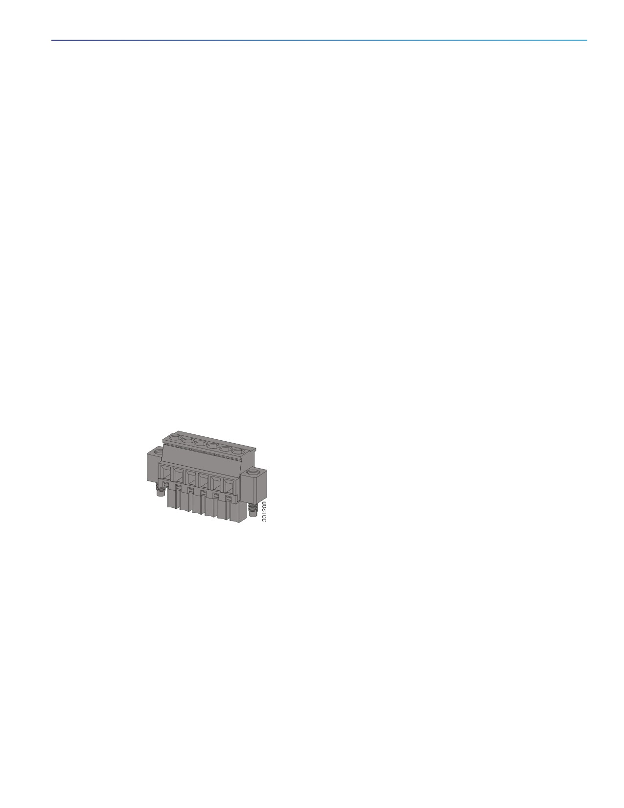
The alarm connector provides six alarm wire connections. The connector is attached to the switch front panel with the
provided captive screws.
Figure 3
Alarm Connector
Both alarm input circuits can sense if the alarm input is open or closed. The alarm inputs can be activated for
environmental, power supply, and port status alarm conditions. From the CLI, you can configure each alarm input as an
open or closed contact.
The alarm output circuit is a relay with a normally open and a normally closed contact. The switch is configured to detect
faults that are used to energize the relay coil and change the state on both of the relay contacts: normally open contacts
close, and normally closed contacts open. The alarm output relay can be used to control an external alarm device, such
as a bell or a light.
See the switch software configuration guide for instructions on configuring the alarm relays.
For more information about the alarm connector, see Cable and Connectors, page 59
5
Product Overview
Alarm Connector
SFP Modules Supported
The SFP modules are switch Ethernet SFP modules that provide connections to other devices. Depending on the switch
model, these field-replaceable transceiver modules provide uplink or downlink interfaces. The modules have LC
connectors for fiber-optic connections.
Refer to the IE4000 Data Sheet for details about the supported SFP Modules.
6
Product Overview
Alarm Connector
LEDs
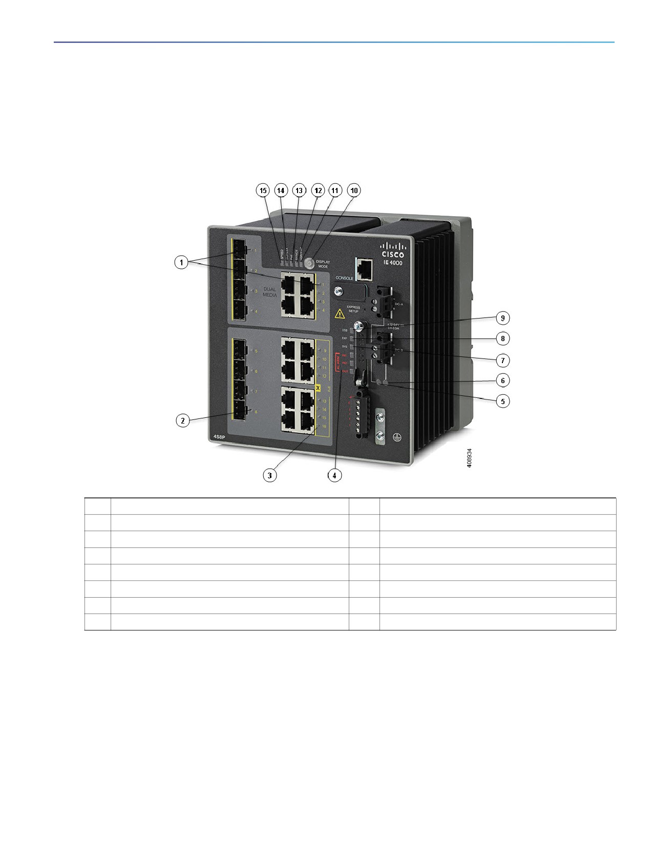
You can use the LEDs to monitor the switch status, activity, and performance. Figure 4 on page 7 and on page 10 show
the front panel LEDs.
Figure 4
LEDs on the Cisco IE 4000 Switch
1
Dual Media port LEDs
9
USB mini-Type B (console) port LED
2
SFP module slot LEDs
10
Display Mode Switch
3
10/100/1000 BASE-T downlink port LEDs
11
HSR/PRP
4
Alarm LEDs
12
SYNCE LED
5
Power connector DC-A LED
13
POE port status LED
6
Power connector DC-B LED
14
Duplex LED
7
System LED
15
Speed
8
Express Setup LED
Display Mode Switch
The Display Mode Switch allows you to choose the mode you want displayed by the port LEDs (items 7, 8, and 9 in
Figure 4 on page 7). The LEDs to the left of the switch indicate the chosen display mode. Each time you press the switch,
the mode indicator will move from Speed, Duplex, PoE, Synce, and HSR/PRP respectively.
7

Product Overview
Alarm Connector
Express Setup LED
The Express Setup LED displays the express setup mode for the initial configuration.
Color
Setup Status
Off (dark)
Switch is configured as a managed switch.
Solid green
Switch is operating normally.
Blinking green
Switch is in initial setup, in recovery, or initial setup is incomplete.
Solid red
Switch failed to start initial setup or recovery because there is no available switch port to
which to connect the management station. Disconnect a device from a switch port, and then
press the Express Setup button.
System LED
The System LED shows whether the system is receiving power and is functioning properly.
Color
System Status
Off
System is not powered on.
Blinking green
Boot fast is in progress.
Green
System is operating normally.
Red
Switch is not functioning properly.
USB-Mini Console LED
The USB-mini console LED shows which console port is in use. See Figure 4 on page 7 for the LED location. If you
connect a cable to a console port, the switch automatically uses that port for console communication. If you connect two
console cables, the USB-mini console port has priority.
Color
Description
Green
USB-mini console port is active.
RJ-45 console port LED is not active.
Off
Port is not active.
RJ-45 console port is active.
Alarm LEDs
Alarm OUT
Color
System Status
Off
Alarm OUT is not configured, or the switch is off.
Green
Alarm OUT is configured, no alarm detected.
Blinking red
Switch has detected a major alarm.
Red
Switch has detected a minor alarm.
8

Product Overview
Alarm Connector
Alarm IN1 and IN2
Color
System Status
Off
Alarm IN1 or IN2 not configured.
Green
Alarm IN1 or IN2 configured, no alarm detected.
Blinking red
Major alarm detected.
Red
Minor alarm detected.
Power Status LEDs
The switch can operate with one or two DC power sources. Each DC input has an associated LED that shows the status
of the corresponding DC input. If power is present on the circuit, the LED is green. If power is not present, the LED color
depends on the alarm configuration. If alarms are configured, the LED is red when power is not present; otherwise, the
LED is off.
If the switch has dual power sources, the switch draws power from the power source with the higher voltage. If one of
the DC sources fails, the alternate DC source powers the switch, and the corresponding power status LED is green. The
power status for the failed DC source is either off or red, depending on the alarm configuration.
Color
System Status
Green
Power is present on the associated circuit, system is operating normally.
Off
Power is not present on the circuit, or the system is not powered up.
Red
Power is not present on the associated circuit, and the power supply alarm is configured.
The Power A and Power B LEDs show that power is not present on the switch if the power input drops below the low
valid level. The power status LEDs only show that power is present if the voltage at the switch input exceeds the valid
level.
For information about the power LED colors during the boot fast sequence, see Verifying Switch Operation, page 39.
Port Status LEDs
Each port and SFP uplink slot has a status LED, as shown in Figure 4 on page 7 and described below.
Color
System Status
Off
No link.
Solid green
Link present.
Blinking green
Activity. Port is sending or receiving data.
Alternating
Link fault. Error frames can affect connectivity, and errors such as excessive collisions, CRC
green-amber
errors, and alignment and jabber errors are monitored for a link-fault indication.
Solid amber
Port is not forwarding. The port was disabled by management, an address violation, or STP.
After a port is reconfigured, the port LED can remain amber for up to 30 seconds while STP
checks the switch for possible loops.
9

Product Overview
Flash Memory Card
Dual-Purpose Port LEDs
The Dual Purpose LEDs show how the port is being used (Ethernet or SFP module). The LED colors have the same
meanings as for the Port Status LEDs, page 9.
PoE Status LED
The PoE STATUS LEDs are located on the front panel, next to the PoE ports (models equipped with PoE ports).The LEDs
display the functionality and status of the adjacent PoE ports.
Color
PoE Status
Off
PoE is off. If the powered device is receiving power from a non-PoE power
source, the port LED is off even if the powered device is connected to the switch
port.
Green
PoE is on. The port LED is green only when the PoE port is providing power.
Alternating green
PoE is denied because providing power to the powered device will exceed the
and amber
switch power capacity.
Flashing amber
PoE is off due to a fault.
Caution: Noncompliant cabling or powered devices can cause a PoE port
fault. Use only standard-compliant cabling to connect Cisco pre-standard
IP Phones and wireless access points or IEEE 802.3af-compliant devices.
You must remove any cable or device that causes a PoE fault.
Amber
PoE for the port is disabled. (PoE is enabled by default.)
Flash Memory Card
The switch supports a flash memory card that makes it possible to replace a failed switch without reconfiguring the new
switch. The slot for the flash memory card is on the front of the switch. The flash card is hot swappable and can be
accessed on the front panel in non hazardous locations only. A cover protects the flash card and holds the card firmly in
place. The cover is hinged and closed with a captive screw. This prevents the card from coming loose and protects
against shock and vibration.
Note: For more information on inserting and removing the flash memory card, see Installing or Removing the Flash
Memory Card (Optional), page 16.
Note: The replacement SD card part number is SD-IE-1GB.
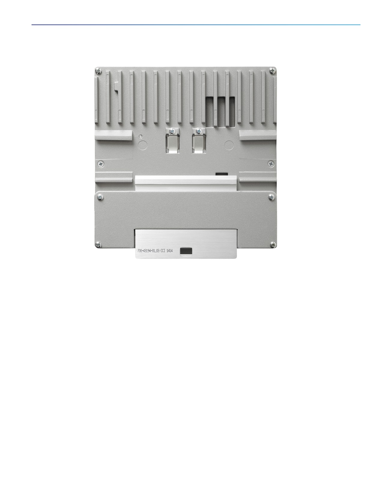
Rear Panel
The rear panel of the switch has a latch for installation on a DIN rail. See Figure 5 on page 11. The latch is spring-loaded
to move down to position the switch over a DIN rail and return to the original position to secure the switch to a DIN rail.
10
Product Overview
Management Options
Figure 5
Cisco IE 4000 Switch Rear Panel
Management Options
The switch supports these management options:
Cisco Network Assistant
Cisco Network Assistant is a PC-based network management GUI application optimized for LANs of small- and
medium-sized businesses. Using the GUI, you can configure and manage switch clusters or standalone switches.
Cisco Network Assistant is available at no cost and can be downloaded from this URL:
For information on starting the Cisco Network Assistant application, see the Getting Started with Cisco Network
Assistant guide on Cisco.com.
Device Manager
You can use Device Manager, which is in the switch memory, to manage individual and standalone switches. This
web interface offers quick configuration and monitoring. You can access Device Manager from anywhere in your
network through a web browser. For more information, see the Device Manager online help.
Cisco IOS CLI
11
Product Overview
Network Configurations
The switch CLI is based on Cisco IOS software and is enhanced to support desktop-switching features. You can fully
configure and monitor the switch. You can access the CLI either by connecting your management station directly to
the switch management port, or a console port, or by using Telnet from a remote management station. See the
switch command reference on Cisco.com for more information.
SNMP network management
You can manage switches from a SNMP-compatible management station that is running platforms such as HP
OpenView or SunNet Manager. The switch supports a comprehensive set of Management Information Base (MIB)
extensions and four Remote Monitoring (RMON) groups. See the switch software configuration guide on Cisco.com
and the documentation that came with your SNMP application for more information.
Common Industrial Protocol
The Common Industrial Protocol (CIP) management objects are supported. The Cisco IE 4000 can be managed by
CIP-based management tools, allowing the user to manage an entire industrial automation system with one tool.
PROFINET TCP/IP and RT
This switch supports PROFINET TCP/IP and RT and can be managed by Siemens' automation software such as STEP
7.
Network Configurations
See the switch software configuration guide on Cisco.com for network configuration concepts and examples of using
the switch to create dedicated network segments and interconnecting the segments through Gigabit Ethernet
connections.
12
Switch Installation
This chapter describes how to install your switch, verify the boot fast, and connect the switch to other devices. It also
includes information specifically for installations in hazardous environments.
Read these topics, and perform the procedures in this order:
Preparing for Installation, page 13
Installing or Removing the Flash Memory Card (Optional), page 16
Connecting to a Console Port (Optional), page 17
Connecting to Power, page 18
Installing the Switch, page 29
Connecting Alarm Circuits, page 31
Connecting Destination Ports, page 35
Verifying Switch Operation, page 39
Where to Go Next, page 39
Preparing for Installation
This section provides information about these topics:
Warnings, page 13
Installation Guidelines, page 15
Verifying Package Contents, page 16
Warnings
These warnings are translated into several languages in the Regulatory Compliance and Safety Information for this
switch.
Warning: Before working on equipment that is connected to power lines, remove jewelry (including rings,
necklaces, and watches). Metal objects will heat up when connected to power and ground and can cause serious
burns or weld the metal object to the terminals. Statement 43
Warning: Exposure to some chemicals could degrade the sealing properties of materials used in the sealed relay
device. Statement 381
Warning: Do not work on the system or connect or disconnect cables during periods of lightning activity. Statement
1001
Warning: Before performing any of the following procedures, ensure that power is removed from the DC circuit.
Statement 1003
13
Switch Installation
Preparing for Installation
Warning: Read the installation instructions before you connect the system to its power source. Statement 1004
Warning: This unit is intended for installation in restricted access areas. A restricted access area can be accessed
only through the use of a special tool, lock and key, or other means of security. Statement 1017
Warning: This equipment must be grounded. Never defeat the ground conductor or operate the equipment in the
absence of a suitably installed ground conductor. Contact the appropriate electrical inspection authority or an
electrician if you are uncertain that suitable grounding is available. Statement 1024
Warning: This unit might have more than one power supply connection. All connections must be removed to
de-energize the unit. Statement 1028
Warning: Only trained and qualified personnel should be allowed to install, replace, or service this equipment.
Statement 1030
Warning: Ultimate disposal of this product should be handled according to all national laws and regulations.
Statement 1040
Warning: For connections outside the building where the equipment is installed, the following ports must be
connected through an approved network termination unit with integral circuit protection.
10/100/1000 Ethernet Statement 1044
Warning: To prevent the system from overheating, do not operate it in an area that exceeds the maximum
recommended ambient temperature of:
158 F (70 C). For IE-4000-8GT8GP4G maximum recommend ambient is 131 F (55 C) at max POE budget of 240W.
Statement 1047
Warning: In switch installations in a hazardous location, the DC power source could be located away from the
vicinity of the switch. Before performing any of the following procedures, locate the DC circuit to ensure that the
power is removed and cannot be turned on accidentally, or verify that the area is nonhazardous before proceeding.
Statement 1059
Warning: This equipment is supplied as “open type” equipment. It must be mounted within an enclosure that is
suitably designed for those specific environmental conditions that will be present and appropriately designed to
prevent personal injury resulting from accessibility to live parts. The interior of the enclosure must be accessible
only by the use of a tool.
The enclosure must meet IP 54 or NEMA type 4 minimum enclosure rating standards. Statement 1063
Warning: When used in a Class I, Division 2, hazardous location, this equipment must be mounted in a suitable
enclosure with proper wiring method, for all power, input and output wiring, that complies with the governing
electrical codes and in accordance with the authority having jurisdiction over Class I, Division 2 installations.
Statement 1066
Warning: Installation of the equipment must comply with local and national electrical codes. Statement 1074
Warning: Explosion Hazard—The area must be known to be nonhazardous before installing, servicing, or replacing
the unit. Statement 1082
Warning: Explosion Hazard—Substitution of components may impair suitability for Class I, Division 2/Zone 2.
Statement 1083
Caution: When installed in a Class I, Div/Zone 2 hazardous location environment, this equipment must be installed
in a min. IP54, ATEX certified enclosure.
Caution: Airflow around the switch must be unrestricted. To prevent the switch from overheating, there must be the
following minimum clearances:
- Top and bottom: 2.0 in. (50.8 mm)
- Sides: 2.0 in. (50.8 mm)
- Front: 2.0 in. (50.8 mm)
Contact your Cisco Technical Assistance Centre (TAC) if tighter spacings are required.
14
Switch Installation
Preparing for Installation
Caution: When installed in a Class I, Div/Zone 2 hazardous location environment, this equipment must be installed
in a pollution degree 2 environment per IEC 60664-1)
Caution: This equipment is suitable for use in Class I, Division 2, Groups A, B, C, D, or only nonhazardous locations.
Caution: Airflow around the switch must be unrestricted. To prevent the switch from overheating, there must be the
following minimum clearances:
- Top and bottom: 2.0 in. (50.8 mm)
- Sides: 2.0 in. (50.8 mm)
- Front: 2.0 in. (50.8 mm)
Installation Guidelines
When determining where to place the switch, observe these guidelines.
Environment and Enclosure Guidelines
Review these environmental and enclosure guidelines before installation:
This equipment is intended for use in a Pollution Degree 2 industrial environment, in overvoltage Category II
applications (as defined in IEC publication 60664-1), at altitudes up to 9842 ft (3 km) without derating.
This equipment is considered Group 1, Class A industrial equipment, according to IEC/CISPR Publication 11. Without
appropriate precautions, there may be potential difficulties ensuring electromagnetic compatibility in other
environments due to conducted as well as radiated disturbance.
This equipment is supplied as open-type equipment. It must be mounted within an enclosure that is suitably
designed for those specific environmental conditions that will be present and appropriately designed to prevent
personal injury resulting from accessibility to live parts. The enclosure must have suitable flame-retardant properties
to prevent or minimize the spread of flame, complying with a flame-spread rating of 5VA, V2, V1, V0 (or equivalent)
if nonmetallic. The interior of the enclosure must be accessible only by the use of a tool. Subsequent sections of this
publication might contain additional information regarding specific enclosure-type ratings that are required to
comply with certain product safety certifications.
General Guidelines
Before installation, observe these general guidelines:
Caution: Proper ESD protection is required whenever you handle Cisco equipment. Installation and maintenance
personnel should be properly grounded by using ground straps to eliminate the risk of ESD damage to the switch.
Do not touch connectors or pins on component boards. Do not touch circuit components inside the switch. When
not in use, store the equipment in appropriate static-safe packaging.
The switch only meets the requirements of IEC 61850-3 when powered by a redundant power supply configuration.
If you are responsible for the application of safety-related programmable electronic systems (PES), you need to be
aware of the safety requirements in the application of the system and be trained in using the system.
Caution: The device is designed to mount on a DIN rail that conforms to Standard EN50022.
When determining where to place the switch, observe these guidelines:
Before installing the switch, first verify that the switch is operational by powering it on and observing boot fast. Follow
the procedures in the Verifying Switch Operation, page 39.
For 10/100 ports and 10/100/1000 ports, the cable length from a switch to an attached device cannot exceed 328
feet (100 meters).
15
Switch Installation
Installing or Removing the Flash Memory Card (Optional)
For 100BASE-FX fiber-optic ports, the cable length from a switch to an attached device cannot exceed 6562 ft (2
km).
Clearance to front and rear panels meets these conditions:
— Front-panel LEDs can be easily read.
— Access to ports is sufficient for unrestricted cabling.
— Front-panel direct current (DC) power connectors and the alarm connector are within reach of the connection
to the DC power source.
Airflow around the switch must be unrestricted. To prevent the switch from overheating, you must have the following
minimum clearances:
— Top and bottom: 2.0 in. (50.8 mm)
— Sides: 2.0 in. (50.8 mm)
— Front: 2.0 in. (50.8 mm)
Caution: When the switch is installed in an industrial enclosure, the temperature within the enclosure is greater than
normal room temperature outside the enclosure.
Ensure temperatures inside the enclosure conform to device specifications detailed in Table 5 on page 67.
Cabling is away from sources of electrical noise, such as radios, power lines, and fluorescent lighting fixtures.
Verifying Package Contents
If any item is missing or damaged, contact your Cisco representative or reseller for support.
Installing or Removing the Flash Memory Card (Optional)
The software/firmware is stored on the SD card memory from factory default. Optionally, you can execute the sync
command to copy the software/firmware (including directory) to on-board memory (flash memory), then remove the SD
card. it is strongly recommended that you use the SD card to boot or store the config for future easy replacement, in
case of a hardware failure.
Warning: Do not insert or remove the flash card while power is on; an electrical arc can occur. This could cause an
explosion in hazardous location installations. Be sure that power is removed or the area is nonhazardous before
proceeding. Statement 379
To install or replace the flash memory card, follow these steps:
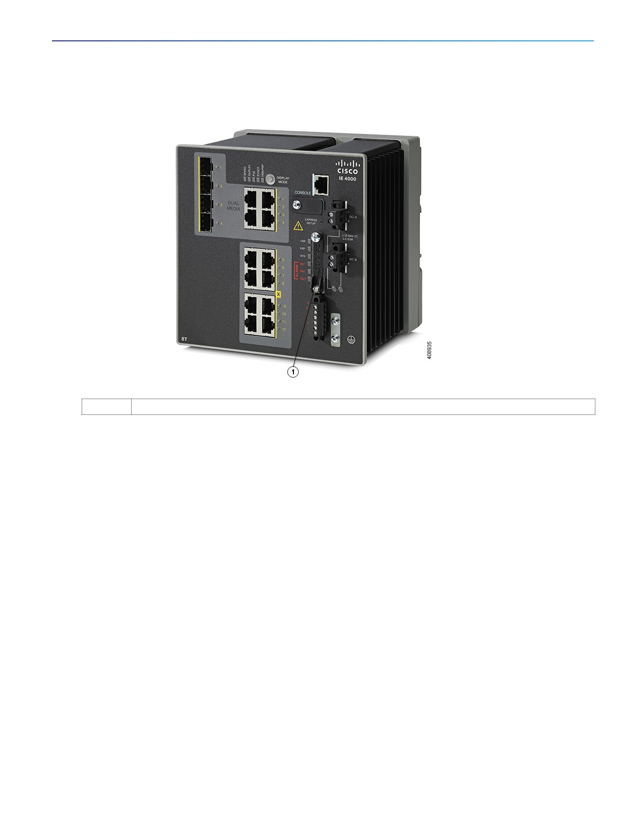
1. On the front of the switch, locate the door that protects the flash memory card slot. Loosen the captive screw at the
top of the door using a Phillips screwdriver to open the door. See Figure 6 on page 17.
16
Switch Installation
Connecting to a Console Port (Optional)
Figure 6
Installing the Flash Memory Card in the Switch
1
Flash Memory Card Slot
2. Install or remove the card:
To install a card, slide it into the slot, and press it in until it clicks in place. The card is keyed so that you cannot insert
it the wrong way.
To remove the card, push it in until it releases for it to pop out. Place it in an antistatic bag to protect it from static
discharge.
3. After the card is installed, close the guard door and fasten the captive screw using a Phillips screwdriver to keep the
door in place.
Connecting to a Console Port (Optional)
You can also enter CLI commands through the console port. For more information about this process see Accessing the
CLI Through the Console Port, page 45.
Warning: If you connect or disconnect the console cable with power applied to the switch or any device on the
network, an electrical arc can occur. This could cause an explosion in hazardous location installations. Be sure that
power is removed or the area is nonhazardous before proceeding.
Statement 1080
17
Switch Installation
Connecting to Power
Connecting to Power
Tools and Equipment
Obtain these necessary tools and equipment:
Ratcheting torque flathead screwdriver that exerts up to 18 in-lb (2.03 N-m) of pressure.
For the protective ground connector, obtain a single or pair of stu size 6 ring terminals (such as Hollingsworth part
number R3456B or equivalent).
Crimping tool (such as Thomas & Bett part number WT4000, ERG-2001, or equivalent).
10-gauge copper ground wire.
For DC power connections, use UL- and CSA-rated, style 1007 or 1569 twisted-pair copper appliance wiring
material (AWM) wire.
Wire-stripping tools for stripping 10- and 18-gauge wires.
A number-2 Phillips screwdriver.
A flat-blade screwdriver.
Supported Power Supplies
The supported power supplies are listed in Table 1 on page 19.
18

Switch Installation
Connecting to Power
Table 1
Supported Power Supplies
PWR-IE65W-
PWR-IE65W-
PWR-IE170W-
PWR-IE170W-
PWR-IE50W-
PWR-IE50W-
PC-DC
PC-AC
PC-DC
PC-AC
AC-IEC
AC
Current
DC-DC
AC-DC
DC-DC
AC-DC
AC-DC
AC-DC
Input
18-60
110/220 VAC
10.8-60
110/220 VAC
110/220 VAC
110/220VAC
VDC/4.3 Amp
and 88-300
VDC/23 Amp
and 88-300
and 88-300
VDC
VDC/2.1 Amp
VDC
Output
54VDC/1.2
54VDC/1.2
54VDC/3.15
54VDC/3.15
24VDC/2.1Am
24 VDC /
Amp
Amp
Amp
Amp
p
2.1Amp
Dimensions
5.9 in H x
5.9 in. H x
5.93 in (149.8
5.93 in. (150.6
5.8 in. H x
5.8 in. H x
2.1 in. W x
2.1 in. W x
mm) H x 4.47
mm) H x
2 in. W x
2 in. W x
4.9 in. D
4.9 in. D
in. (113.5 mm)
3.72 in. (94.5
4.4 in. D
4.4 in. D
W x
mm) W x
5.7 in. (144.7
5.6 in. (142.2
mm) D
mm) D
Usage
Designed for
Designed for
Designed for
Designed for
No POE
No POE
up to 25W of
up to 25W of
up to 8 POE
up to 8 POE
support
support
POE load
POE load
ports or 123W
ports or 123W
of POE power.
of POE power.
Installing the Power Converter on a DIN Rail, Wall, or Rack Adapter
You install the power converter on a DIN rail, wall, or rack as you would a switch module.
Warning: This equipment is supplied as “open type” equipment. It must be mounted within an enclosure that is
suitably designed for those specific environmental conditions that will be present and appropriately designed to
prevent personal injury resulting from accessibility to live parts. The interior of the enclosure must be accessible
only by the use of a tool.
The enclosure must meet IP 54 or NEMA type 4 minimum enclosure rating standards. Statement 1063
Caution: To prevent the switch assemble from overheating, there must be sufficient spacings as explained under
Installation Guidelines, page 15, between any other switch assembly.
Grounding the Switch
Make sure to follow any grounding requirements at your site.
Warning: This equipment must be grounded. Never defeat the ground conductor or operate the equipment in the
absence of a suitably installed ground conductor. Contact the appropriate electrical inspection authority or an
electrician if you are uncertain that suitable grounding is available. Statement 1024
Warning: This equipment is intended to be grounded to comply with emission and immunity requirements. Ensure
that the switch functional ground lug is connected to earth ground during normal use. Statement 1064
Caution: To make sure that the equipment is reliably connected to earth ground, follow the grounding procedure
instructions, and use a UL-listed ring terminal lug suitable for number 10-to-12 AWG wire, such as Hollingsworth
part number R3456B or equivalent)
Caution: Use at least a 4 mm2 conductor to connect to the external grounding screw.
The ground lug is not supplied with the switch. You can use one of the these options:
19
Switch Installation
Connecting to Power
Single ring terminal
Two single ring terminals
To ground the switch to earth ground by using the ground screw, follow these steps:
1. Use a standard Phillips screwdriver or a ratcheting torque screwdriver with a Phillips head to remove the ground
screw from the front panel of the switch. Store the ground screw for later use.
2. Use the manufacturer’s guidelines to determine the wire length to be stripped.
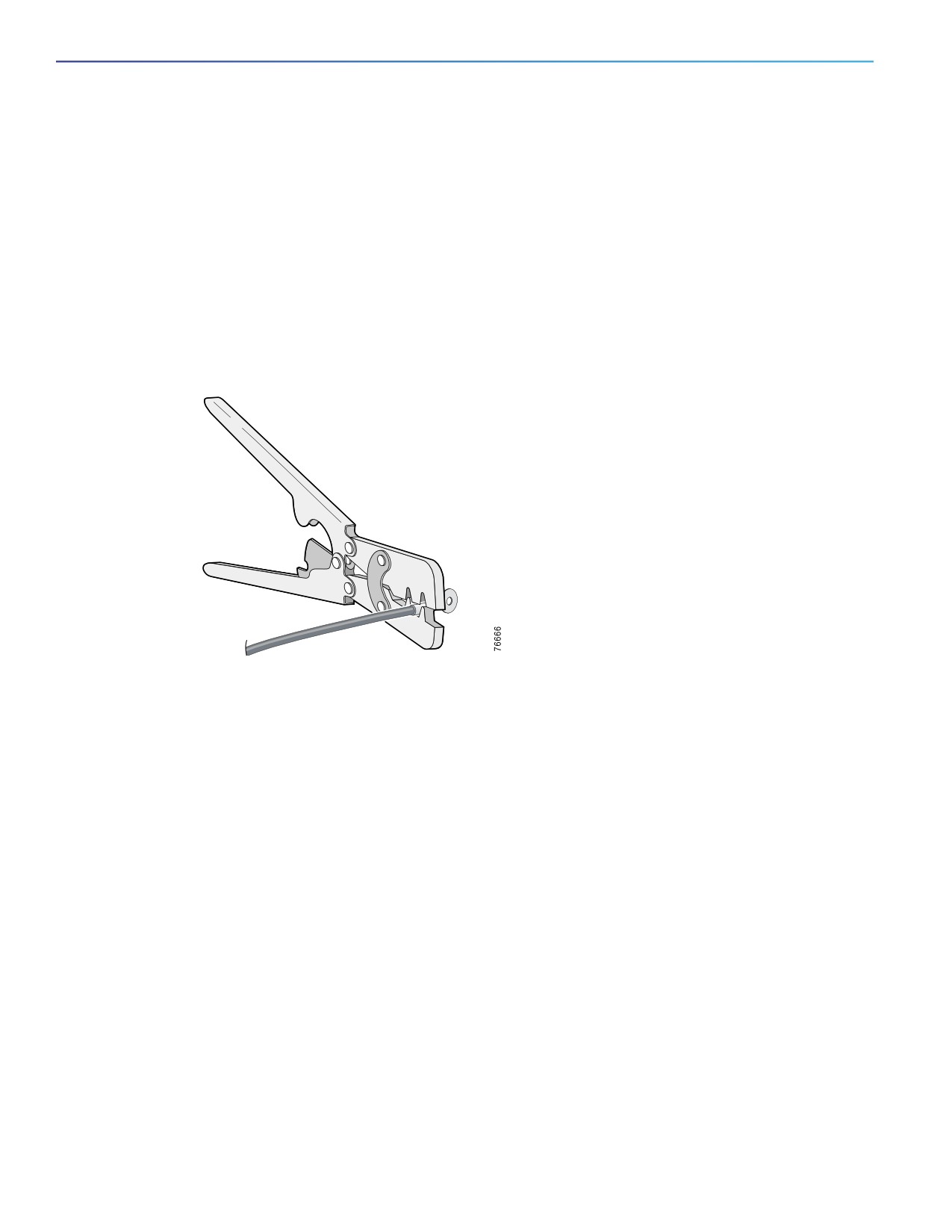
3. Insert the ground wire into the ring terminal lug, and using a crimping tool, crimp the terminal to the wire. See
Figure 7 on page 20. If two ring terminals are being used, repeat this action for a second ring terminal.
Figure 7
Crimping the Ring Terminal
4. Slide the ground screw through the terminal.
5. Insert the ground screw into the functional ground screw opening on the front panel.
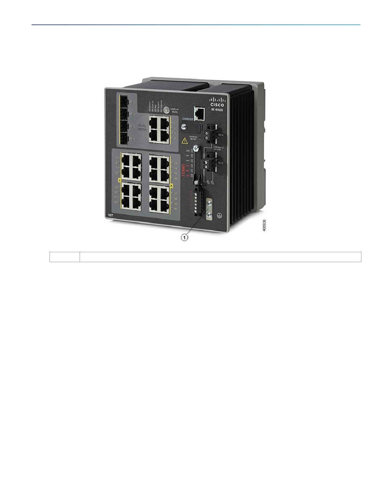
6. Use a ratcheting torque screwdriver to tighten the ground screws and ring terminal to the switch front panel. The
torque should not exceed 4.5 in-lb (0.51 N-m). See Figure 8 on page 21.
20
Switch Installation
Connecting to Power
Figure 8
Ground-Lug Screw
1
Ground-Lug Screw
7. Attach the other end of the ground wire to a grounded bare metal surface, such as a ground bus, a grounded DIN
rail, or a grounded bare rack.
Connecting the Power Converter to an AC Power Source
These sections describe the steps required to connect the power converter to an AC power source:
Preparing the AC Power Connection, page 21
Connecting the AC Power Source to the Power Converter, page 22
Preparing the AC Power Connection
To connect the power converter to an AC power source, you need an AC power cord. Power cord connector types and
standards vary by country. Power-cord wiring color codes also vary by country. You must to have a qualified electrician
select, prepare, and install the appropriate power cord to the power supply.
Note: Use copper conductors only, rated at a minimum temperature of 167°F (75°C).
Note: This section does not apply to PWR-IE50W-AC-IEC, which has pluggable IEC connector.
21
Switch Installation
Connecting to Power
Connecting the AC Power Source to the Power Converter
Caution: AC power sources must be dedicated AC branch circuits. Each branch circuit must be protected by a
dedicated two-pole circuit breaker.
Caution: Do not turn on AC power until the wiring is secured.
1. Remove the plastic cover from the input power terminals and set it aside.
2. Insert the exposed ground wire lead (10-to-12 AWG cable) into the power converter ground wire connection. Ensure
that only wire with insulation extends from the connector. Note that the position of the power converter may vary on
different switch models.
3. Tighten the ground wire terminal block screw.
Note: Torque to 10 in-lb (1.13Nm).
4. Insert the line and neutral wire leads into the terminal block line and neutral connections. Make sure that you cannot
see any wire lead. Ensure that only wire with insulation extends from the connectors.
5. Tighten the line and neutral terminal block screws.
Note: Torque to 10 in-lb (1.13Nm).
6. Replace the plastic cover over the terminal block.
7. Connect the other end of the wiring to your AC power source.
Connecting the Power Converter to a DC Power Source
You can also connect the power converter to a DC power source. Several power supplies can be used. Refer to Table 1
on page 19 for the appropriate DC input ratings.
Note: Use copper conductors only, rated at a minimum temperature of 167°F (75°C).
1. Measure a single length of stranded copper wire long enough to connect the power converter to the earth ground.
The wire color might differ depending on the country that you are using it in.
For connections from the power converter to earth ground, use shielded 14-AWG stranded copper wire.
2. Measure a length of twisted-pair copper wire long enough to connect the power converter to the DC power source.
For DC connections from the power converter to the DC source, use 10-AWG twisted-pair copper wire.
3. Using a 18-gauge wire-stripping tool, strip the ground wire and both ends of the twisted pair wires to 0.25 inch (6.3
mm) ± 0.02 inch (0.5 mm). Do not strip more than 0.27 inch (6.8 mm) of insulation from the wires. Stripping more
than the recommended amount of wire can leave exposed wire from the power and relay connector after installation.
4. Connect one end of the stranded copper wire to a grounded bare metal surface, such as a ground bus, a grounded
DIN rail, or a grounded bare rack.
5. Insert the other end of the exposed ground wire lead into the earth-ground wire connection on the power converter
terminal block. Note that the position of the power converter may vary on different switch models.
6. Tighten the earth-ground wire connection terminal block screw.
Note: Torque to 8 in.-lb, not to exceed 10 in-lb.
22
Switch Installation
Connecting to Power
Warning: An exposed wire lead from a DC-input power source can conduct harmful levels of electricity. Be sure that
no exposed portion of the DC-input power source wire extends from the power and relay connector. Statement 122
7. Insert the twisted-pair wire leads into the terminal block line and neutral connections. Insert the wire (labeled number
1 in Figure 8 on page 21) lead into the neutral wire connection and the wire (labeled number 2 in Figure 8 on
page 21) lead into the line wire connection. Ensure that only wire with insulation extends from the connectors. See
Figure 8 on page 21.
8. Tighten the line and neutral terminal block screws.
Note: Torque to 8 in.-lb, not to exceed 10 in-lb.
9. Connect the red wire to the positive pole of the DC power source, and connect the black wire to the return pole.
Ensure that each pole has a current-limiting-type fuse rated to 30 Amp.
Wiring the DC Power Source
Read these cautions and warnings before wiring the switch the DC power source.
Warning: A readily accessible two-poled disconnect device must be incorporated in the fixed wiring.
Statement 1022
Warning: This product relies on the building’s installation for short-circuit (overcurrent) protection. Ensure that the
protective device is rated not greater than: 7.5A.
Statement 1005
Warning: Installation of the equipment must comply with local and national electrical codes. Statement 1074
Warning: Before performing any of the following procedures, ensure that power is removed from the DC circuit.
Statement 1003
Warning: Only trained and qualified personnel should be allowed to install, replace, or service this equipment.
Statement 1030
Caution: For wire connections to the power and alarm connectors, you must use UL- and CSA-rated, style 1007 or
1569 twisted-pair copper appliance wiring material (AWM) wire (such as Belden part number 9318).
Caution: On switches that support PoE, do not connect the negative (return) terminal of the DC power source to
earth ground
To wire the switch to a DC power source, follow these steps:
1. Locate the two power connectors on the switch front panel labeled DC-A and DC-B.
2. Identify the connector positive and return DC power connections. The labels for power connectors DC-A and DC-B
are on the switch panel as displayed below.
Label
Connection
+
Positive DC power connection
–
Return DC power connection
3. Measure two strands of twisted-pair copper wire (16-to-18 AWG) long enough to connect to the DC power source.
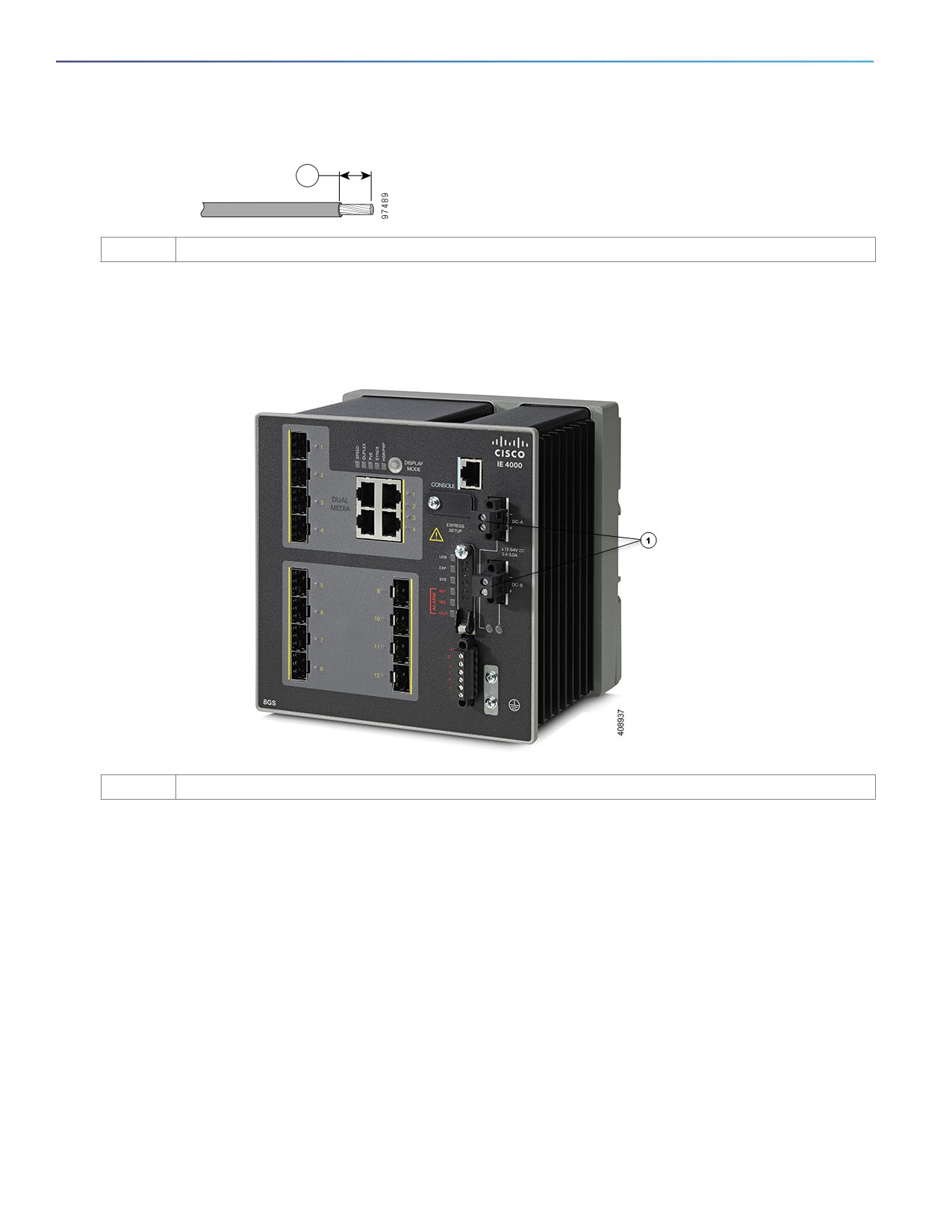
4. Using an 18-gauge wire-stripping tool, strip each of the two twisted pair wires coming from each DC-input power
source to 0.25 inch (6.3 mm) ± 0.02 inch (0.5 mm). Do not strip more than 0.27 inch (6.8 mm) of insulation from the
wire. Stripping more than the recommended amount of wire can leave exposed wire from the power connector after
installation.
23
Switch Installation
Connecting to Power
Figure 9
Stripping the Power Connection Wire
1
1
0.25 in. (6.3 mm) ± 0.02 in. (0.5 mm)
5. Remove the two captive screws that attach the power connector to the switch, and remove the power connector.
Remove both connectors if you are connecting to two power sources. See Figure 10 on page 24.
Figure 10
Removing the Power Connectors from the Switch
1
Power Connectors
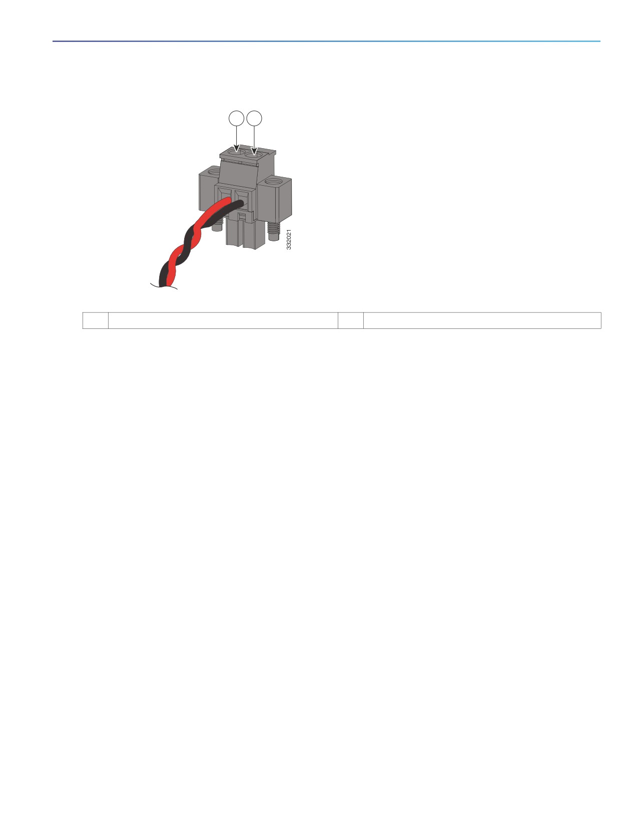
6. On the power connector, insert the exposed part of the positive wire into the connection labeled “+” and the exposed
part of the return wire into the connection labeled “-”. See Figure 11 on page 25. Make sure that you cannot see any
wire lead. Only wire with insulation should extend from the connector.
Warning: An exposed wire lead from a DC-input power source can conduct harmful levels of electricity. Be sure that
no exposed portion of the DC-input power source wire extends from the connector(s) or terminal block(s).
Statement 122
24
Switch Installation
Connecting to Power
Figure 11
Inserting Wires in the Power Connector
1
2
1
Power source positive connection
2
Power source return connection
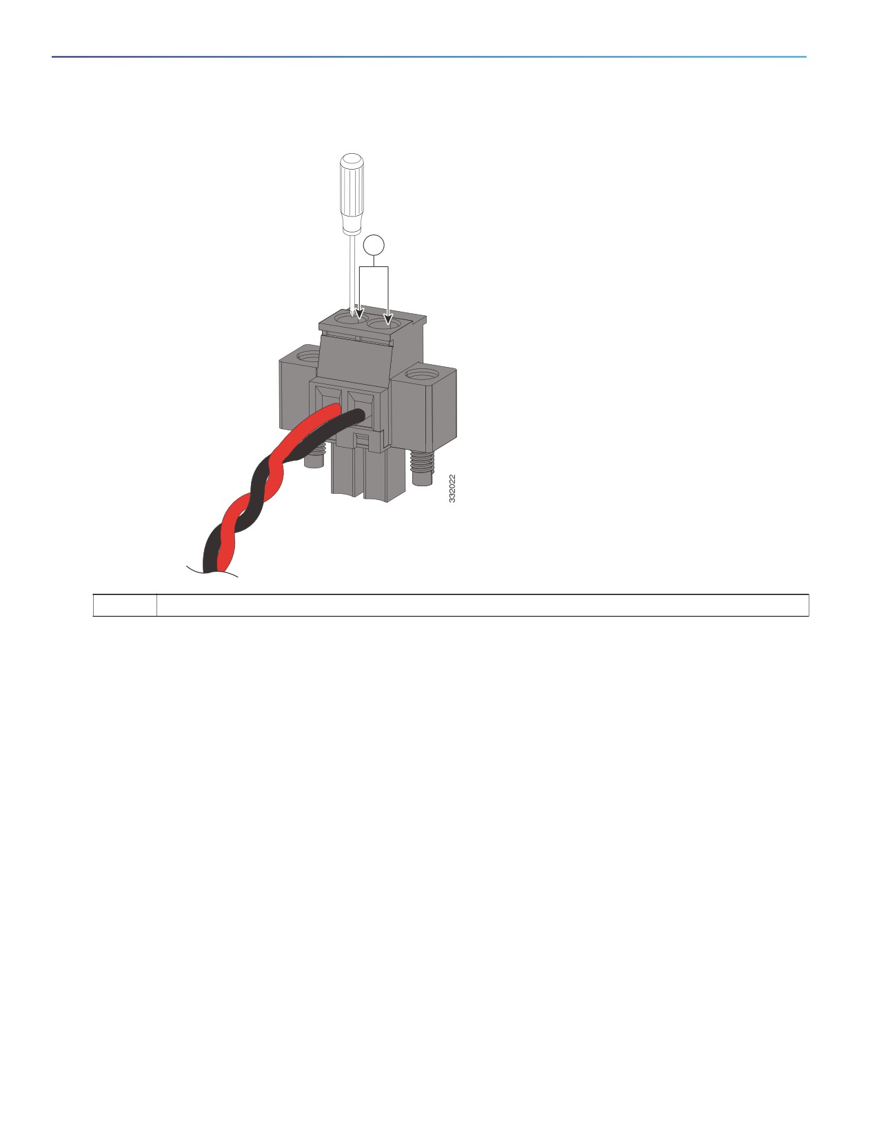
7. Use a ratcheting torque flathead screwdriver to torque the power connector captive screws (above the installed wire
leads) to 5in-lb (0.565 Nm). See Figure 12 on page 26.
Caution: Do not over-torque the power connector’s captive screws. The torque should not exceed 5in-lb (0.565
Nm).
25
Switch Installation
Connecting to Power
Figure 12
Torquing the Power Connector Captive Screws
1
1
Power connector captive screws
8. Connect the other end of the positive wire to the positive terminal on the DC power source, and connect the other
end of the return wire to the return terminal on the DC power source.
When you are testing the switch, one power connection is sufficient. If you are installing the switch and are using a
second power source, repeat Step 4 through Step 8 using the second power connector.
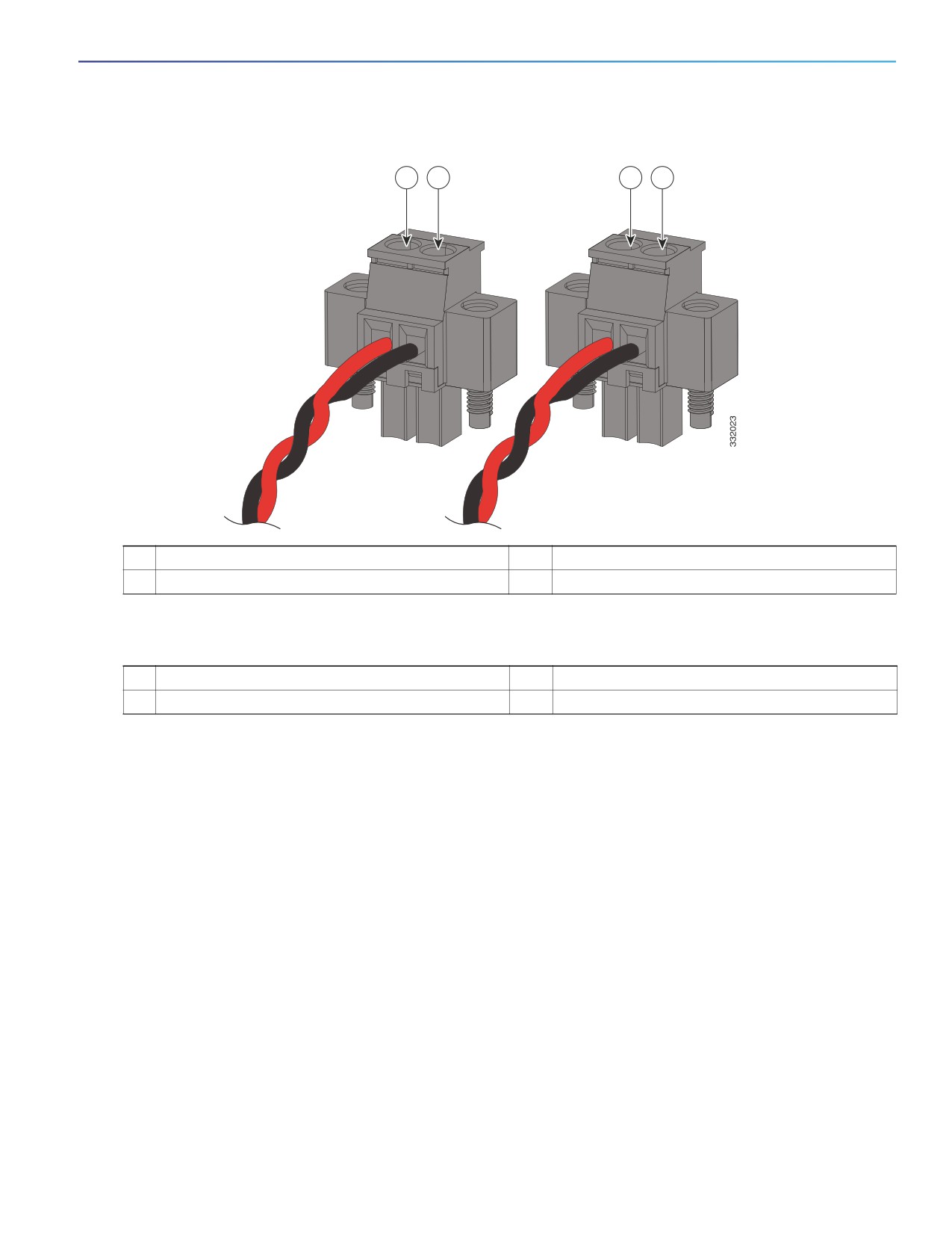
Figure 13 on page 27 shows the completed DC-input wiring on a power connector for a primary power source and an
optional secondary power source.
26
Switch Installation
Connecting to Power
Figure 13
Completed DC Power Connections on the Power Connectors
1
2
3
4
1
Power source A positive connection
3
Power source B positive connection
2
Power source A return connection
4
Power source B return connection
If your power source is -48 VDC, this table describes the your wiring connections for Figure 13 on page 27.
1
Power source A ground connection
3
Power source B ground connection
2
Power source A -48 VDC connection
4
Power source B -48 VDC connection
Attaching the Power Connectors to the Switch
To attach the power connectors to the front panel of the switch, follow these steps:
1. Insert one power connector into the DC-A receptacle on the switch front panel, and the other into the DC-B
receptacle. See Figure 10 on page 24.
Warning: Failure to securely tighten the captive screws can result in an electrical arc if the connector is accidentally
removed. Statement 397
Warning: This product relies on the building’s installation for short-circuit (overcurrent) protection. Ensure that the
protective device is rated not greater than: 7.5A. Statement 1005
Warning: When you connect or disconnect the power and/or alarm connector with power applied, an electrical arc
can occur. This could cause an explosion in hazardous area installations. Be sure that all power is removed from the
switch and any other circuits. Be sure that power cannot be accidentally turned on or verify that the area is
nonhazardous before proceeding. Statement 1058
Warning: Use twisted-pair supply wires suitable for 86°F (30°C) above surrounding ambient temperature outside
the enclosure. Statement 1067
27
Switch Installation
Connecting to Power
Warning: Installation of the equipment must comply with local and national electrical codes. Statement 1074
2. Use a ratcheting torque flathead screwdriver to tighten the captive screws on the sides of the power connectors.
When you are testing the switch, one power source is sufficient. If you are installing the switch and are using a second
power source, repeat this procedure for the second power connector (DC-B), which installs just below the primary power
connector (DC-A).
When you are installing the switch, secure the wires coming from the power connector so that they cannot be disturbed
by casual contact. For example, use tie wraps to secure the wires to the rack.
Applying Power to the Power Converter
Move the circuit breaker for the AC outlet or the DC control circuit to the on position.
The LED on the power converter front panel is green when the unit is operating normally. The LED is off when the unit is
not powered or is not operating normally. After the power is connected, the switch automatically begins the power-on
self- test (POST), a series of tests that verifies that the switch functions properly.
Running Boot Fast
When the switch powers on, it automatically initiates a boot fast sequence. To test the switch, follow the steps in these
sections:
Powering On the Switch, page 28
Verifying Boot Fast, page 28
Disconnecting Power, page 28
Powering On the Switch
To apply power to a switch that is directly connected to a DC power source, locate the circuit breaker on the panel board
that services the DC circuit, and switch the circuit breaker to the ON position.
Verifying Boot Fast
When you power on the switch, it automatically begins a boot fast sequence. The System LED blinks green as the Cisco
IOS software image loads. If the boot fast sequence fails, the System LED turns red.
Note: Boot fast failures are usually fatal. Call Cisco TAC immediately if your switch does not complete boot fast
successfully.
Note: You can disable the boot fast and run POST by using the Cisco IOS CLI. See the Cisco IE 4000 Switch Software
Configuration Guide for more information.
Disconnecting Power
To disconnect power after successfully running boot fast, follow these steps:
1. Turn off power to the switch.
2. Disconnect the cables.
28
Switch Installation
Installing the Switch
Installing the Switch
This section describes how to install the switch:
Installing the Switch on a DIN Rail, page 29
Removing the Switch from a DIN Rail, page 30
Warning: This equipment is supplied as “open type” equipment. It must be mounted within an enclosure that is
suitably designed for those specific environmental conditions that will be present and appropriately designed to
prevent personal injury resulting from accessibility to live parts. The interior of the enclosure must be accessible
only by the use of a tool.
The enclosure must meet IP 54 or NEMA type 4 minimum enclosure rating standards. Statement 1063
Warning: When used in a Class I, Division 2, hazardous location, this equipment must be mounted in a suitable
enclosure with proper wiring method, for all power, input and output wiring, that complies with the governing
electrical codes and in accordance with the authority having jurisdiction over Class I, Division 2 installations.
Statement 1066
Caution: To prevent the switch from overheating, ensure these minimum clearances:
- Top and bottom: 2.0 in. (50.8 mm)
- Exposed side (not connected to the module): 2.0 in. (50.8 mm)
- Front: 2.0 in. (50.8 mm)
Installing the Switch on a DIN Rail
The switch ships with a spring-loaded latch on the rear panel for a mounting on a DIN rail.
You can install the switch as a standalone device on the DIN rail or with the expansion modules already connected. You
must connect expansion modules to the switch before installing the switch on the DIN rail.
To attach the switch to a DIN rail, follow these steps:
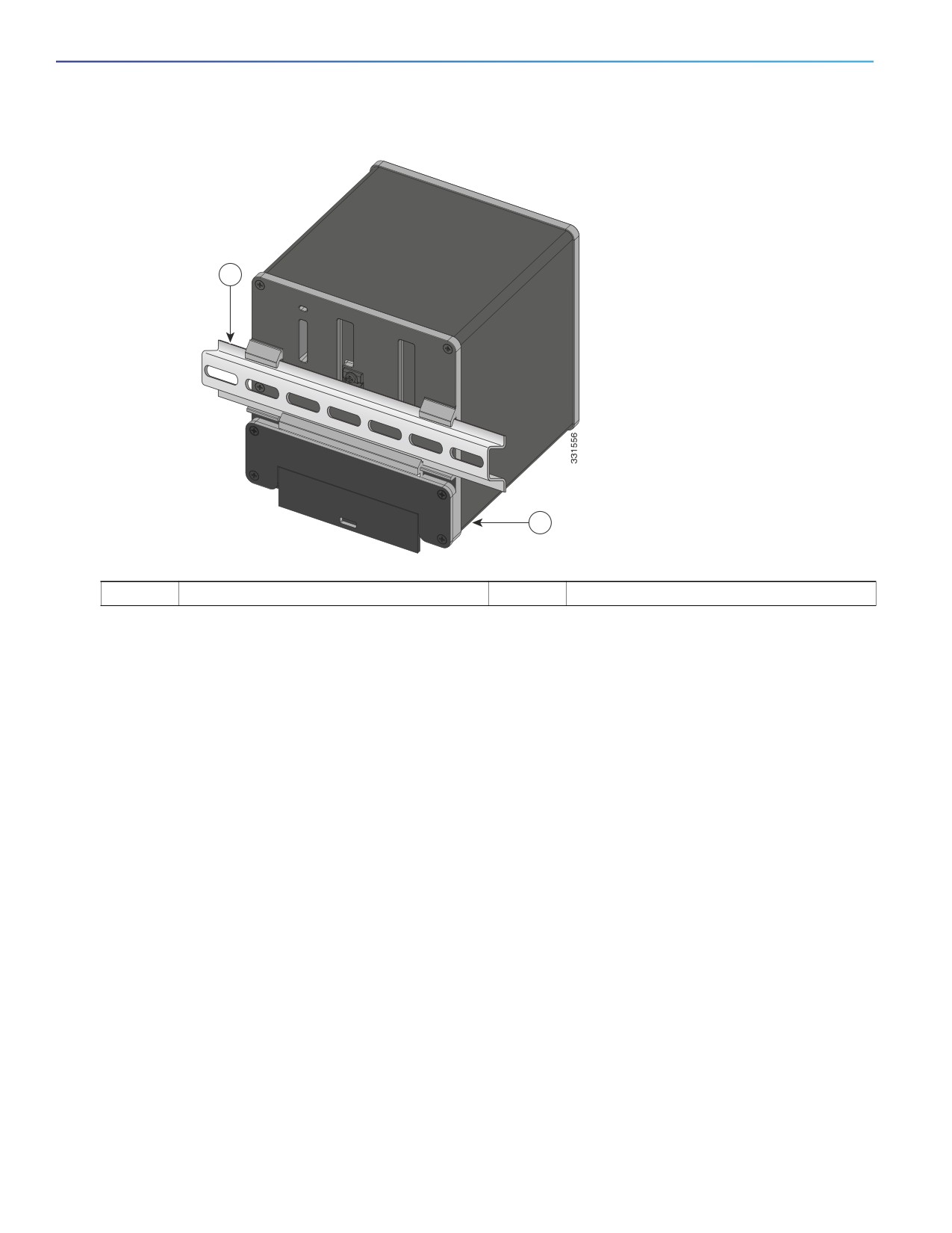
1. Position the rear panel of the switch directly in front of the DIN rail, making sure that the DIN rail fits in the space
between the two hooks near the top of the switch and the spring-loaded latch near the bottom.
2. Holding the bottom of the switch away from the DIN rail, place the two hooks on the back of the switch over the top
of the DIN rail.
Caution: Do not stack any equipment on the switch.
29
Switch Installation
Installing the Switch
Figure 14
Position the Hooks Over the DIN Rail
1
2
1
DIN Rail
2
Switch
3. Push the switch toward the DIN rail to cause the spring-loaded latch at the bottom rear of the switch to move down,
and snap into place.
After the switch is mounted on the DIN rail, connect the power and alarm wires, as described in Connecting Alarm
Circuits, page 31.
For configuration instructions about the CLI setup program, see Configuring the Switch with the CLI-Based Setup
Program, page 45.
Note: For instructions on how to remove the switch from a DIN rail, see Removing the Switch from a DIN Rail, page 30.
Removing the Switch from a DIN Rail
To remove the switch from a DIN rail, follow these steps:
1. Ensure that power is removed from the switch, and disconnect all cables and connectors from the front panel of the
switch.
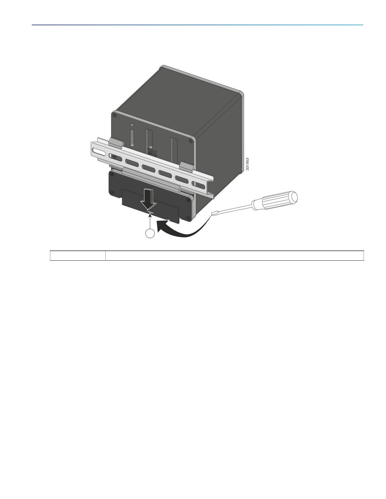
2. Insert a tool such as a flathead screwdriver in the slot at the bottom of the spring-loaded latch and use it to release
the latch from the DIN rail. See Figure 15 on page 31.
3. Pull the bottom of the switch away from the DIN rail, and lift the hooks off the top of the DIN rail. See Figure 15 on
page 31.
30
Switch Installation
Connecting Alarm Circuits
Figure 15
Releasing the Spring-Loaded Latch from the DIN Rail
1
1
Push latch down
4. Remove the switch from the DIN rail.
Connecting Alarm Circuits
After the switch is installed, you are ready to connect the DC power and alarm connections.
Wiring the Protective Ground and DC Power for Alarm Circuits, page 31
Wiring the External Alarms, page 31
Wiring the Protective Ground and DC Power for Alarm Circuits
For instructions on grounding the switch and connecting the DC power, see the Grounding the Switch, page 19.
Wiring the External Alarms
The switch has two alarm input and one alarm output relay circuits for external alarms. The alarm input circuits are
designed to sense if the alarm input is open or closed relative to the alarm input reference pin. Each alarm input can be
configured as an open or closed contact. The alarm output relay circuit has a normally open and a normally closed
contact.
31

Switch Installation
Connecting Alarm Circuits
Alarm signals are connected to the switch through the six-pin alarm connector. Three connections are dedicated to the
two alarm input circuits: alarm input 1, alarm input 2, and a reference ground. An alarm input and the reference ground
wiring connection are required to complete a single alarm input circuit. The three remaining connections are for the alarm
output circuit: a normally open output, a normally closed output, and a common signal. An alarm output and the common
wiring connection are required to complete a single alarm output circuit.
The labels for the alarm connector are on the switch panel and are displayed below.
Label
Connection
NO
Alarm Output Normally Open (NO) connection
COM
Alarm Output Common connection
NC
Alarm Output Normally Closed (NC) connection
IN2
Alarm Input 2
REF
Alarm Input Reference Ground connection
IN1
Alarm Input 1
Warning: Explosion Hazard—Do not connect or disconnect wiring while the field-side power is on; an electrical arc
can occur. This could cause an explosion in hazardous location installations. Be sure that power is removed or that
the area is nonhazardous before proceeding. Statement 1081
Caution: The input voltage source of the alarm output relay circuit must be an isolated source and limited to less
than or equal to 24 VDC, 1.0 A or 48 VDC, 0.5 A.
Note: Wire connections to the power and alarm connectors must be UL- and CSA-rated, style 1007 or 1569 twisted-pair
copper appliance wiring material (AWM) wire (such as Belden part number 9318).
To wire the switch to an external alarm device, follow these steps:
1. Remove the captive screws that hold the alarm connector on the switch, and remove the connector from the switch
chassis. See Figure 16 on page 33.
32
///////////////////////////////////////