KAWASAKI ROBOTS. ORIGINAL INSTRUCTION (v1.05) - page 6
 

  Index      Manuals     KAWASAKI ROBOTS. ORIGINAL INSTRUCTION (EN) v1.05


Search            copyright infringement  


Content      ..     4      5      6     


KAWASAKI ROBOTS. ORIGINAL INSTRUCTION (v1.05) - page 6


Hardware Specification 

162 


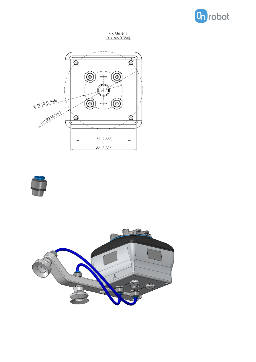
The  Push-in Fittings  are  used to  attach  4  mm  vacuum tubes to  create customized configuration that 
required remote vacuum. In most cases, this size is enough for generating the needed vacuum from the 
pump in the gripper. 


The commercial name of the Push-in Fittings is Fitting QSM-G1/8-4-I-R in case some more units need to 
be purchased. 

An example of a customized configuration with a homemade adaptor plate and remote vacuum is shown 
below. 


Hardware Specification 

163 


The image below shows how the push-in fittings and the normal fittings are communicated. 


Payload 

The lifting capacity of the VG grippers depends primarily on the following parameters: 


Vacuum cups 


Vacuum 


Air flow 


Vacuum Cups 

Choosing the right vacuum cups for your application is essential. The VG grippers come with common 15, 
30 and 40  mm silicone vacuum cups (see table below) which are good for hard and flat surfaces, but not 
good for uneven surfaces and it might leave microscopic traces of silicone on the  workpiece which can 
cause issues with some types of painting processes afterwards. 

      Image 

External Diameter 
[mm] 

Internal Diameter 
[mm] 

Gripping Area 
[mm2] 


15 

110 


30 

200 


40 

12 

450 


Hardware Specification 

164 

For non-porous materials, the OnRobot suction cups are highly recommended. Some of the most common 
non-porous materials are listed below: 


Composites 


Glass 


High density cardboard 


High density paper 


Metals 


Plastic 


Porous materials with a sealed surface 


Varnished wood 


In an ideal case, working with non-porous material workpieces where there are no air flow going through 
the workpiece, the table below shows the number of cups and the cup  size needed depending on the 
payload (workpiece mass) and the vacuum used. 


Number of Cups needed for non-porous materials depending on payload and vacuum: 


NOTE: 


15mm 


30mm 


40mm 

Payload 
(kg) 

Vacuum (kPa) 


Vacuum (kPa) 


Vacuum (kPa) 

20 

40 

60 

75 


20 

40 

60 

75 


20 

40 

60 

75 

4  


14 


11 


12 


14 


15 


12 


10 


14 

11 


12 


10 

16 

13 


13 


12 

15 


15 

10 


14 


12 


15 

10 


13 

10 


11 


14 

11 


12 


15 

12 


10 

13 


16 

13 


11 

14 


14 


12 

15 


15 


13 

Hardware Specification 

165 


To use more than 7 (15mm), 4 (30mm) or 3 (40mm) vacuum cups with 
the VGC10 a customized adaptor plate is needed. 


The table above is created with  the following formula that  equalizes the lifting  force with the payload 
considering 1.5g of acceleration. 

Amount

Cups

 . Area

Cup

[mm} = 19600

Payload [kg]

Vacuum [kPa]


It is often a good idea to use more vacuum cups than needed, to accommodate for vibrations, leaks and 
other unexpected conditions. However, the more vacuum cups, the more air leakage (air flow) is expected 
and the more air is moved in a grip resulting in longer gripping times. 

When using porous materials, the vacuum that can  be achieve by using the OnRobot suction cups will 
depend on the material itself and will be between the range stated in the specifications. Some of the most 
common non-porous materials are listed below: 


Fabrics 


Foam 


Foam with open cells 


Low density cardboard 


Low density paper 


Perforated materials 


Untreated wood 


See the table below with general recommendations, in case other suction cups are needed for specific 
materials. 


Workpiece surface 

Vacuum cup shape 

Vacuum cup material 

Hard and flat 

Normal or dual lip 

Silicone or NBR 

Soft plastic or plastic bag 

Special plastic bag type 

Special plastic bag type 

Hard but curved or uneven 

Thin dual lip 

Silicone or soft NBR 

To be painted afterwards 

Any type 

NBR only 

Varying heights 

1.5 or more bevels 

Any type 


NOTE: 

It  is  recommended to  consult  a  vacuum  cup  specialist  to  find  the 
optimal vacuum cup where the standard types are insufficient. 


Hardware Specification 

166 

Fittings and Blind Screws. 

It is possible to change suction cups simply by pulling them off the fittings. It might be a bit challenging to 
remove the 15 mm Diameter vacuum cups. As suggestion try to stretch the silicon to one of the sides and 
then pull it out. 

Unused holes can be blinded using a blind screw, and each fitting can be changed to a diffe rent type to 
match  the  desired suction  cup.  The  fittings  and  the  blinding  screws are  mounted or  dismounted by 
screwing (2Nm tightening torque) or unscrewing them with the provided 3 mm Allen key.  


The thread size is the commonly used G1/8”; allowing f

or standard fittings, blinders and extenders to be 

fitted directly to the VG grippers. 


Hardware Specification 

167 

Vacuum 

Vacuum is defined as the percentage of absolute vacuum achieved relative to atmospheric pressure, i.e.: 

The vacuum in kPa setting is the target vacuum. The pump will  run at full speed until the target vacuum 
is achieved, and then run at a lower speed necessary to maintain the target vacuum.  

The  pressure  in  the  atmosphere varies  with  weather, temperature  and  altitude.  The  VG  g rippers 
automatically compensate for altitudes up to 2km, where the pressure is about 80% of sea level.  


Air flow 

Air  flow is  the amount of air  that must be pumped to maintain the target vacuum. A completely tight 
system will not have any air flow, whereas real life applications have some smaller air leakages from two 
different sources: 


Leaking vacuum cup lips 


Leaking workpieces 


The smallest leak under a vacuum cup can be hard to find (see picture below).  


Leaking workpieces can be even harder to identify. Things that look completely tight might not be tight at 
all. A typical example is coarse cardboard boxes. The thin outer layer is often requiring a lot of air flow to 
create a pressure difference over it (see figure below). 


Therefore, the users must be aware of the following: 


VG grippers are not suitable for most uncoated, coarse cardboard boxes.  

% vacuum 

Bar 

kPa 

inHg 

Typically used for 

0% 

0.00rel. 
1.01 abs. 

0.00rel. 
101.3  abs. 

0.0rel. 
29.9 abs. 

No vacuum / No lifting capacity 

20% 

0.20rel. 
0.81 abs. 

20.3rel. 
81.1 abs. 

6.0rel. 
23.9 abs. 

Cardboard and thin plastics 

40% 

0.41rel. 
0.61 abs. 

40.5rel. 
60.8 abs. 

12.0rel. 
18.0 abs. 

Light workpieces and long suction cup life span 

60% 

0.61rel. 
0.41 abs. 

60.8rel. 
40.5 abs. 

18.0rel. 
12.0 abs. 

Heavy workpieces and strongly secured grips 

80% 

0.81rel. 
0.20 abs. 

81.1rel. 
20.3 abs 

23.9rel. 
6.0 abs. 

Max. vacuum. Not recommended 

Hardware Specification 

168 


Extra attention must be paid to leakages, e.g. vacuum cup shape and surface roughness  


The air flow capability of a VG grippers is shown in the graph below:  


NOTE: 

The easiest way to check if a cardboard box is sufficiently tight is simply 
to test it using the VG grippers. 

A  high  vacuum  percentage  setting  does  not  give  a  higher  lifting 
capacity  on  corrugated  cardboard.  In  fact,  a  lower  setting  is 
recommended, e.g. 20%. 

A low vacuum setting results in less air flow and less friction below the 
vacuum cups. This means VG gripper filters and vacuum cups will last 
longer. 


VG pump, air flow performance


N

l/

m

in

Vacuum percentage


Hardware Specification 

169 

9.2


Mechanical Drawings 

9.2.1


Adapter plate(s) 


Hardware Specification 

170 

Adapter B 


A

ll 

d

ime

n

si

o

n

ar

e

 in

 mm 

an

d

 [i

n

ch

e

s]

Hardware Specification 

171 


Adapter C 


A

ll 

d

ime

n

si

o

n

ar

e

 in

 mm 

an

d

 [i

n

ch

e

s]

Hardware Specification 

172 


Adapter D 


A

ll 

d

ime

n

si

o

n

ar

e

 in

 mm 

an

d

 [i

n

ch

e

s]

Hardware Specification 

173 


Adapter E 


Hardware Specification 

174 


9.2.2


Mountings 


Quick Changer - Robot side .............175 


Quick Changer for I/O - Robot side ..176 


Dual Quick Changer ........................177 


HEX-E/H QC ....................................178 


Hardware Specification 

175 

Quick Changer - 

Robot side 


* Distance from Robot flange interface to OnRobot tool. 

All dimensions are in mm and [inches]. 


Hardware Specification 

176 

Dual Quick Changer 


* Distance from Robot flange interface to OnRobot tool  

All dimensions are in mm and [inches]. 


Hardware Specification 

177 

HEX-E/H QC 


* Distance from Robot flange interface to OnRobot tool  

All dimensions are in mm and [inches]. 


Hardware Specification 

178 

9.2.3


Tools 


Gecko .............................................179 


RG2-FT ...........................................180 


RG2 ................................................181 


RG6 ................................................182 


VG10 ..............................................183 


VGC10 ............................................185 


Quick Changer - Tool side ................187 


Hardware Specification 

179 

Gecko 


All dimensions are in mm and [inches]. 


Hardware Specification 

180 

RG2-FT 


All dimensions are in mm and [inches]. 


Hardware Specification 

181 

RG2 


All dimensions are in mm and [inches]. 


Hardware Specification 

182 

RG6 


All dimensions are in mm and [inches]. 


Hardware Specification 

183 

VG10 


All dimensions are in mm and [inches]. 

Hardware Specification 

184 


All dimensions are in mm and [inches]. 


Hardware Specification 

185 

VGC10 


All dimensions are in mm and [inches]. 

Hardware Specification 

186 


All dimensions are in mm and [inches]. 


Hardware Specification 

187 

Quick Changer - 

Tool side 


All dimensions are in mm and [inches]. 


Hardware Specification 

188 

9.3


Center of Gravity 


COG, TCP, and weight parameters of the single devices (without any mounting/adapter): 

HEX-E/H QC 

Coordinate system 

TCP [mm] 

Center of Gravity [mm] 

Weight 


X=0 
Y=0 
Z=50 

cX=0 
cY=5 
cZ=20 

0.35 kg 

0.77 lb 


Gecko 

Coordinate system 

TCP [mm] 

Center of Gravity [mm] 

Weight 


X=0 
Y=0 
Z=187 

cX=0 
cY=0 
cZ=113 

2.83 kg 

6.10 lb 


RG2-FT 

Coordinate system 

TCP [mm] 

Center of Gravity [mm] 

Weight 


X=0 
Y=0 
Z=205 

cX=0 
cY=0 
cZ=65 

0.98 kg 

2.16 lb 


* Mounted at 0˚


RG2 

Coordinate system 

TCP [mm] 

Center of Gravity [mm] 

Weight 


X=0 
Y=0 
Z=200 

cX=0 
cY=0 
cZ=64 

0.78 kg 

1.72 lb 

* Mounted at 0˚


Hardware Specification 

189 


RG6 

Coordinate system 

TCP [mm] 

Center of Gravity [mm] 

Weight 


X=0 
Y=0 
Z=250 

cX=0 
cY=0 
cZ=90 

1.25 kg 

2.76 lb 

* Mounted at 0˚


VG10 

Coordinate system 

TCP [mm] 

Center of Gravity [mm] 

Weight 


X=0 
Y=0 
Z=105 

cX=15 
cY=0 
cZ=54 

1.62 kg 

3.57 lb 

* With arms folded back 


VGC10 

Coordinate system 

TCP [mm] 

Center of Gravity [mm] 

Weight 


X=0 
Y=0 
Z=7 

cX=-1 
cY=-1 
cZ=37 

0.814  kg 

1.79 lb 

* With no attachments 


Maintenance 

190 

10


Maintenance 


WARNING: 

An  overall  inspection of  the  OnRobot's  End  of  Arm  Tooling  must  be 
performed regularly and at  least once every 6 months. This inspection 
must include but is not limited to check for defective material and clean 
gripping surfaces.   

Use  original  spare  parts,  and  original  service  instructions  for  the 
OnRobot's End of Arm Tooling and the robot. Failure to comply with this 
precaution can cause unexpected risks, resulting in severe injury. 


If you have questions regarding spare parts and  repair, please visit our  website  

www.onrobot.com

 to 

contact us. 


Gecko .............................................190 


RG2/6.............................................192 


RG2-FT ...........................................192 


VG10 / VGC10.................................192 


Gecko 

Gecko  Gripper  pads  are  made  from  a  precision  cast  silicone  or  polyurethane  film  with  a  gecko 
microstructure. Contact with sharp objects may damage the pad surface and impair function. The Gecko 
Gripper performance is maximized when the pads are clean and dry.  The pads can collect dust, so it is 
best to use the Gecko Gripper in a clean environment and/or establish a routine cleaning schedule.  


Replacing the Gripper Pads 

Gecko Gripper pads are designed to last for 200,000-300,000  cycles under typical operating conditions. If 
the pads do not seem to be gripping properly, even with routine cleaning (see table in the previous page), 
we recommend fully replacing the gripper pads. 

To replace the gripper pads, use the provided pad removal tool. 

Step 1:  Move  gripper  pads  to  the  maximum  extruded  setting  such  that  the  pads  are  maximally 
exposed/visible. 

Part 

Description of Maintenance 

Frequency 

Pad Cleaning 

Routine cleaning: 

Cleaning Station 

Dependent on  operating  conditions. 
Guidelines are: 

See Cleaning Station User Guide 


Pad Wear 

Replacement due to wear 

150000 

  200000  for  HIGH  preload 

operation 

200000 

  250000  for  LOW  preload 

operation 

Maintenance 

191 


Step 2:  Insert the edge of the pad removal tool between the shiny silver plate of the pads and the dull 
backing plate. Leverage the pad removal tool against the gripper housing to pry off the used pad. Repeat 
for all pads. 


Step 3:  To install  new replacement pads, align the notch of the pad with the tab in the mounting hole. 
Push the pad into the gripper until there are no gaps between the shiny silver pad plate and backing plate. 


Maintenance 

192 

RG2/6 


WARNING: 

An overall inspection of the PLd CAT3 Safety Buttons must be performed 
regularly and at least once every 6 months.  


RG2-FT 


WARNING: 

Please clean the proximity sensor surface regularly with low pressure 
compressed air (<5 bar) from a 5 cm distance. For stronger 
contamination use isopropyl alcohol with a soft cotton swab to keep it 
clean.  


VG10 / VGC10 

The VG grippers are equipped with one filter for each suction cup socket, and one filter for the exhaust. 
How often the filters need to  be changed depends on the nature of the work piece and  the working 
environment. The VG grippers automatically de-dust the filters every time a grip  is  released. However, 
particles can eventually get stuck and build up inside the filter, lowering the VG  grippers performance.  

A filter service kit is available, which include both new filters and tools needed. 

Filter service kit for VG10, PN 100064 

Filter service kit for VGC10, PN 103757 


Neither use nor power on the VG grippers without filters. Dust, hair and larger particles can get stuck in 
pump membranes and valve seats, causing permanent damage to the VG grippers. 


DANGER: 

Identify how often the filters need service and schedule maintenance 
with a fixed period short enough to ensure a firm grip at all times. 

An overall  inspection of the VG grippers must be performed regularly 
and at least once every 6 months. 

Never power the  VG grippers  without filters  or  with  filters  mounted 
incorrectly. Failure to comply with this precaution can cause irreversible 
failure of pump or valves. 


Warranties 

193 

11


Warranties 

11.1


Patents 

Products of OnRobot A/S are protected by several patents; some still in global publication process (Patents 
pending). All manufacturers of copies and similar products violating any patent claims will be prosecuted. 

11.2


Product Warranty 

Without prejudice to any claim  the user (customer) may have in  relation to the dealer or retailer, the 

customer shall be granted a manufacturer’s warranty under the condition

s set out below: 

In the case of new devices and their components exhibiting defects resulting from manufacturing and/or 
material faults within 12 months of entry into service (maximum of 15  months from shipment), OnRobot 
A/S shall  provide the necessary spare parts, while the customer (user) shall  provide working hours to 
replace the spare parts, either replace the part with another part reflecting the current state of the art, 
or  repair  the said  part. This  warranty shall  be invalid  if  the device defect is  attributable to  improper 
treatment and/or failure to comply with information contained in the user guides. This warranty shall not 
apply  to  or  extend to  services performed by the authorized dealer or  the customer themselves  (e.g. 
installation,  configuration,  software  downloads).  The  purchase  receipt,  together  with  the  date  of 
purchase, shall be required as evidence for invoking the warranty. Claims under the warranty must be 
submitted  within  two  months  of  the  warranty  default  becoming  evident. Ownership of  d evices  or 
components replaced  by  and  returned to  OnRobot  A/S shall  vest  in  OnRobot A/S. Any  other  claims 
resulting out of or in  connection with the device shall  be excluded from this  warranty. Nothing in this 
warranty shall  attempt to limit  or  exclude a cu

stomer’s statutory rights nor the manufacturer’s liability 

for  death or  personal  injury resulting  from its  negligence. The  duration  of the  warranty shall  not  be 
extended by services rendered under the terms of the warranty. Insofar as no warranty default e xists, 
OnRobot A/S reserves the right to charge the customer for replacement or repair. The above provisions 
do  not imply  a  change in  the  burden of  proof to  the detriment of  the customer. In  case  of a  device 
exhibiting defects, OnRobot A/S shall not be liable  for any indirect, incidental, special or consequential 
damages, including  but not  limited to, lost  profits, loss of use, loss of production or  damage to other 
production equipment. 

In case of a device exhibiting defects, OnRobot A/S shall not cover any consequential damage or loss, such 
as loss of production or damage to other production equipment. 

11.3


Disclaimer 

OnRobot A/S continues to improve reliability and performance of its products, and therefore reserves the 
right to upgrade the product without prior warning. OnRobot A/S ensures that the content of this manual 
is precise and correct but takes no responsibility for any errors or missing information.  


Content      ..     4      5      6