KAWASAKI ROBOTS. ORIGINAL INSTRUCTION (v1.05) - page 3
 

  Index      Manuals     KAWASAKI ROBOTS. ORIGINAL INSTRUCTION (EN) v1.05


Search            copyright infringement  


Content      ..     1      2      3      4      ..


KAWASAKI ROBOTS. ORIGINAL INSTRUCTION (v1.05) - page 3


Installation 

66 

6.3


Wiring 

Four kind of cables have to be connected to wire the system properly: 


Tool data cable between the tool(s) and the Compute Box 


The provided Digital I/O wires between the Computer Box and the robot controller 


Ethernet communication cable between the Compute Box and your computer 


Power supply of the Compute Box 


6.3.1


Tool data 

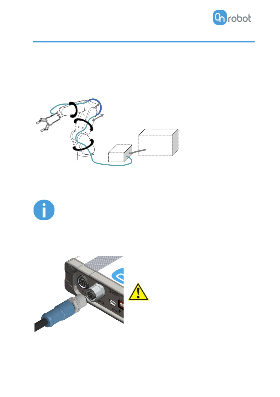
Connect the data cable to the tool(s) then route the cable (blue line) to the Compute Box (CB) and use the 
supplied Velcro tape (black) to fix it.  


NOTE: 

Leave some extra cable length around the joints so that the cable is not 
pulled when the robot moves. 

Also make sure that the cable bending radius is minimum 40mm (for the 
HEX-E/H QC it is 70mm) 


Then, connect the other end to the Compute Box's DEVICES connector. 


CAUTION: 

Use only original OnRobot tool data cables. 


6.3.2


Digital I/O wires 

For KAWASAKI robots the two most recent controllers are:  


the F-Series which uses a DX40-50P connector for I/O interface 

CB


bending radius


extra length


Robot  

controller


Installation 

67 


and E-Series which uses a 37-pin D-Sub (M/F) connector.  

The GPIO board in  the control cabinet can be used be used to connect the Compute Box to the robot 
controller. 


NOTE: 

It  is  HIGHLY recommended to purchase the appropriate connector &  harness parts before 
installing the gripper and I/O converter. There are no screw terminals for the I/O terminal in 
the controller. The I/O connections for the F-Series controller can be soldered, but the solder 
points are very small. The I/O connections for the E-Series controller cannot be soldered and 
require using a DB37 connector. 
 

Controller 

Description 

Sample Vendor 

F-Series (2AB/AE Board) 

HIROSE DX40-50P Connector 

Digikey, Mouser 

DX-50-CV Connector Backshell 

E-Series (1TW Board) 

DB37 (M & F) Connector   

Amazon, Digikey 


Make sure that the robot is powered off completely.  

First locate the DB37  connector for E-Series on the back side of the cabinet or the DX40-50P connector 
for the F-Series on the side of the cabinet. Prepare the mating connectors. 

Check your digital I/O module installed in the control cabinet and configure the Compute Box DIP switches 
(red)  accordingly: 


For 

PNP

  type set the 1. and 2. DIP switches to OFF position (down). 


For 

NPN

 type set the 1. and 2. DIP switches to ON position (up). 


DIP switch 1: Digital Input mode 

DIP switch 2: Digital Output mode 


NOTE: 

Do not change the DIP switch 3 and 4 otherwise the network settings will 
be changed. 


(Please refer to the robot manual to check whether it is an NPN or a PNP type.)  


Installation 

68 


NOTE: 

The Kawasaki robot controller has an XGPIO board that determines whether the robot 
is configured for PNP or NPN.  


For the F-Series, the XGPIO board (2AB/AE) is in PNP configuration by default and 
can  be changed by setting jumper JP8  on  the board (refer to  the F  Controller 
External IO Manual for more information).  


For  the E-Series, robot PNP/NPN is determined by the XGPIO board (1TW);  to 

change configurations, the controller’s XGPIO board must be swapped out.


Plug in the supplied green pluggable connectors. 

 The supplied connector types are: 

2 x Phoenix Contact MC 1,5/8-ST-3,5 Terminal Block 

1 x Phoenix Contact MC 1,5/6-ST-3,5 Terminal Block 


Wire the digital I/O wires from the Compute Box to the robot. 


DO1-8

: Digital outputs of the Compute Box (signals from the grippers/sensor to the robot)  

DI1-8

: Digital inputs of the Compute Box (signals from the robot to the grippers/sensor) 

GND

: To be used to have a common ground between the robot and the gripper/sensor 


It is recommended to connect all 8 inputs and 8 outputs for simplicity. 


CAUTION: 

If some of the DO1-8 or DI1-8 wires will not be connected, make sure to 
unscrew it from the terminal block to avoid an accidental short circuit. 


CAUTION: 

The 24V  and GND pins are only Reference Voltage Output. It cannot be 
used to power any equipment. 

 It is recommended to use the supplied wires only. If it is necessary to use 
different wire, use one that is shorter than 3 m. 


Connect the Compute Box inputs  to  the robot outputs and  the Compute Box outputs to   robot 
inputs. 

Installation 

69 

For simplicity, it is recommended to map the pins in order: 

DO1 to the robot's Digital  input 1 

DO2 to the robot's Digital  input 2 


DO8 to the robot's Digital  input 8 

DI1 to the robot's Digital  output 1 

DI2 to the robot's Digital  output 2 


DI8 to the robot's Digital  output 8 


E-Series 

List of the important pins of the CN2 and CN4 connectors:  

Rear view of the male 37  pin sub-d connector: 


Rear view of the female 37 pin sub-d connector: 


Pin 

Description 

Pin 

Description 

CN4 - 1 

Digital input 1 

CN2 - 1 

Digital output 1 

CN4 - 2 

Digital input 2 

CN2 - 2 

Digital output 2 

CN4 - 3 

Digital input 3 

CN2 - 3 

Digital output 3 

CN4 - 4 

Digital input 4 

CN2 - 4 

Digital output 4 

CN4 - 5 

Digital input 5 

CN2 - 5 

Digital output 5 

CN4 - 6 

Digital input 6 

CN2 - 6 

Digital output 6 

CN4 - 7 

Digital input 7 

CN2 - 7 

Digital output 7 

CN4 - 8 

Digital input 8 

CN2 - 8 

Digital output 8 


CN4 - 18  

IN-COM1 

CN2 - 36 

OUT-COM1 


Please note which pin you used during the wiring, in a later step it is going to be needed for the mapping. 

To have a common signal ground the following two pins needs to be wired together: 

Pins from 

Pins to 

Description 

Compute Box - GND 

CN4 - 18 

Compute Box GND to IN-COM1 

Compute Box - GND 

CN2 - 36 

Compute Box GND to OUT-COM1 


Installation 

70 

F-Series 

List of the important pins of the DX40-50P connector:  


Pin 

Description 

Pin 

Description 

Digital input 1 

31 

Digital output 1 

Digital input 2 

32 

Digital output 2 

Digital input 3 

33 

Digital output 3 

10 

Digital input 4 

34 

Digital output 4 

11 

Digital input 5 

35 

Digital output 5 

12 

Digital input 6 

36 

Digital output 6 

13 

Digital input 7 

37 

Digital output 7 

14 

Digital input 8 

38 

Digital output 8 


IN-COM1 

30 

OUT-COM1 


Please note which pin you used during the wiring, in a later step it is going to be needed for the mapping. 

To have a common signal ground the following two pins needs to be wired together: 

Pins from 

Pins to 

Description 

Compute Box - GND 

Compute Box GND to IN-COM1 

Compute Box - GND 

30 

Compute Box GND to OUT-COM1 


6.3.3


Ethernet cable 

Connect the provided Compute Box (ETHERNET connector) and your computer with the 
supplied UTP cable. 

 
This connection is only needed for programming. 


Installation 

71 


CAUTION: 

Use only original  OnRobot ethernet cables or replace it  with one 
that is shielded and no more than 3 meter long. 


WARNING: 

Check and make sure that the Compute Box enclosure (metal) and the 
robot  controller  enclosure  (metal)  are  not  connected  (no  galvanic 
connection between the two). 


6.3.4


Power supply 

Connect the supplied power supply to the Compute Box 24V 
connector.  


NOTE: 

To  disconnect  the  power  connector,  make 
sure to pull the connector housing (where the 
arrows are shown) and not the cable.  


CAUTION: 

Use only original OnRobot power supplies. 


Finally, power up the power supply that will power the Compute Box and the connected Tool(s).  


Operation 

72 

7


Operation 


NOTE: 

It is assumed that the Installation has finished successfully. If not, first do 
the installation steps in the previous section. 


7.1


Overview 

OnRobot WebLogic  requires to  be  programmed first  with  the  help  of  a  computer connected to  the 
Compute box. Then it can run standalone without any Ethernet connection. 

Steps to program it: 


Setup the Compute Box's Ethernet interface and connect to the Compute Box 


Open the Web Client on your computer to access the WebLogic menu 


Write your program in the WebLogic menu 


The following subsections will guide you through these steps. 


Operation 

73 

7.2


Ethernet Interface setup 

A proper IP address must be set for  the Compute Box and  the robot/computer to be able  to use the 
Ethernet interface. There are three ways how it could be configured (using the DIP switch 3 and 4): 


Auto mode

 (factory default)  

This is the easiest way of getting the IP addresses to be configured for both the Compute Box and 
the  robot/computer. It is  recommended to  start  with  this  mode, so  this  is  the   factory  default 
setting. 


Fixed IP mode

 (192.168.1.1) 

If the 

Auto mode

 does not work, use this mode to have a fixed IP for the Compute Box. This requires 

a manual IP address configuration for the robot/computer. (This mode could also be used to reset 
the IP address to a known value if the Compute Box become unreachable in 

Advanced mode

.) 


Advanced mode

 (any static IP/subnet mask) 

If the Fixed IP address (192.168.1.1) is already in use in your network or a different subnet needs to 
be configured, in this mode the IP address and subnet mask can be changed to any value. This also 
requires a manual IP address configuration for the robot/computer. 


NOTE: 

To change between modes, first change the DIP switches and then the 
Compute Box power needs to be cycled for the changes to take effect. 


Auto mode 

Use the factory default settings (DIP switch 3 and 4 in OFF position). 

In this case, the Compute Box has both Dynamic Host Configuration Protocol (DHCP) client, 
and DHCP server enabled.  

DHCP  Client  enabled

  means,  Compute  Box  will  automatically  obtain  ("get") IP  address  FROM  the 

connected robot/computer if that is capable of assigning ("give") IP to the Compute Box.  


DHCP Server enabled

 means, Compute Box will automatically assign ("give") IP address TO the connected 

robot/computer if that was configured to obtain ("get") IP address automatically.  


NOTE: 

The assigned IP range is 192.168.1.100-105  (with subnet mask 255.255.255.0). 

If  the Compute Box  is  used in  a  company  network where a  DHCP  server is 
already in use, it is recommended to disable the DHCP server of the Compute 
Box by setting DIP switch 4 to the ON position. 

If no IP was assigned to the Compute Box within a minute, it will automatically 
get a fallback IP address (192.168.1.1). 


NOTE: 

If the Compute Box was in 

Advanced mode

, first reset the IP setting by 

switching to 

Fixed IP mode

 and then switch back to 

Auto mode


Operation 

74 

Fixed IP mode 

Set the DIP switch 3 and 4 in ON position and cycle the power for the changes to take effect.  

In  this  case  the  IP  address  of  the  Compute  Box  is  set  to  192.168.1.1  (subnet  mask  is 
255.255.255).  Both the DHCP Client and Server options are disabled. 

Make  sure  to  set  the  robot/computer  IP  address  manually.  To  have  a  proper  communication  the   
robot/computer IP address must be in the range of 192.168.1.2   -  192.168.1.254. 

Example robot/computer setting: 

IP address: 192.168.1.2 

Subnet mask: 255.255.255.0 

Other settings like Gateway, DNS Server, etc. could be kept empty or set to 0.0.0.0. 


Advanced mode 

Set the DIP switch 3 in OFF and DIP switch 4 in ON position and cycle the power for the changes 
to take effect. 


In this case the IP address of the Compute Box could be set to any value by using the Web Client. For more 
details see section 

Configuration menu

In this mode, the DHCP server option is disabled. 

Make sure to have a matching IP setting to your robot/computer network for a proper communication.  


NOTE: 

If the Compute Box become unreachable (due to improper or forgotten 
IP settings), switch to 

Fixed  IP mode

 to reset the IP setting. 


Operation 

75 

7.3


Web Client 

To access the Web Client on your computer first the Ethernet interface needs to be set up to have a proper 
communication between your computer and the Compute Box. It is recommended to use Auto mode (for 
further details see section 

Ethernet Interface setup

). 

Then do the following steps: 


Connect the Compute Box to your computer with the supplied UTP cable. 


Power the Compute Box with the supplied power supply 


Wait one minute for the Compute Box LED to turn from blue to green.  


Open a  web browser on your computer and type in  the IP address of the Compute Box (factory 
default is 192.168.1.1). 


The Sign-in page opens: 


The factory default administrator login is: 

Username

: admin 

Password

: OnRobot 


Operation 

76 

For the first login a new password needs to be entered: (password must be at least 8 characters long)  


Once logged in you can access top menus. Select 

WebLogic

 menu. 


Operation 

77 

7.4


OnRobot WebLogic menu 

There are two tabs to choose from: 


Browser - 

manage (import/export, etc.) the WebLogic programs 


Program Editor - 

create/edit or run WebLogic programs


In the following these two will be described. 

7.4.1


Browser 

This tab lists the WebLogic programs that are stored on the Compute Box. 


To create a new program, go to the 

Program Editor 

tab. 


To edit a stored program, click on the pencil icon and it will be loaded in the 

Program Editor


Any program can be deleted by clicking on the trash  icon. 


Programs can be exported to your computer by clicking on the down arrow  icon. 


Exported programs can be imported with the 

Import 

button. 


NOTE: 

The program name that are edited in the 

Program Editor 

is bolded. 


Operation 

78 

7.4.2


Program Editor 

This tab shows the currently edited WebLogic program. 

WebLogic programs contains 1 or more "rows". 

A row contains conditions (blue part) and commands (gray part) like this:  

 (

If

)       DI1=1      

 (

Then

)        RG2-Width=77 (force=20N) 


(If the robot sets the Digital Input 1 (DI1) of the Compute Box to high, 

then

 open the RG2 gripper 

to 77 mm.) 

Another row in a program can be like this: 

 (

If

)       DI1=0       

 (

Then

)        RG2-Width=20 (force=40N) 


(If the robot sets the Digital  Input 1 (DI1) of the Compute Box to low, 

then

 close the RG2 gripper to 

20 mm.) 

With the above two rows in a program an RG2/6 gripper could be operated (opened and closed) with a 
single Digital output of a robot, while the opening and closing width and force can be programmed to any 
value. 


To execute a WebLogic program first make sure to enter a program name and click on the 

Save

 button to 

store it and then click  on the 


Run

 button. 


Operation 

79 


NOTE: 

To make a program run automatically when the Compute Box is powered 
on just leave the program running while you power the Compute Box off. 


To start a new program, click on the 

New 

button. 


To add a new row, click  on the 

Add new conditions and commands


To delete a row, click on the 

icon. 


To move the row up or down click on the 

 icons. 


NOTE: 

Conditions and  commands  are  executed  from the top  to  the  bottom. 
Same commands at the bottom can override the ones at the top. 


To duplicate a row click on the 

 icon. 


To disable a row (not to be executed) uncheck the checkbox 

 next to the row number. 


The rows must have at least one condition and at least one command to be executed.  


Conditions 

Conditions are the input fields marked by blue. 

There are two types of conditions: 


Digital Input type -  like DI4=1 


Device specific value type - like HEX Fx > 10N 


These types of conditions can be combined with AND or OR logic to form a more complex condition:  

If

 ( DI4=1 ) 

OR

 (HEX Fx > 10 N 

AND

 HEX Fx < 20N ) 


Condition is true if Fx is between 10N and 20N or robot has signaled high in Digital Input 4.  


Digital inputs (DI1-DI8) can have the following three states: (click to cycle through the states)  


 - 

Don’t care (this bit is masked and will give true result for the bit)


 - give logic true if Input bit is low 


  -give logic true if Input bit is high 


Operation 

80 


NOTE: 

If no Digital Input type of condition is needed set DI1-DI8 to   don't care. 


For Device specific values first set the 

Select device

 by clicking  on the arrow   icon. 


NOTE: 

The list  contains only the connected devices. If you would like to 
select a device that is not currently connected check the 

Show all 

devices

 checkbox. 


For RG2/6, VG10 / VGC10 and Gecko there are three numbers after the device name: 


0

 - If the device is mounted on a Quick Changer or a HEX-E/H QC 


1

 - If the device is mounted on the Primary side of a Dual Quick Changer 


2

 - If the device is mounted on the Secondary side of a Dual Quick Changer 


NOTE: 

If a Device specific value type condition is not needed set it to 

-- Not selected -- 

and it will give true result. 


Commands 

Commands are the input fields marked with gray. 

There are two types of commands: 


Device specific value type - like 

 (set RG2 width 77  mm and with force = 20N) 


Digital Output type -  like DO4=1 

 (set Digital Output 4 to logic high) 


NOTE: 

Both types are always executed so make sure that the not relevant part 
is always set to   Don't change or 

-- Not selected --


For Device specific value first set the 

Select device

 by clicking on the arrow   icon. 


NOTE: 

The list  contains only the connected devices. If you would like to 
select a device that is not currently connected check the 

Show all 

devices

 checkbox. 


For RG2/6, VG10 / VGC10 and Gecko there are three numbers after the device name: 


0

 - If the device is mounted on a Quick Changer or a HEX-E/H QC 


1

 - If the device is mounted on the Primary side of a Dual Quick Changer 


2

 - If the device is mounted on the Secondary side of a Dual Quick Changer 


Operation 

81 

Digital outputs (DO1-DO8) can have the following three states: (click to cycle through the states)  


 - 

Don’t change


 - set the Output bit to logic low 


  - set the Output bit to logic high 


List of Device specific values 


Gecko .............................................. 81 


HEX-E/H QC ..................................... 82 


RG2/6.............................................. 82 


RG2-FT ............................................ 83 


VG10 / VGC10.................................. 83 


NOTE: 

Each device has an 

OnStart

 condition that becomes True only once the 

device  is  connected  or  the  program  is  started  and  then  becomes 
immediately False. This can be used to detect if a device is connected or 
set any initial value on program start. 


Gecko 

Conditions 

Description 

Preload 

Actual force applied to the pads [N] (below 50N it reads 0N) 

Ultrasonic 

Actual distance measured from the bottom of the gripper to the object.[mm]  

Pad position 

Actual position of the pads either 

In

 or 

Out


Pads worn 

If a Grip was detected and then object distance becomes more than 18mm 
(without the pads being pulled IN) the object is lost  so the Pads are 

Bad


otherwise reads 

Good

Busy 

Pads are in motion 

Grip 

While the pads are OUT if the 

Preload

 force is reached and the object distance 

is less than 18mm, then Grip becomes 

TRUE

 otherwise 

FALSE

. (resets to 

FALSE


by pulling the pads IN) 


Commands 

Description 

Pad position 

To pull the pads 

In

 or push the pads 

Out


Preload threshold 

To set the preload force limit that is used to detect a successful 

Grip

Available options are: 50N, 90N, 120N 

Reset error logs 

Clears the errors (e.g.: Pads worn) 


Operation 

82 


HEX-E/H QC 

Conditions 

Description 

Bias 

TRUE

 if the sensor has been zeroed (biased). 

F3D, T3D 

F3D

= √𝐹𝑥

2

+ 𝐹𝑦

2

+𝐹𝑧

2

 [N] 

T3D

= √𝑇𝑥

2

+ 𝑇𝑦

2

+𝑇𝑧

2

 [Nm] 

Fx, Fy, Fz, Tx, Ty, Tz 

Actual force [N] and torque [Nm] values 


Commands 

Description 

Bias 

Set to 

TRUE

 to zero the F/T sensor signals (not permanent, will revert on 

power reset) 


RG2/6 

Conditions 

Description 

Width 

Actual width of the gripper [mm]  

Busy 

True if the gripper is in motion (can only accept new commands when not 
busy) 

Grip 

Internal or external grip is detected. 

Safety pressed 

True if any of the gripper's safety switch is currently being pressed. 

Safety triggered 

True if any of the gripper's safety switch is triggered. 


Commands 

Description 

Width 

Set the gripper to a new width [mm] with a gripping force [N] 

Fingertip offset 

Set the fingertip offset from the inner side of the metal [mm]. Positive number 
means inward. 

Power cycle 

If safety switch stopped the gripper use this to get back to normal operation. 

Resets the tool power for a second. If another gripper is connected, that will also 
be powered off and powered on for a second. (Make sure that during power off 
no part to will be dropped.)  


Operation 

83 

RG2-FT 

Conditions 

Description 

Proximity (L,R) 

Actual values of the left and right fingertip proximity sensors [mm] 

Width


Actual width of the gripper [mm]  

Busy


True if the gripper is in motion (can only accept new commands when not 
busy) 

Grip 

Internal or external grip is detected.


FT Bias 

TRUE

 if the sensor has been zeroed (biased). 

Left and Right 
F3D,T3D 

F3D

= √𝐹𝑥

2

+ 𝐹𝑦

2

+𝐹𝑧

2

 [N] where Fx, Fy, Fz are the fingertip sensor force 

components 
T3D

= √𝑇𝑥

2

+ 𝑇𝑦

2

+𝑇𝑧

2

 [Nm] where Tx, Ty, Tz are the fingertip sensor torque 

components 

Both F3D,T3D 

The combined F3D and T3D acting on an object that the gripper gripped on 


Commands 

Description 

Width 

Set the gripper to a new width [mm] with a gripping force [N] 

Bias 

Set to 

TRUE 

to zero the F/T sensor signals (not permanent, will revert on 

power reset) 


VG10 / VGC10 

Conditions 

Description 

Actual vacuum A 

Actual vacuum B 

Actual vacuum level [0-80%] for channel A and channel B  


Commands 

Description 

Current limit 

Set the current limit (0-1000mA), default is 500mA 

Grip 

Sets the vacuum level (0-80%) for channel A (param1) and channel B (param2) 

Idle 

Switch of  the motor but keep the valve closed for channel A, B or A+B 

Release 

Opens the valve to quickly release the vacuum for channel A, B or A+B 


Additional Software Options 

84 

8


Additional  Software Options 


8.1


Compute Box 

8.1.1


Interfaces 

There are two interface types that could be used: 


Ethernet interface 

This interface can be used to access the Web Client that can be used to monitor, control, and update 
the grippers/devices. Furthermore, via this interface the OnRobot WebLogic can also be accessed 
to program the Digital I/O Interface. 


Digital I/O interface  

This interface could be used to communicate via simple digital  I/O lines with the robots. There are 
8 digital input and 8 digital output that could be used. These inputs and outputs can be programmed 
through  the  OnRobot  WebLogic  that  requires  the  Ethernet  interface  to  be  used  (only  for 
programming time). 


8.1.2


Web Client 

To access the Web Client on your computer first the Ethernet interface needs to be set up to have a proper 
communication between your computer and the Compute Box. It is recommended to use Auto mode (for 
further details see section 

Ethernet Interface Setup

). 

Then do the following steps: 


Connect the Compute Box to your computer with the supplied UTP cable. 


Power the Compute Box with the supplied power supply 


Wait one minute for the Compute Box LED to turn from blue to green.  


Open a  web browser on your computer and type in  the IP address of the Compute Box (factory 
default is 192.168.1.1). 

Additional Software Options 

85 

The Sign-in page opens: 


The factory default administrator login is: 

Username

: admin 

Password

: OnRobot 


For the first login a new password needs to be entered: (password must be at least 8 characters long)  


Once signed in the following top menus appear: 


Devices 

- Monitor and control the connected devices (e.g.: grippers) 


Configuration 

- Change the Compute Box's settings  


WebLogic 

- Program the Digital  I/O interface through OnRobot WebLogic 


Paths 

- Import/export the recorded Paths (not available to all robots) 


Update 

- Update the Compute Box and the devices 

Additional Software Options 

86 


 - Account settings (e.g.: change password, add new user) 


 - Select the language of the Web Client 


In the following, these menus will be described. 


Devices menu 

To control/monitor a device click on the 

Select 

button. 


Gecko .............................................. 87 


HEX-E/H QC ..................................... 89 


RG2/6.............................................. 90 


RG2-FT ............................................ 92 


VG10 / VGC10.................................. 94 


Additional Software Options 

87 

Gecko 


There is a force and an ultrasonic distance sensor in the gripper. The actual values of these sensors are:  


Preload 

- the current forces acting on the pads (below 50N it displays 0N) 


Object distance 

- how far the object is from the bottom of the gripper 


The state of the gripper could be: 


Pad position

- Pads are either In or Out (out means ready for gripping)


Part detected

 - the set preload force limit is reached, and object distance is < 18mm 


Busy

 - the pads are moving 


The pads can be controlled by clicking on the 

Out

 and 

In

 buttons. 

The 

Preload threshold 

value can be changed if higher preload force is required for a proper grip. 

This value is only used to generate a proper 

Part detected

 signal. 

Additional Software Options 

88 


NOTE: 

Preload threshold 

value set on this page is not stored permanently and 

are restored to the default value (90N) on power reset. 


If a part was detected and the object distance becomes > 18mm (part is lost) BEFORE the pads are set to 
be IN (normal release) the 

Pads worn

 warning is displayed in the 

Device info 

tab. 

To reset the warning: 


either click on the 

RESET ERRORS

 button 


or click on the 

Out 

button. 


Additional Software Options 

89 

HEX-E/H QC 


The force and torque values (

Fx,Fy,Fz

 and 

Tx,Ty,Tz

) are shown in N/Nm. 

The 

Zero 

toggle switch can be used to zero the force and torque reading.  


NOTE: 

Zero

 value set on this page is not stored permanently and are restored to 

the default values on power reset. 


Additional Software Options 

90 

RG2/6 


The state of the gripper could be: 


Busy

 - the gripper is moving 


Grip detected

 - the set force limit is reached but the set width is not. 

 
The status of the two safety switch shows: 


Pushed

 - the safety switch 1/2 is still  being pushed 


Triggered

 - the safety switch 1/2 has been activated and gripper is stopped. 


To recover from a Triggered state: 


Check if any of the safety switch is being pushed 


If yes, remove the object pushing the switch 

Additional Software Options 

91 


Click on 

Power cycle

 to power all devices off and then on to recover. 


Fingertip offset

 must be set according to the current fingertips attached to the gripper. Offset is measured 

from the inner mating face of the bar metal fingertips. To save the value to the gripper permanently click 

Save


The gripper can be controlled by adjusting the 

Force

 and 

Width

 value. First set the required gripping force 

and then adjust the width slider that will immediately control the gripper. 


Additional Software Options 

92 

RG2-FT 


The force and torque values (

Fx,Fy,Fz

 and 

Tx,Ty,Tz

) are shown in N/Nm along with the Proximity sensor 

values (optical distance sensor built in the fingertip) are show in mm for the left and right fingertip sensor. 

The 

Zero

 toggle switch can be used to zero the force and torque reading.  


Additional Software Options 

93 


NOTE: 

Zero

 value set on this page is not stored permanently and are restored to 

the default values on power reset. 


The 

Proximity Offset

 can be used to calibrate the proximity reading. The calibration requires the following 

steps to be done: 


Write 0 mm to the 

Left

 and 

Right

 edit box and click on the 

Save

 button. 


Close the gripper fully (set the 

Width

 to 0) while you hold a white paper between the fingertips. 


Read the actual 

Left

 and 

Right


Proximity

 values (e.g.: 19mm and 25mm) 


Write  these values  to  the 

Left

  and 

Right

  edit  boxes and  click  on  the 

Save

  button to  store  it 

permanently. 


Open the gripper and the calibration is finished. 


NOTE: 

Setting  the  offsets too  high  may  clip  the  proximity  reading  at  0  mm 
(negative distance is not shown).  In case of clipping (reading 0 mm), try 
to decrease the offset values. 


The gripper can be controlled by adjusting the 

Force

 and 

Width

 value. First set the required gripping force 

and then adjust the width slider that will immediately control the gripper. 


Additional Software Options 

94 

VG10 / VGC10 


The actual  vacuum level for 

Channel A 

and 

Channel B

 can be seen i

n percentage (in the range of 0…80


kPa vacuum). The actual value of the 

Power limit

 is shown in mA. 

The 

Power limit 

can be adjusted in the range of 0...1000mA with the slider. 


NOTE: 

The power limit  set in this  page is  not stored permanently and always 
restored to the default value on power reset. 


Higher power limit value means the required vacuum level is reached faster (higher airflow), but if it is set 
too fast overshoot may occur. 

Low power limit may not be sufficient for higher percentage of vacuum and the target vacuum level may 
not be reached.  


The 

Channel A

 and 

Channel B

 vacuum level can  be set individually  or in  tandem by checking the 

Lock 

checkbox. 

Make sure to set high enough vacuum before you grip and lift any object. 

To release the gripped object, click on the 

Release

 button. 


Additional Software Options 

95 

Configuration menu 


Network settings: 

The 

MAC address

 is a world-wide unique identifier that is fixed for the device. 

The

 Network mode

 drop-down menu can be used to decide if the Compute Box will have a static or a 

dynamic IP address: 


If it is set to 

Dynamic IP

, the Compute Box expects an IP address from a DHCP server. If the network 

that the device is connected to has no DHCP server, then the fixed 192.168.1.1  IP is used for the 
device (after 60 seconds of timeout). 


If it is set to 

Static IP

, then a fixed IP address and subnet mask must be set. 


If it is set to 

Default Static IP

, the fixed IP revert to the factory default and cannot be changed. 

After all parameters are set, click on the 

Save

 button to store the new values permanently. Wait 1 minute 

and reconnect to the device using the new settings. 


Additional Software Options 

96 

Compute Box settings: 

In case, more than one Compute Box is used within the same network, for identification purpose any user 
specific name can be entered to the 

Display name


EtherNet/IP scanner settings: 


NOTE: 

This is a special option of the EtherNet/IP connection for some robots. 


In case when the robot is the Adapter and the Compute Box needs to be the Scanner the following addition 
information is required for the communication: 


IP address to connect to 

- the robot IP address 


Origin-to-target instance id 

- refer to the robot's EtherNet/IP manual (Scanner mode) 


Target-to-origin instance id 

- refer to the robot's EtherNet/IP manual (Scanner mode) 


Configuration instance id

 - refer to the robot's EtherNet/IP manual (Scanner mode) 


Requested packet interval (ms) 

- RPI value in ms (minimum 4) 


Check the checkbox and the Compute Box will try to automatically connect to the robot (via the given IP 
address). 


Additional Software Options 

97 

Paths menu 


NOTE: 

The Path feature may not be available to your robot type. 


This page can be used to import, export, and delete the previously recorded paths. In this way a Path can 
be copied to a different Compute Box. 


To import a previously exported Path (.ofp file) click on 

Import 

and browse for the file. 

The available Paths are listed at the end of the page. Any paths can be exported and downloaded as a .ofp 
file or permanently deleted to free up the list if a path is not needed anymore.  


NOTE: 

Always make sure that you do not delete any path that is currently in use 
in  any of your robot programs. Otherwise the path will  need to be re-
recorded, since the delete operation cannot be undone. 


The Compute Box can store up to 100  Mbytes of paths that is roughly equal to 1000  hours of recordings.  


Content      ..     1      2      3      4      ..