CLOCK AND WATCH ESCAPEMENT MECHANICS (1997) - page 2
33
34
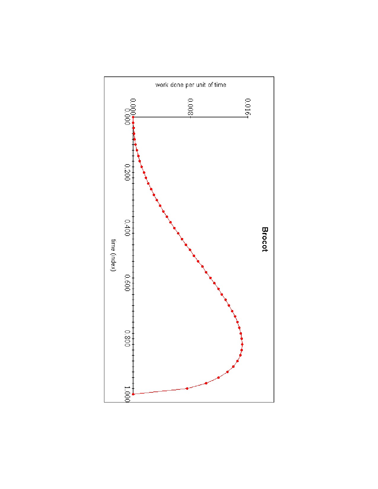
In calculus, the total work done is found by integration, that is, by finding the area
under the curve. I approximated the area by using Simpson's Rule. The Brocot graph
divided the time index into 50 parts, accurate to 2 decimal places. By dividing it into
more parts, I could get a more accurate approximation: dividing it into 10,000 parts, easy
to do on a computer, gave a work done index of 0.3927. If you would like to try this on
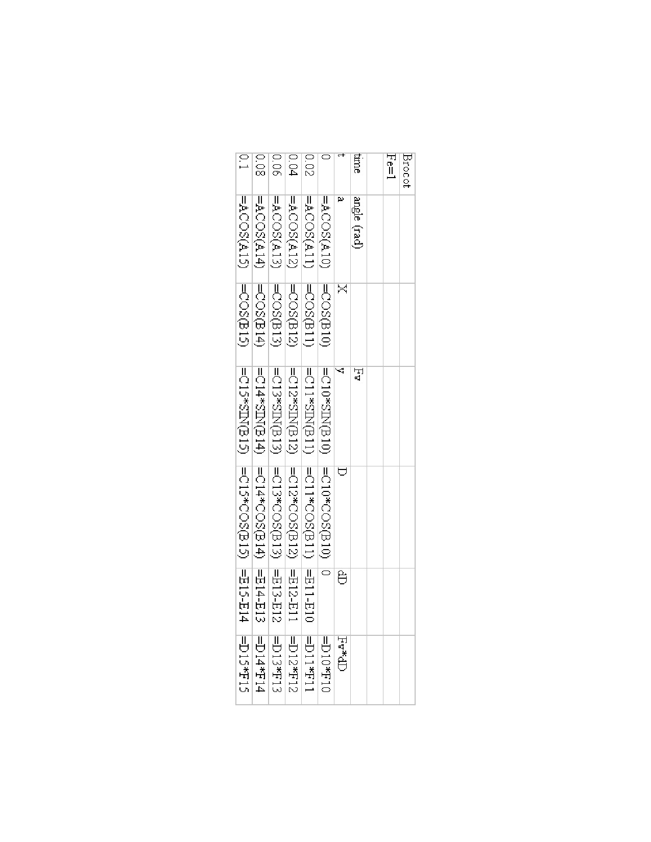
your computer, use the formulas on the page after the Brocot graph.
A practical example would demonstrate the usefulness of this information. A friend
asked me to look at the escapement of a Seth Thomas regulator wall clock with
Graham-style pallets. By inspection, I could see that the design was based on a square, so
the impulse face's angle of the entry pallet should have been horizontal and the impulse
face's angle of the exit pallet should have been vertical. On the exit side, the impulse face
was almost vertical, so I decided to leave it alone. On the entry side, the impulse face was
almost parallel to Fe. I estimated the angle FeFi to be about 70º.
Fi = 1 x cos (70) = 0.342
Fp = 0.342 x cos (20) = 0.321
This does not account for drop, so compare this efficiency of 32% with 50%. The clock
was less efficient by more than a third on the entry side because the impulse face's angle
was incorrect. Since there was plenty of lock, I decided to change the impulse face's
angle by as much as I could without sacrificing all the lock. I did this using an Arkansas
stone, installing the pallet frequently to check the lock. The result was not horizontal, but
an improvement over the previous angle. Then I polished, cleaned and oiled the impulse
face. By decreasing the angle FeFi by about 10º, there was an improvement in efficiency:
Fi
= cos (60) = 0.5
Fp = 0.5 cos (30) = 0.433
Efficiency improved by over 20%. This example demonstrates how this information is
useful to the repairman. While it may not be possible to adjust the impulse face's angle
by as much as would be ideal, an improvement is surely better than none.
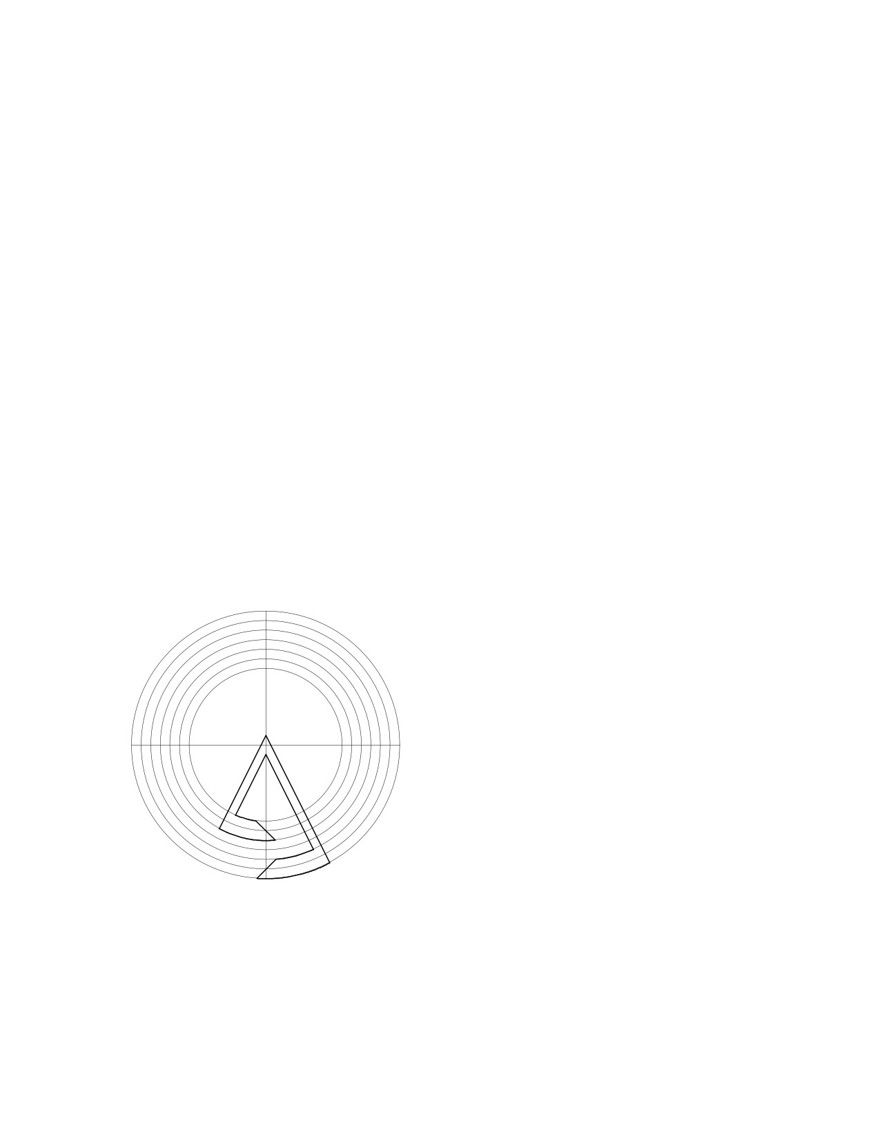
The most difficult part of an escapement
drawing is the calculations for the verge cir-
cle radii, which is critical for the Pin Wheel
escapement. Here there are seven circles (not
drawn to scale). If the 4th circle, between the
pallets, has a radius of 6", the others must be
1
7
calculated from this circle. If the escape
wheel's pin has a diameter of 1/16 of an inch,
or 0.0625", the gap between the two pallets
must be greater than this, say 0.1": the radii
of the 3rd and the 5th circles would be 5.95"
and 6.05" respectively. The gap between the
locking face of the entry pallet and the let-off
corner of the exit pallet must be equal to the
arc between two escape wheel pins (less the diameter of one pin and less the allowance
for drop). If the escape wheel had fifteen pins and a radius of 3", its arc would be:
arc = 3 x (24º x pi) / 180 = 1.26"
(because 24º x 15 = 360º), but you allow 1.5º for drop:
arc = 3 x (22.5 x pi) / 180 = 1.18"
and for the pin diameter: arc = 1.18 - 0.0625 = 1.12" (to two decimal places).
The radius of the 1st circle is therefore:
6 - (1.12 / 2) = 5.44"
35
and the radius of the 7th circle is 6.56".
The radius of the 2nd circle is half way between the 1st and the 3rd:
(5.95 + 5.44) / 2 = 5.70"
and the radius of the 6th circle is half way between the 5th and the 7th:
(6.05 + 6.56) / 2 = 6.30"
The radius of the 4th circle may appear to be arbitrary because it is not determined
by the tooth span between the pallets, as it would be for the Graham, Recoil, and Brocot.
It is determined only by the desired angle of pendulum swing.
Consider a pallet circle that was determined by a tooth span, such as the Graham
escapement with the 15 tooth escape wheel in chapter 10. It had a tooth span of 5.5 teeth,
so the angle between the pallets was: (5.5 / 15) x 360 = 132º, half of which was 66º. The
escape circle radius was 3", so the pallet circle radius could be found by triangulation:
tan (66) = Rp / Re
Rp = Re x tan (66) = 3 tan (66) = 6.74"
Rp = ?
Continuing with the Graham in chapter 10, its escape wheel had
a radius of 3", so the arc between two teeth was:
arc = (3" x 24º x pi) / 180º = 1.26"
90º
The arc per beat (12º): 1.26 / 2 = 0.63"
Allow 1.5º for drop:
arc = (0.63 x 10.5º) / 12º = 0.55"
This is the thickness of the pallets.
66º
Re = 3"
Therefore, the entry pallet locking face has a pallet circle radius of:
6.74 + 0.27 = 7.01"
and the exit pallet locking face has a pallet circle radius of :
6.74 - 0.27 = 6.47".
Replacing the Pallets.
Suppose a British grandfather clock
movement were brought for repair with no
pallets. You determine by inspecting the 30
tooth escape wheel that the clock had a recoil
escapement. The distance between the escape
wheel bushing and the pallet bushing is 1.6".
The escape wheel has a diameter of 2", so the
escape circle's radius is 1". First, draw the pal-
let you want over an ideal Graham pallet and
remove the latter:
36
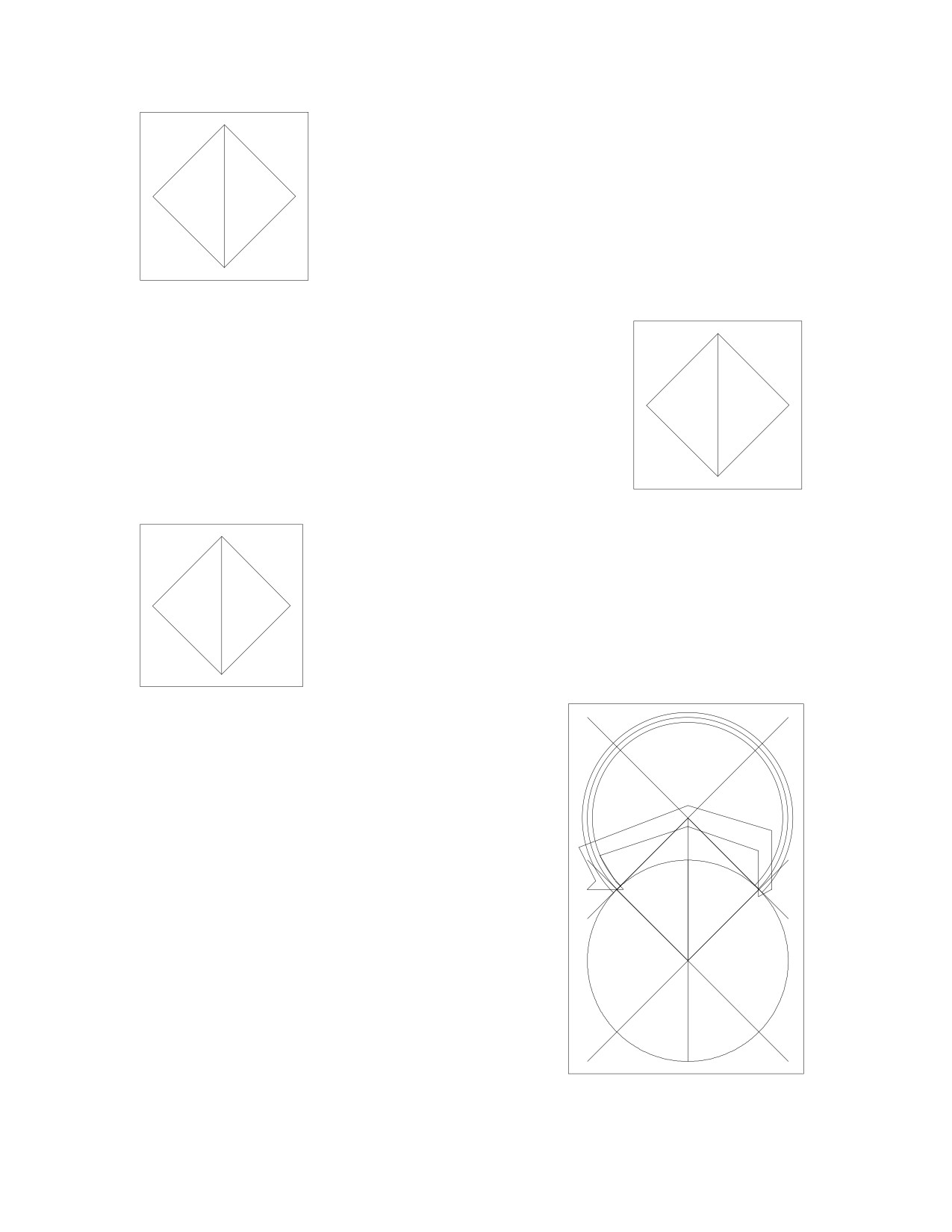
Draw two triangles using this arrangement:
cos (A) = 1 / 1.6
A = acos (1 / 1.6) = 51.3º
1.6
90
Use this to determine the tooth span:
30 x (2 x 51.3 / 360) = 8.553
1
A
so you should use a span of 8.5 teeth.
To recalculate the angle A: (8.5 x 360) / (2 x 30) = A = 51º
1.59
90
1
51
Assume a small error in measurement:
39
39
cos (51) = 1 / h
1.23
1.23
h = 1 / cos (51) = 1.59"
90
1.59
90
The pallet angle is : 180 - 90 - 51 = 39º
The pallet circle radius is:
1
1
Rp = 1 x tan (51) = 1.23
51
51
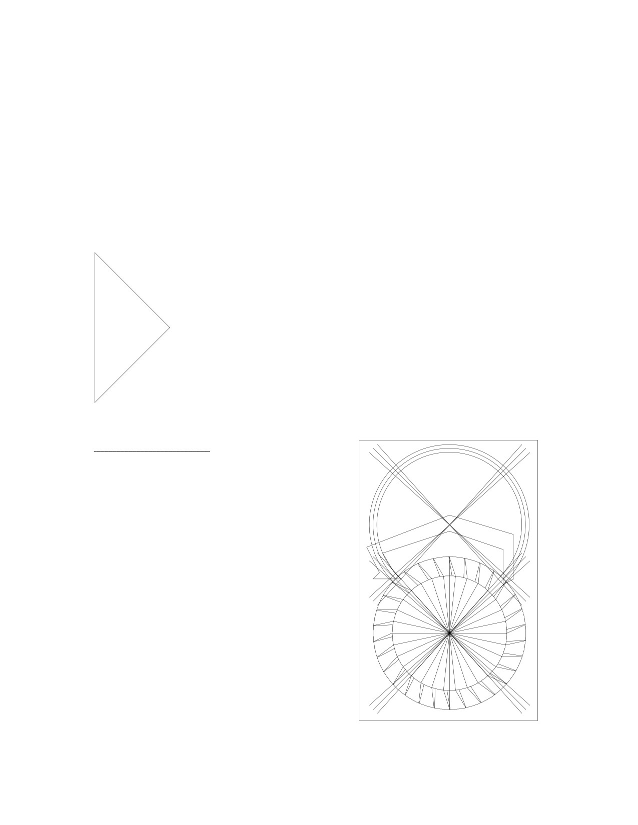
By comparing this drawing with the one on the
previous page, calculate the positions of the tips of
the pallets. The inside tip of the entry pallet needs to
be at a slightly smaller angle from vertical:
Angle = 39 - (3 x (1 / 1.23) = 36.6º
and the radius:
r = 1.23 - ((2 x pi) / (4 x 30)) = 1.18"
39
39
1.23
1.23
Similarly for the exit pallet:
Angle = 36.6º.
90
90
1.59
r = 1.23 + ((2 x pi) / (4 x 30)) = 1.28"
The rest of the pallet could be drawn any way
1
1
51
51
you wish. To explain the numbers above, the escape
wheel has an angle of 12º between two teeth. A tooth
will travel 6º per beat. The pallet angle lines were di-
vided into 3º on either side. Since the pallet radius is
1.23 and the escape radius is 1", multiply the escape
angle of 3º by the ratio of the radii. Since the pallet
radius is larger, the pallet arc is smaller than the es-
cape wheel arc (which has an angle of 3º).
37
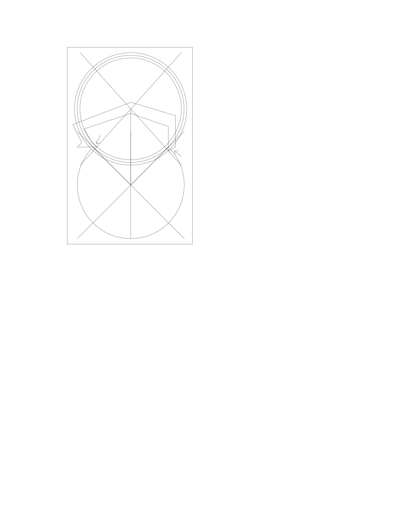
For the radius calculation, decrease the
pallet radius on the entry pallet by the
amount of a quarter of the arc between two
escape wheel teeth, and increase the pallet
radius on the exit pallet similarly. This is
only a close approximation because the
change in the pallet circle's radius is as-
sumed to be equal to the arc of the escape
36.6
36.6
1.18
1.28
circle, but an arc is not a straight line.
Once the pallet blank is made, it must
be fitted because there is no drop. By filing
1.59
on the surfaces pointed to by the arrows,
some inside and outside drop could be cre-
ated.
When designing a Graham pallet, the issue becomes more complicated because of
lock. I would suggest that the best way to design the pallets would be to make the blank
with impulse faces that have angles relative to Fe smaller than 45º, such as 25º. When
fitting the pallets to the clock, file first on the inside and outside surfaces to create
enough inside and outside drop. Then file on the impulse face to increase the impulse
angle until the lock has been reduced to about 1º. To be practical in a manufacturing
situation, the measurement deviations must be accounted for to keep rejects statistically
below 5%. The need to account for these deviations means that a compromise situation
arises because fitting each verge by hand would interfere with mass production and
economies of scale.
Fitting a Brocot pallet requires the calculation of the pallet circle's radius. If the
escape wheel rotates 6º per beat, and its radius were 1", the arc would be:
arc = (1 x 6 x pi) / 180 = 0.105"
I suggest 1.5º of drop, so the radius of the pallet's circle should be:
r = (1 x 4.5 x pi) / 180 = 0.08"
Using the recoil example, the Brocot pallet should be positioned such that the point
where the pallet releases the escape tooth should have a pallet circle radius of 1.18" and
an angle of 36.6º from vertical for the entry pallet, and a radius of 1.28" and an angle of
36.6º for the exit pallet. Then the lock and drop could be further adjusted by raising or
lowering the pallets, or by changing the gap between the pallets.
By studying the above example, you could see how you could use one type of
escapement for the calculations, and then apply them to the type of escapement you want
to create. A step-by-step process makes the calculations easier.
38
Watch
Escapements
39
(blank page)
40
Introduction:
Drawing watch escapements requires much more detail than drawing the Graham
(clock) escapement. I will pay most attention to the modern Swiss watch with the
club-tooth escape wheel as it is the most commonly encountered at the bench.
Watch and clock escapements are similar in that they should have symmetrical de-
signs, so that the impulses the pallets receive would be equal. The efficiency of the
escapement should be the same for both pallets. The impulse face of each pallet should
have an angle of 45º relative to the direction of the force that the escape tooth applies to
the pallet during impulse if the angle between this force and the force that acts to rotate
the pallet were 90º. If the pallet's impulse face angle were not correct, there would be a
considerable loss of efficiency, or the ability of the balance wheel to receive impulses from
the escape wheel. This is covered in detail in Chapter 4 of the Clock Escapement section.
The most significant difference between clock and watch escapements, such as the
Graham escapement and the Swiss Lever, is that the clock's pendulum is not independent
of the pallets, whereas the watch's balance wheel is independent of the pallets most of the
time. This means that the clock escapement should have pallets with curved locking faces
to achieve a dead-beat, so that there would be no recoil as the escape tooth slides along
the pallet locking face. The watch escapement, however, should have pallets with locking
faces that allow the escape tooth to move forwards slightly as it slides up the pallet's
locking face, so as to create draw. The draw is a small binding action that helps to keep
the pallet fork over to the side, against the banking pin, until the balance wheel's roller
jewel returns, so that the fork's guard pin would not rub against the balance wheel's roller
table and thereby interfere with the freedom of rotation of the balance wheel. Since
watches require draw, the equidistant lock of the pallets is desirable in order to have equal
draw for both pallets. This is covered in detail in Chapter 9 of the Clock Escapement
section.
If you are a watchmaker with no interest in clocks, I would recommend that you
consider reading the chapters concerning clock escapements because the logic behind the
drawings is the same, and it is easier to introduce a reader to the drawing techniques with
less difficult examples, (in other words, examples of simpler escapements that apply to
clocks). It would be necessary to understand the basic principles behind escapement
drawings before attempting to draw complicated watch escapements that would work in a
simulation on a computer.
12: Drawing a Club-Tooth Escape Wheel.
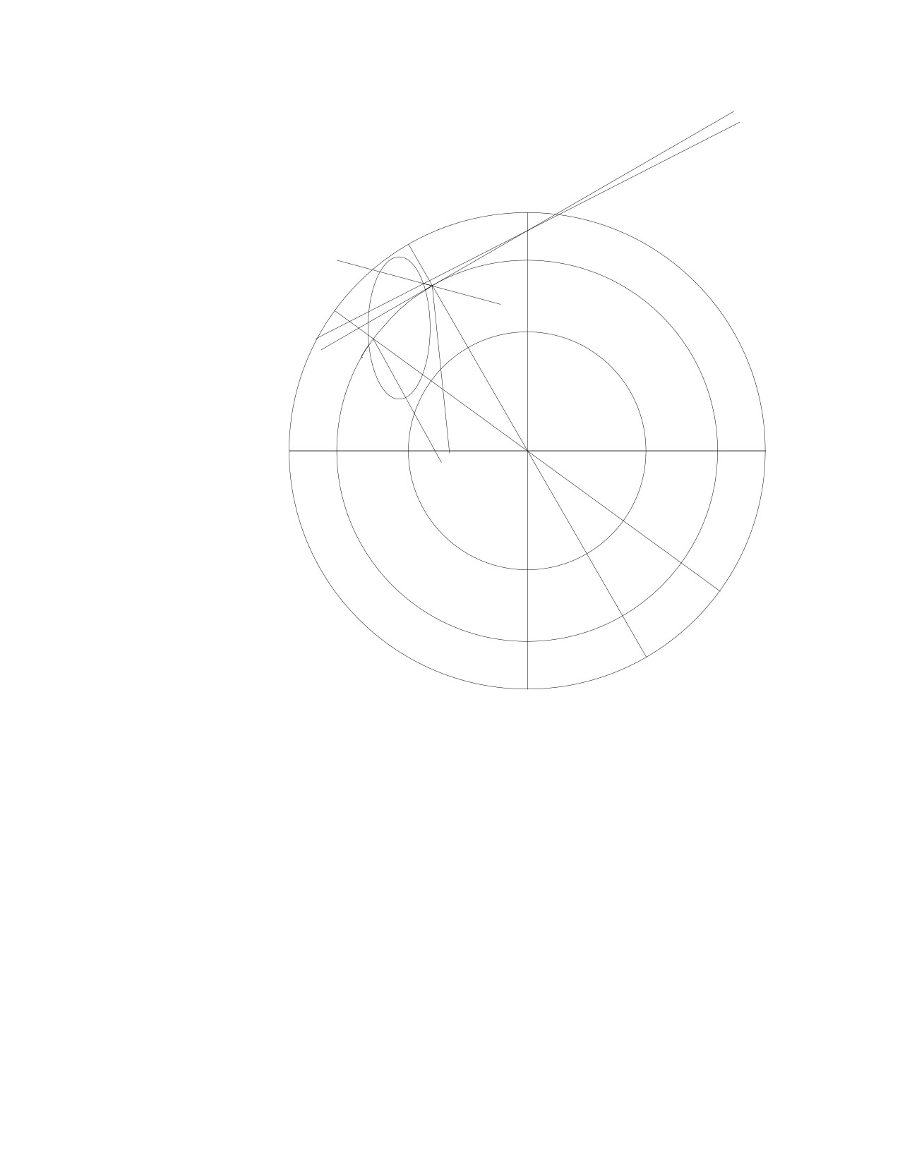
While reading this chapter, please refer to the drawing in figure 1 on the next page.
First, draw three circles with diameters of 4 and 6 and 7.5 inches. Center them on the page
and draw a horizontal and a vertical line across the largest circle. Take the vertical line (1)
and rotate it counterclockwise by 30º to get line (2): this will be the escape circle's radius
for the first tooth. Rotate line (2) counterclockwise by 45º to get line (3): this will be the
impulse face of the escape tooth. I have shortened line (3) and several other lines only in
order to make this drawing easier to understand. Place line (3) onto the point where line
(2) intersects the six inch circle. Then rotate line (3) counterclockwise by another 45º to
get line (4): this line will become the pallet circle's radius. Place line (4) on the edge of the
six inch circle at the point where the circle intersects with lines (2) and (3). At the point
41
3º
where the vertical
(Fig. 1)
line
(1) intersects
(4)
with line (4), rotate
(5)
line
(4) clockwise
by 3º: this will de-
termine the amount
of lock that this
design will have.
While the ideal
45º
45º
amount of lock is
(3)
recommended to
24º
be only 1º, I rec-
(2)
(1)
ommend 3º in this
24º
drawing because it
(6)
24º
30º
will make the lock
(7)
easier to see during
4"
6"
7.5"
the simulation. It
diameter
(8)
will also make the
simulation
more
forgiving if errors
were made during
the preparation of
the drawing. The
best way to ensure
that line (4) is ro-
tated about the
point where it in-
tersects line
(1) is
to center line
(4)
on the page shown on your computer screen before rotating, since line (1) has already
been centered on the page.
Rotate line (2) clockwise by 24º to get line (6), and place it onto the point where lines
(2), (3), and (4) intersect. Line (6) will be the tooth's locking face, and the point where it
intersects the other three lines will be the entrance corner of the tooth.
Rotate line (2) counterclockwise by 24º, since there are 24º between each tooth of a
15 tooth escape wheel, to get line (7). Rotate line (7) clockwise by 24º to get line (8).
Place line (8) onto the point where line (7) intersects the six inch circle. Line (8) will be
the locking face of the next tooth. The locking faces of the teeth will appear to lean
forwards by 24º.
Draw a three inch circle and place in onto the point where lines (3) and (5) intersect.
This circle can be made larger or smaller, or stretched at will until the desired shape is
achieved to trace the curve of the tooth. I recommend that you draw a relatively thin tooth
that would allow the pallet to clear during the simulation. After the simulation, when you
know how much clearance you have, you could draw the escape wheel again.
42
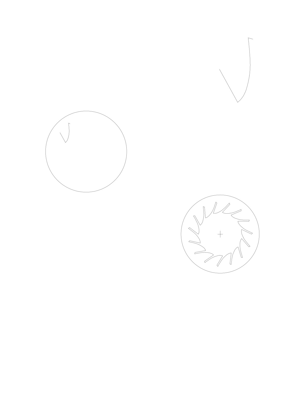
Draw the first tooth over lines (3) and (8), and trace the
curve over the ellipse, so that you get a tooth that looks like this:
Move all the lines and the two inner circles to
one side, so that all you have on the page is the
7.5 inch circle and the tooth in the same position.
Group the tooth and the circle, and rotate the
group by 24º in whichever direction you choose.
Duplicate the group and rotate again. Duplicate the
group again and rotate again. Repeat this until you
have 15 groups, all in the same place. Then ungroup
all 15 groups, so that you end up with 15 teeth and
15 circles. Delete 14 of the circles, one by one, until
you have the complete wheel.
In order for the escape wheel to be true
(or
perfectly centered), it is necessary to rotate the tooth
inside a circle that extends beyond the tooth. Since
the tooth extends slightly beyond the edge of the six
inch circle, a larger circle is needed for the drawing.
43
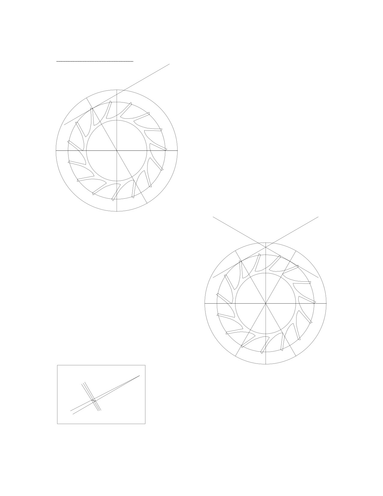
13: Drawing the Pallets.
(4)
90º
The first tooth was drawn next to line
(1)
(2), which had an angle of 30º relative to
(2)
30º
the vertical line
(1). The
30º angle was
chosen so that there would be a 2.5 tooth
span between the pallets for a
15 tooth
wheel. The angle between lines (2) and (4)
was 90º so that the angle between the force
exerted by the escape tooth and the force
that acted to rotate the pallet would be 90º.
(10)
(4)
pallet circle
center
90º
90º
(1)
Rotate line (1) clockwise by 30º to get
(2)
(9)
line (9). Rotate line (9) by 90º to get line
30º
30º
(10). Place line (10) onto the point where
line (9) intersects the edge of the six inch
circle. The point where lines (1), (4) and
(10) intersect will be the pallet's circle
center.
1º
If you rotate line (2) counterclockwise by 2º, you
1º
would see that the escape wheel's impulse face occupies
a span of 2º of escape wheel rotation. (The impulse
face also provides 3º of lift and lock.)
3º
44
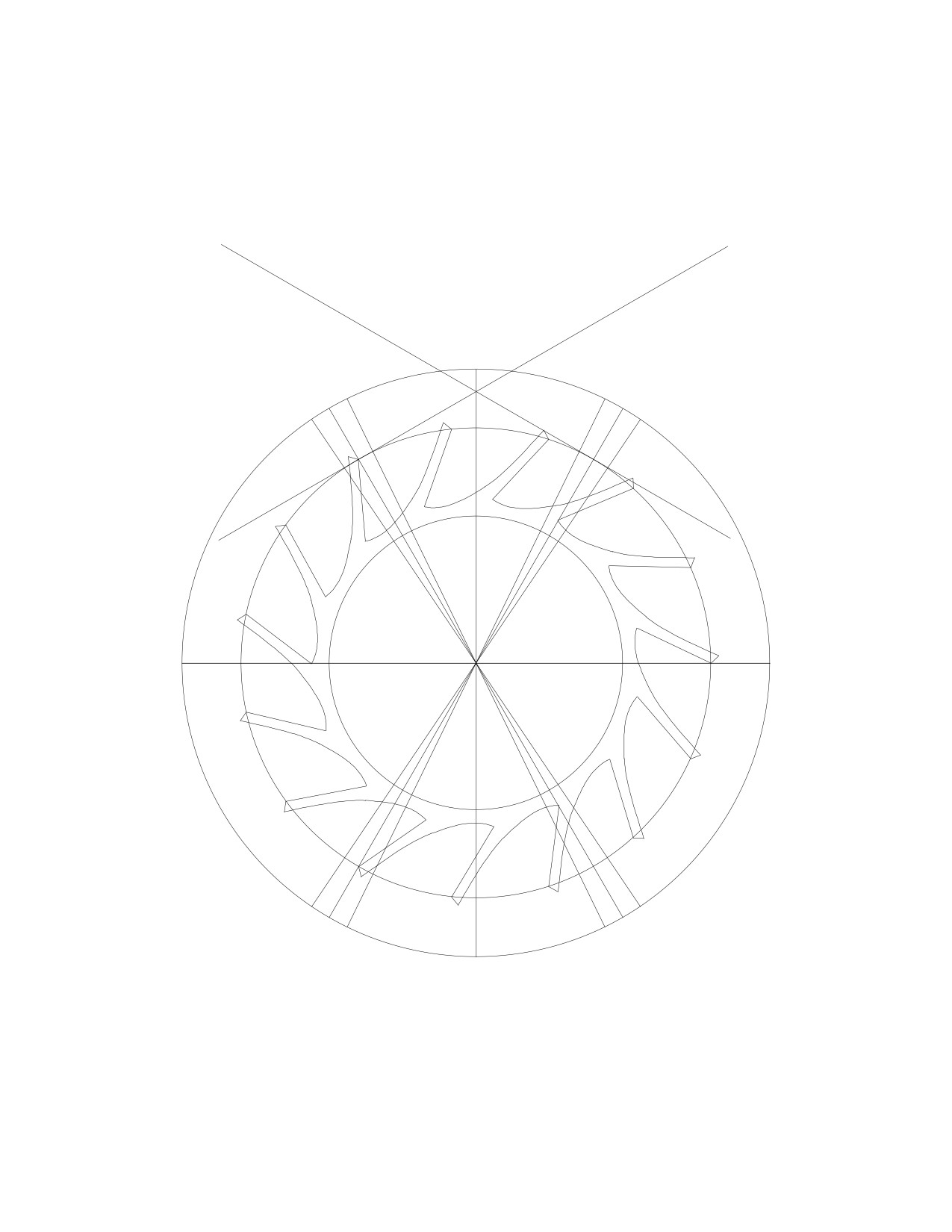
Since the escape wheel rotates by 12º per beat and you want 2º for drop and 2º for
the escape tooth's impulse face, the pallet should occupy a span of 8º. Rotate line (9)
counterclockwise by 4º to get line (11). Rotate line (9) clockwise by 4º to get line (12).
Repeat with line (2) to get lines (13) and (14):
(10)
(4)
4º
4º
4º
4º
(2)
(9)
(14)
(11)
(13)
(12)
45
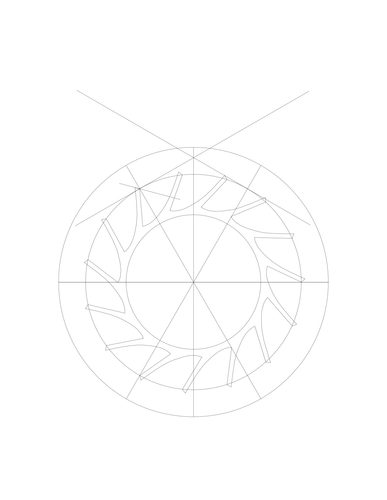
Rotate line (2) counterclockwise by 45º to get line (15). Notice that it is at an angle
half way between the escape circle's radius and the pallet circle's radius, shown by lines (2)
and (4) respectively:
(10)
(4)
(15)
45º
45º
(2)
(9)
30º
30º
46
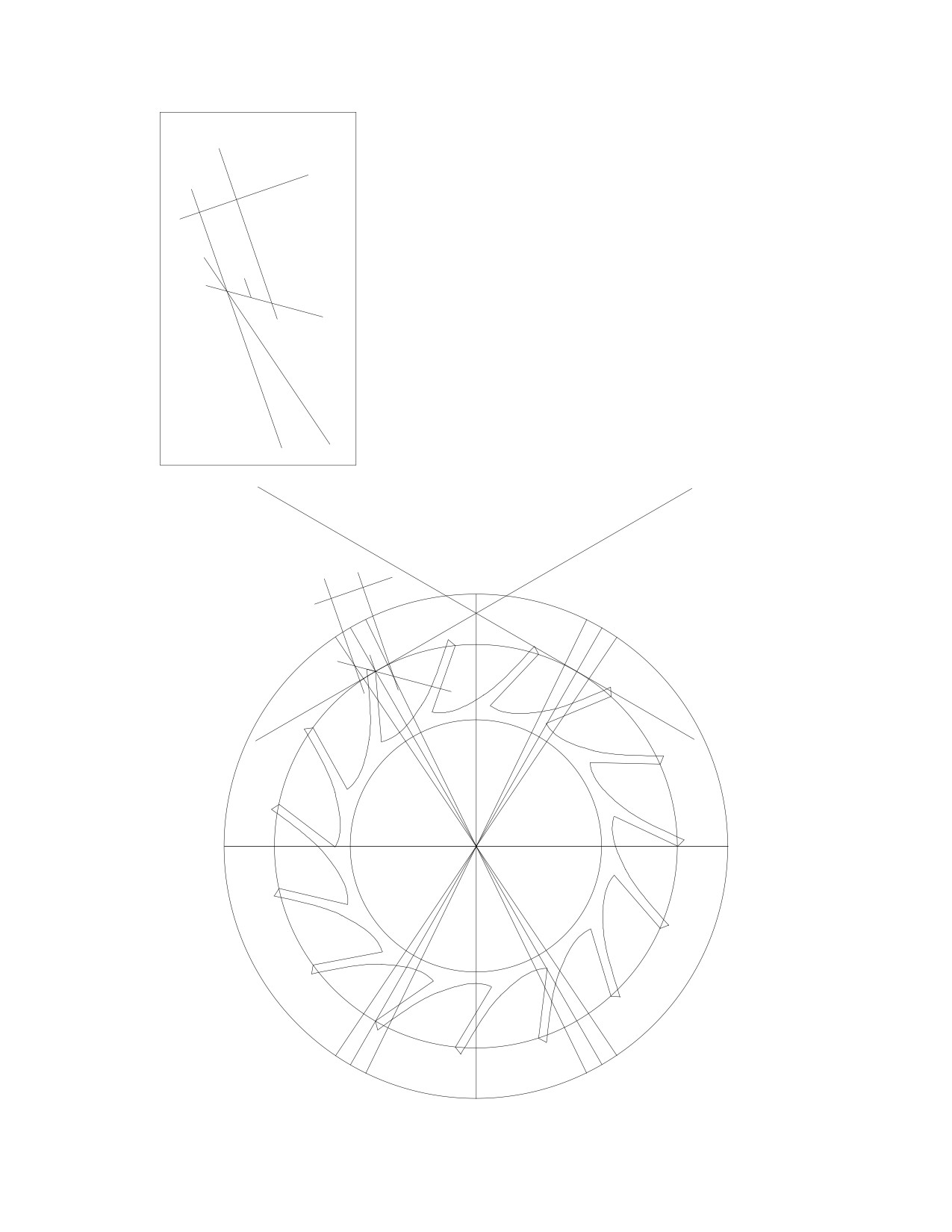
Rotate line (13) clockwise by 15º to get line (16),
(17)
and place it onto the point where lines (13) and (15)
(18)
intersect. Line (16) will be the pallet's locking face, and
90º
it will have a draw angle of 15º. Duplicate line (16) and
place it onto the point where lines
(14) and
(15)
intersect: lines (16) and (17) are parallel. Rotate line
(17) by 90º to get line (18) and place it in a suitable
position along lines (16) and (17). The pallet is now
(15)
recognizable. You could place a small line at the point
where lines (2) and (15) intersect: this small line would
show the mid-point of the pallet.
15º
(16)
(13)
(10)
(4)
(16)
(17)
(18)
(15)
(2)
(9)
(14)
(11)
(13)
(12)
47
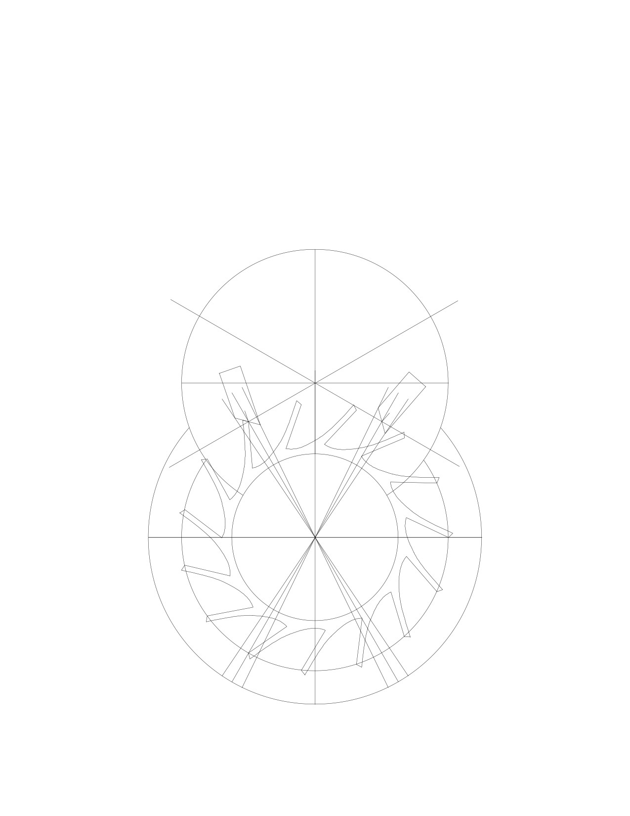
Once you finish the entry pallet, group the lines and duplicate them. Rotate the sec-
ond pallet clockwise by 60º because that is the angle between lines (2) and (9), and then
place the pallet on the exit side such that the mid-point of the impulse face lies on the
point where lines (9) and (10) intersect. Most watches have different pallets, but an es-
capement using the same pallet on both sides can be designed, and using the same pallets
makes manufacture easier.
It will be necessary to draw the pallet circle to perform a simulation. The circle must
be larger than the drawing of the pallets, so I chose a six inch diameter circle, placed a
horizontal and a vertical line in it, grouped the circle and the lines, and then placed them
such that the circle center would lie on the point where lines (1), (4) and (10) intersect.
(10)
(4)
(1)
(2)
(9)
(14)
(11)
(13)
(12)
48
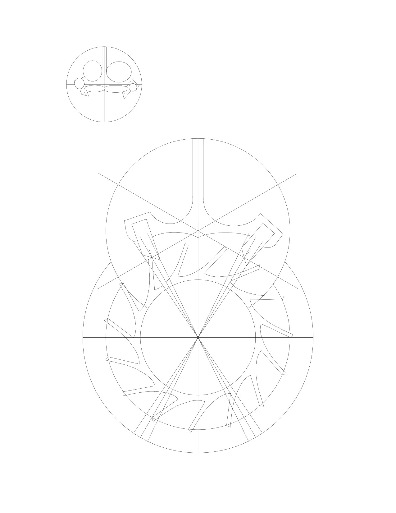
To draw the pallet arms, you could use circles,
stretched and shaped to give the outline you desire. It
should be obvious by looking at the drawing below that
the design is of equidistant impulse.
(10)
(4)
(2)
(9)
(14)
(11)
(13)
(12)
49
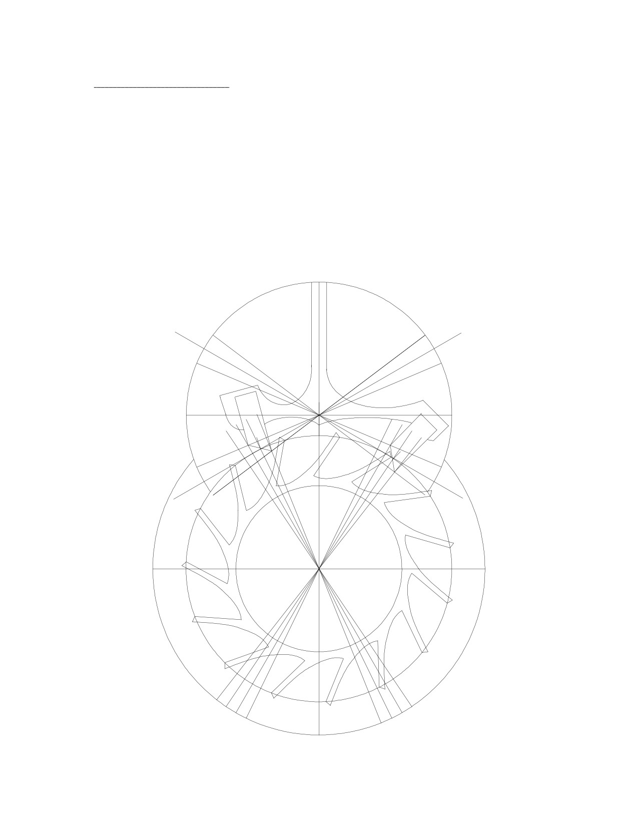
14: Changing the Design.
A different approach is required to create different designs, such as the equidistant
lock drawing below. Rotate lines (14) and (12) clockwise by 4º to get lines (15) and (16)
respectively. Rotate lines (10) and (4) clockwise by 7º to get lines (18) and (20), and
counterclockwise to get lines (17) and (19). Draw the entry pallet's impulse face from the
point where lines (2) and (20) intersect to the point where lines (15) and (19) intersect.
Draw the exit pallet's impulse face from the point where lines (9) and (17) intersect to the
point where lines (16) and (18) intersect. Rotate lines (2) and (9) clockwise by 15º to
draw the locking faces of the pallets. In order to maintain the action of the pallets as sym-
metrical as possible (and to keep the impulse face's angle as close to 45º as possible), the
lift is reduced slightly to 14º and the impulse angles are no longer at 45º, which reduces
efficiency, but the lock and drop are the same on both sides and the pallets are not "out of
angle." The pallets are no longer identical.
7º
7º
(18)
(19)
7º
7º
(10)
(4)
(17)
(20)
(13)
(16)
(2)
(12)
(14)
(9)
(15)
(11)
4º
4º
4º
4º
4º
4º
50
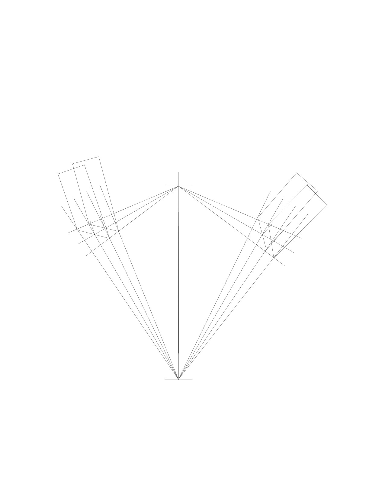
Drawings could be superimposed for comparison, such as this comparison between
the equidistant impulse and lock designs. It reveals that, in the equidistant impulse design,
the exit pallet's impulse face does not exactly fit between the lines: while the exit pallet is
identical to the entry pallet, it is not a mirror image of the entry pallet. The entry pallet
does not have a perfect fit either, but the difference is very small and inconsequential. The
result of the unequal fit on both sides is that the exit pallet releases the escape tooth a little
prematurely, causing the design to be out of angle: the angle on the left side to the
drop-lock position is one degree greater than on the right side. This problem is corrected
in Chapter 22.
L
I
I
L
entry
exit
side
side
51
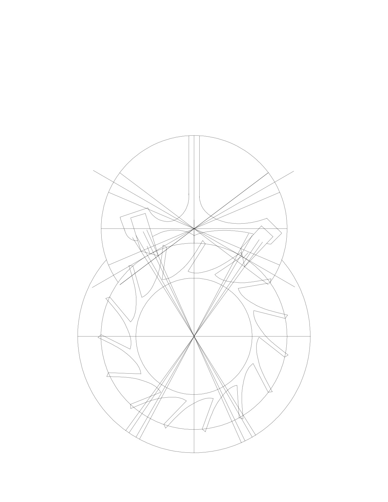
To combine the advantages of equidistant impulse and equidistant lock, watchmakers
have designed an escapement half way between the two, called the semi-tangental es-
capement. Here, the angle between lines (2) and (23) and between lines (9) and (21) is 2º,
so rotate lines (2) and (9) counterclockwise by 2º to get lines (23) and (21). Rotate lines
(12) and (14) clockwise by 2º to get lines (22) and (24). Draw the entry pallet's impulse
face from the point where lines (23) and (20) intersect to the point where lines (24) and
(19) intersect. Draw the exit pallet's impulse face from the point where lines (21) and (17)
intersect to the point where lines (22) and (18) intersect. Rotate lines (23) and (21)
clockwise by 15º to draw the locking faces of the pallets.
7º
7º
(18)
(19)
7º
7º
(10)
(4)
(17)
(20)
(23)
(22)
(2)
(12)
(14)
(9)
(24)
(21)
2º
2º
4º
2º
2º
4º
52
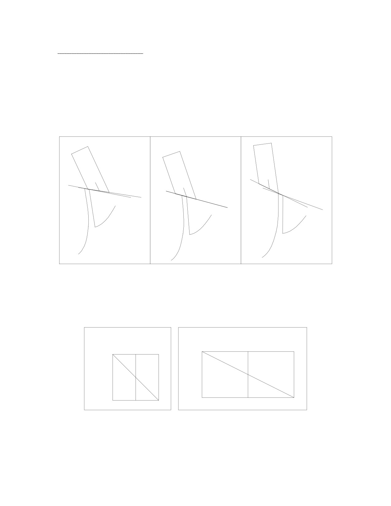
15: Improving the Design.
In order to maximize efficiency, the impulse face of each pallet should have an angle
half way between its corresponding escape circle radius line and pallet circle radius line.
Looking at the design with equidistant impulse, if the angle between lines (2) and (4) were
90º, then the impulse face's angle should be 45º and line (15) is half way between lines (2)
and (4). A change in design is needed in practice because the escape wheel's teeth are too
narrow and therefore too fragile. Thus far, I have assumed that the escape tooth's impulse
face should be parallel to the pallet's impulse face in the drawing. However, the simulation
reveals, as suspected, that the lines do not remain parallel during impulse:
This means that they need not be parallel in the design. If the pallet's impulse face re-
mained unchanged, the efficiency of the escapement would remain unchanged, and we
could change the shape of the escape tooth without sacrificing efficiency. The span of the
tooth's impulse face could be increased from 2º to 4º so as to draw a wider tooth. The
amount of lock would remain unchanged at 3º for the purpose of the drawing:
2º
2º
1º
1º
3º
3º
34º
45º
If the escape tooth occupied a span of 4º and there were 2º of drop, the pallet would
occupy a span of 6º, for a total span of 12º per beat. New pallets must be drawn.
53
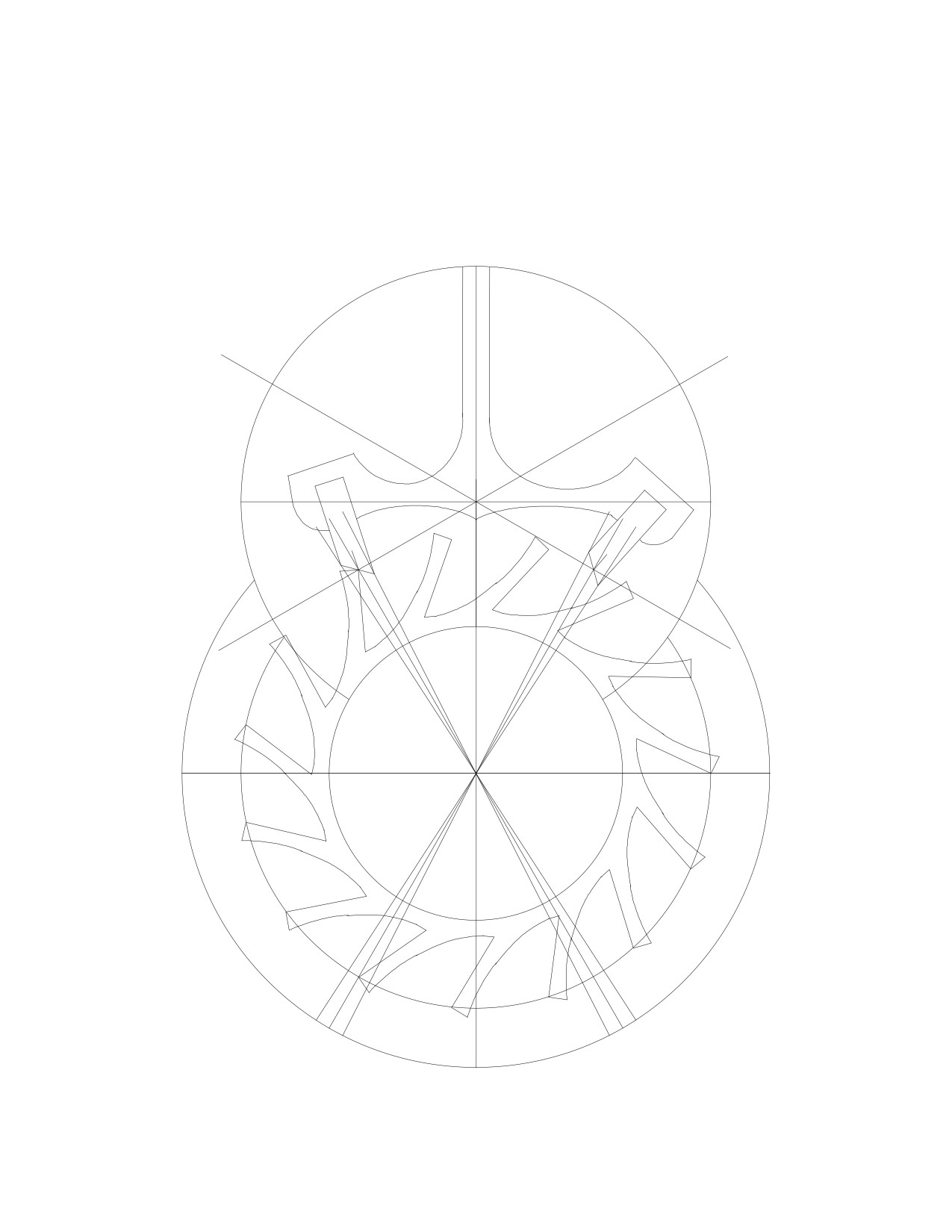
Rotate line (9) counterclockwise by 3º to get line (25), and clockwise by 3º to get line
(26). Rotate line (2) counterclockwise by 3º to get line (27), and clockwise by 3º to get
line (28). Rotate line (27) clockwise by 15º and draw the locking face. Draw the rest of
the pallet as before, then duplicate it and rotate it clockwise by 60º, placing it on the exit
side. The pallets are narrower, but the teeth are wider. Notice the difference in the angles
of the pallet and escape tooth impulse faces.
(10)
(4)
(2)
(9)
(28)
(25)
(27)
(26)
54
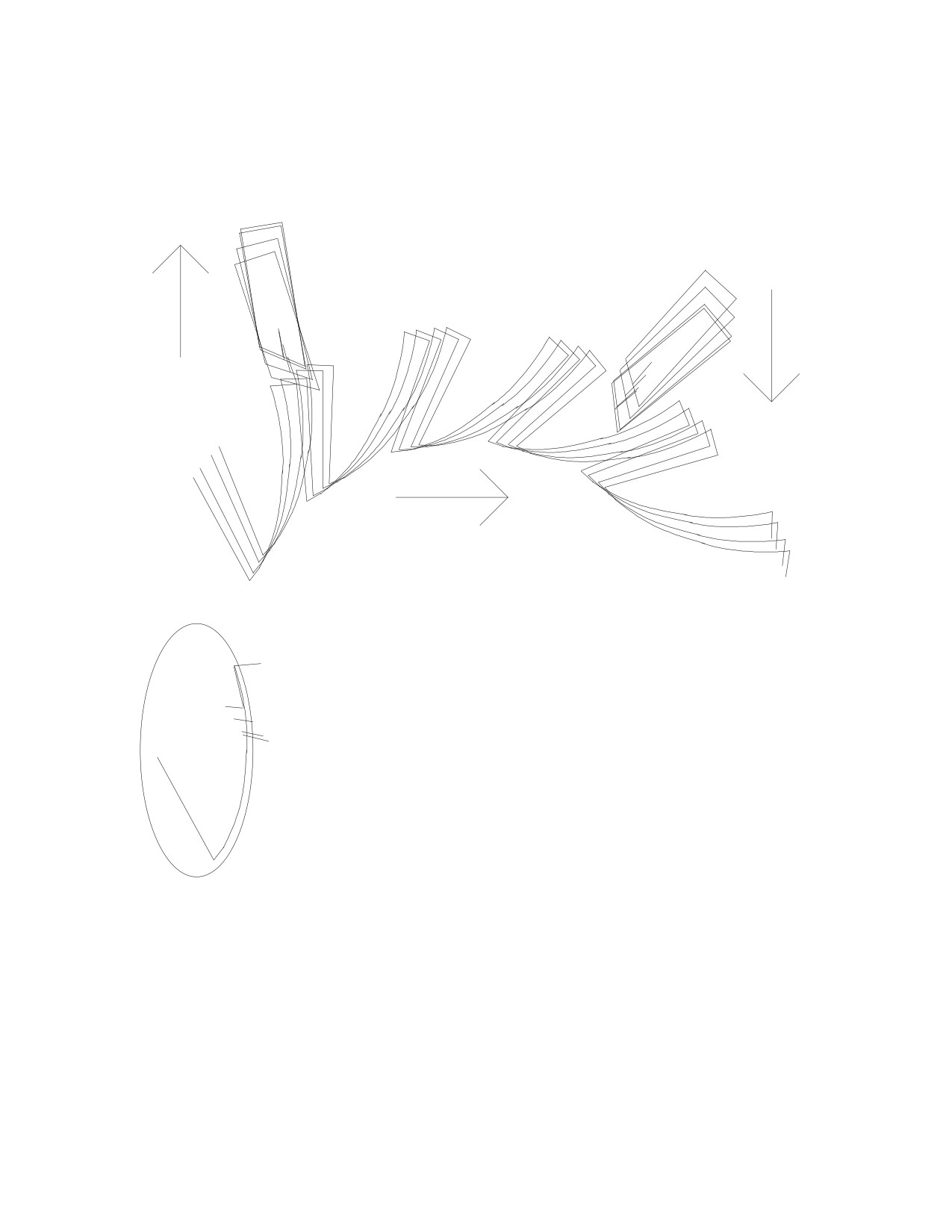
Another way to make a stronger tooth would be to trace the path of the pallet during
the simulation, and then to draw the curve on the back side of the tooth again. If the
simulation were superimposed for the action of the escapement as the tooth pushed on the
entry pallet,
the exit pallet enters the space between two teeth. The distance
between the exit pallet and the tooth that just passed it could be
measured by drawing lines from the pallet to the tooth. These lines
could be used as a guide when drawing a new curve. Move the ellipse
to other positions and change its shape until you trace a path for a
new curve more like the path of the pallet. If you draw the lines on the
tooth next to the exit pallet and are drawing the new tooth next to the
entry pallet, you must rotate the lines by 24º for every tooth in
between, that is, by 72º counterclockwise. I drew a new escape wheel
using the same principles as in the first drawing plus these lines as a
guide. Unfortunately, the path of the pallet would be very difficult to
predict before doing a simulation.
It is preferable to draw the first escape wheel with narrow teeth because it would be
much more likely to work in a simulation. For the same reason, I recommend designing
the first drawing with no less than 2º of lock and 2º of drop. The simulation would show
the lock and drop more clearly and it would be more forgiving if errors were made. In
addition, the simulation would be much more likely to work when changes in design are
made, such as when going from equidistant impulse to equidistant lock. Once you have
some practice, then try a design with the theoretically correct 1º of lock and 1º of drop.
You would find that any error made in the drawing would result in binding or recoil.
55
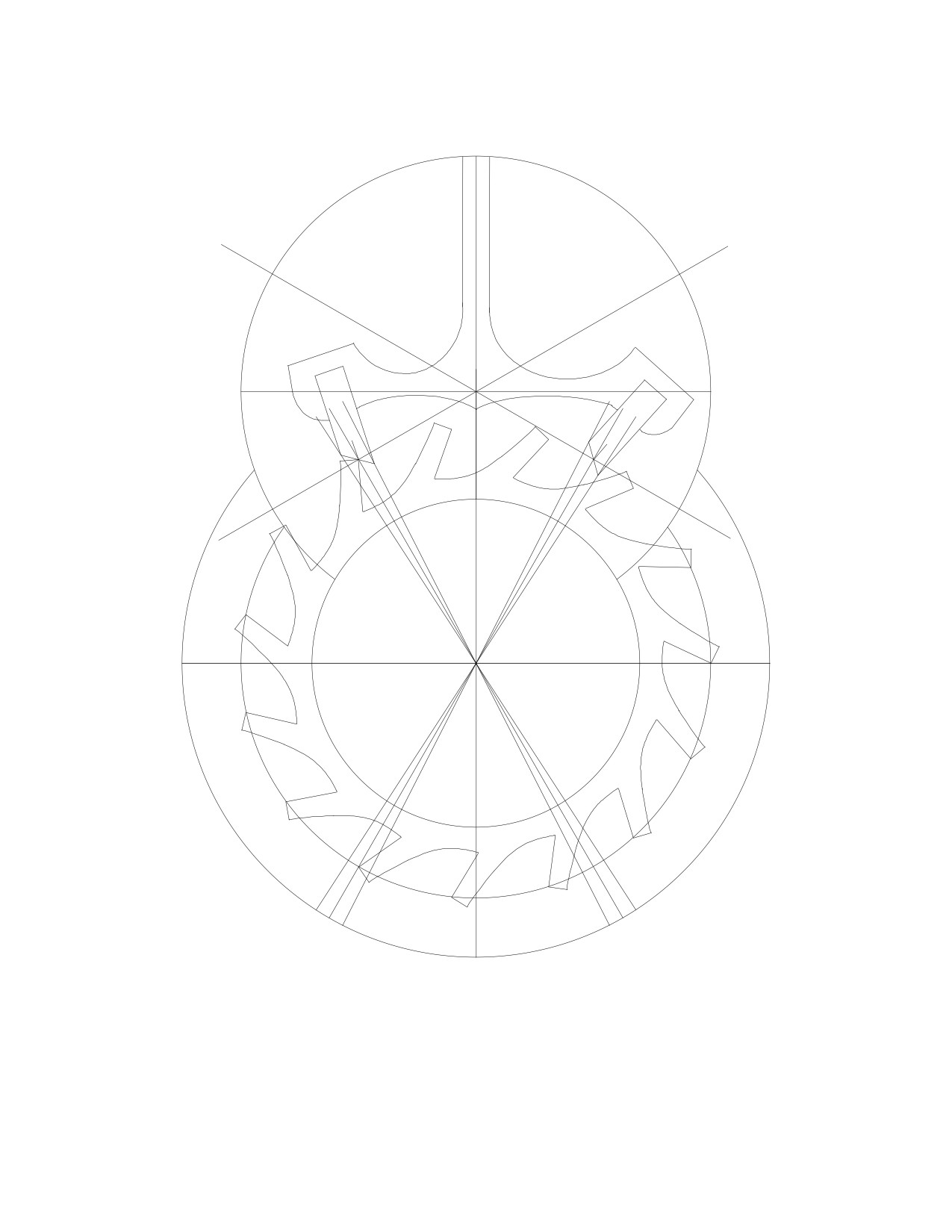
This drawing has the same, smaller pallets and a new escape wheel:
(10)
(4)
(2)
(9)
(28)
(25)
(27)
(26)
This drawing does not include the pallet fork and the roller table, primarily because of
the math involved. These are added in Chapter 22.
56
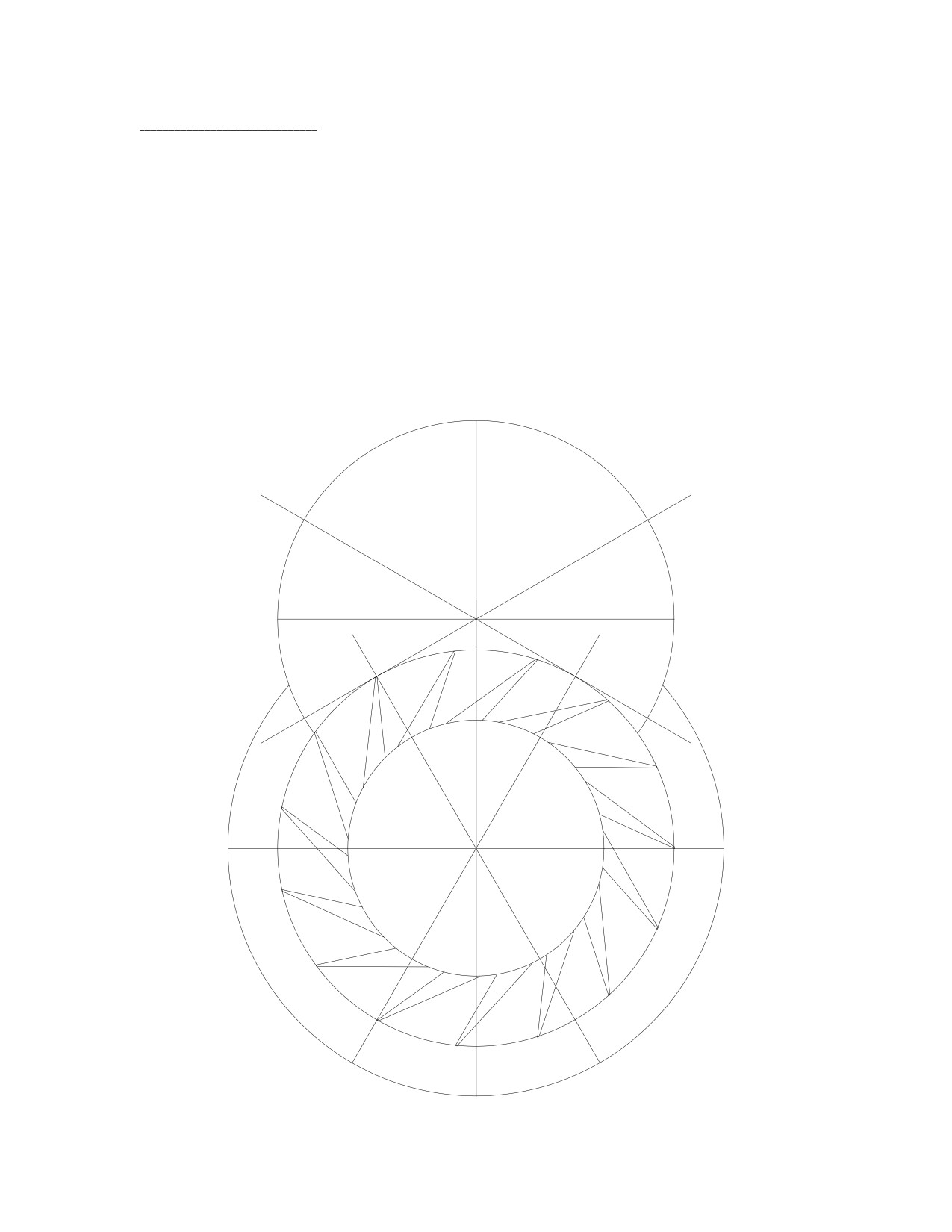
16:The English Lever.
This escapement has several disadvantages. The escape wheel's teeth are pointed, so
they lack the strength of the club-tooth design. The escape wheel's teeth do not have
impulse faces of their own, so the lock must be created by changing the design of the
pallets. This results in the pallets having impulse faces with angles other than the optimal
angle, so the design is less efficient.
The escape tooth is simple. The locking face appears to lean forwards by 24º. There
is an angle of 12º between the front and the back of the tooth, and there is a small gap to
create some thickness.
As in the Swiss Lever, there is 30º between the vertical line (1) and the escape circle
radius lines, (2) and (3), which are used to design the pallets. Rotate line (2) by 90º to get
line (4). Rotate line (3) by 90º to get line (5). Place the pallet circle such that its center lies
on the point where lines (4) and (5) intersect.
(5)
(4)
pallet
circle center
90º
90º
(1)
(2)
(3)
30º
30º
57
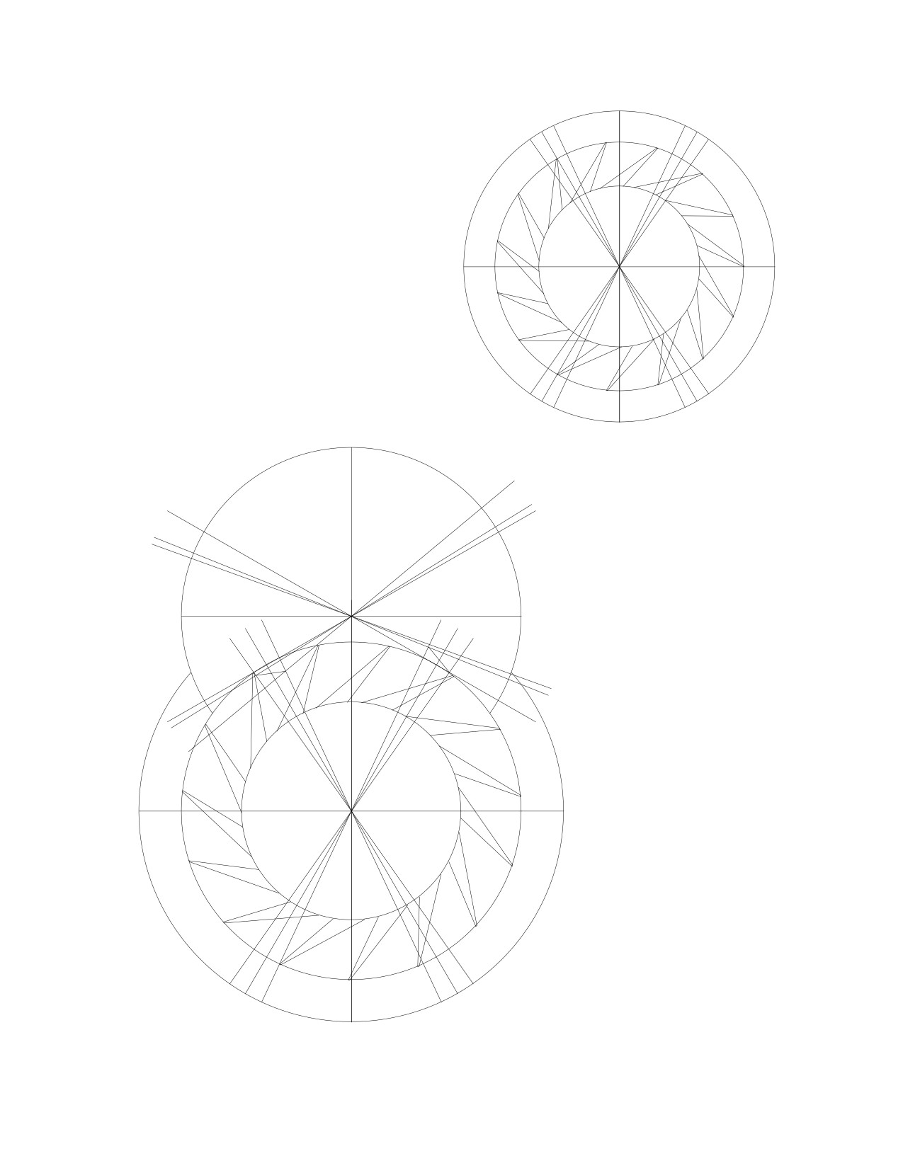
5º
5º5º
5º
The 15 tooth escape wheel rotates by
12º per beat, so make the pallet occupy a
span of 10º, in order to allow 2º for drop.
To draw the impulse
face lines, it is necessary
to determine their posi-
8º
2º
tions. Rotate line (4) by
8º
2º
(for lock) counter-
2º
clockwise to get line
(10). Then rotate line
(10) by
8º counter-
clockwise
to get line
(11). Rotate line (5) by
8º counterclockwise to
(13)
get line (12), and by 2º
(4)
(12)
more to get line
(13).
(1)
Draw a line from the
(2)
(3)
(7)
(8)
(5)
(10)
(6)
(9)
point where lines (6) and
(11)
(10) intersect to where
lines (7) and (11) inter-
sect: this will be the entry
pallet's
impulse face.
Draw a second line from
the point where lines (8)
and
(12) intersect to
where lines (5) and (9)
intersect: this will be the
exit pallet's impulse face.
58
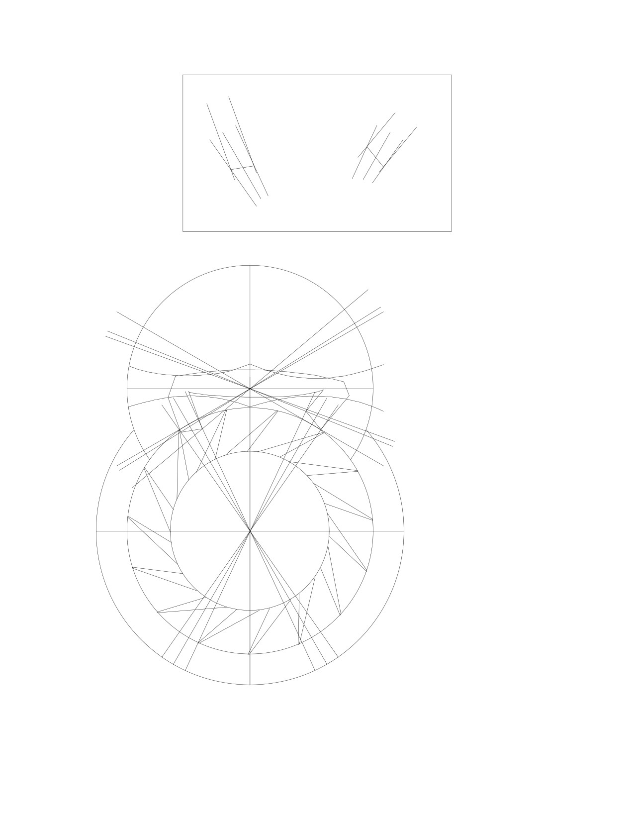
(15)
(14)
(16)
15º
(17)
15º
(8)
(9)
(7)
(3)
(6)
(2)
8º
2º
8º
2º
Rotate line
(6)
clockwise by 15º to get
line (14), which will be
the entry pallet's lock-
ing face with a draw
angle of 15º. Duplicate
line (14) and place it on
(13)
the point where lines
(4)
(12)
(1)
(7) and
(11) intersect.
(2)
(3)
(7)
(8)
(5)
Repeat this procedure
(10)
(6)
(9)
for the exit pallet: ro-
(11)
tate line
(8) clockwise
by 15º to get line (16).
Duplicate line (16) and
place it on the point
where lines (5) and (9)
intersect. Finish the
drawing as you wish.
59
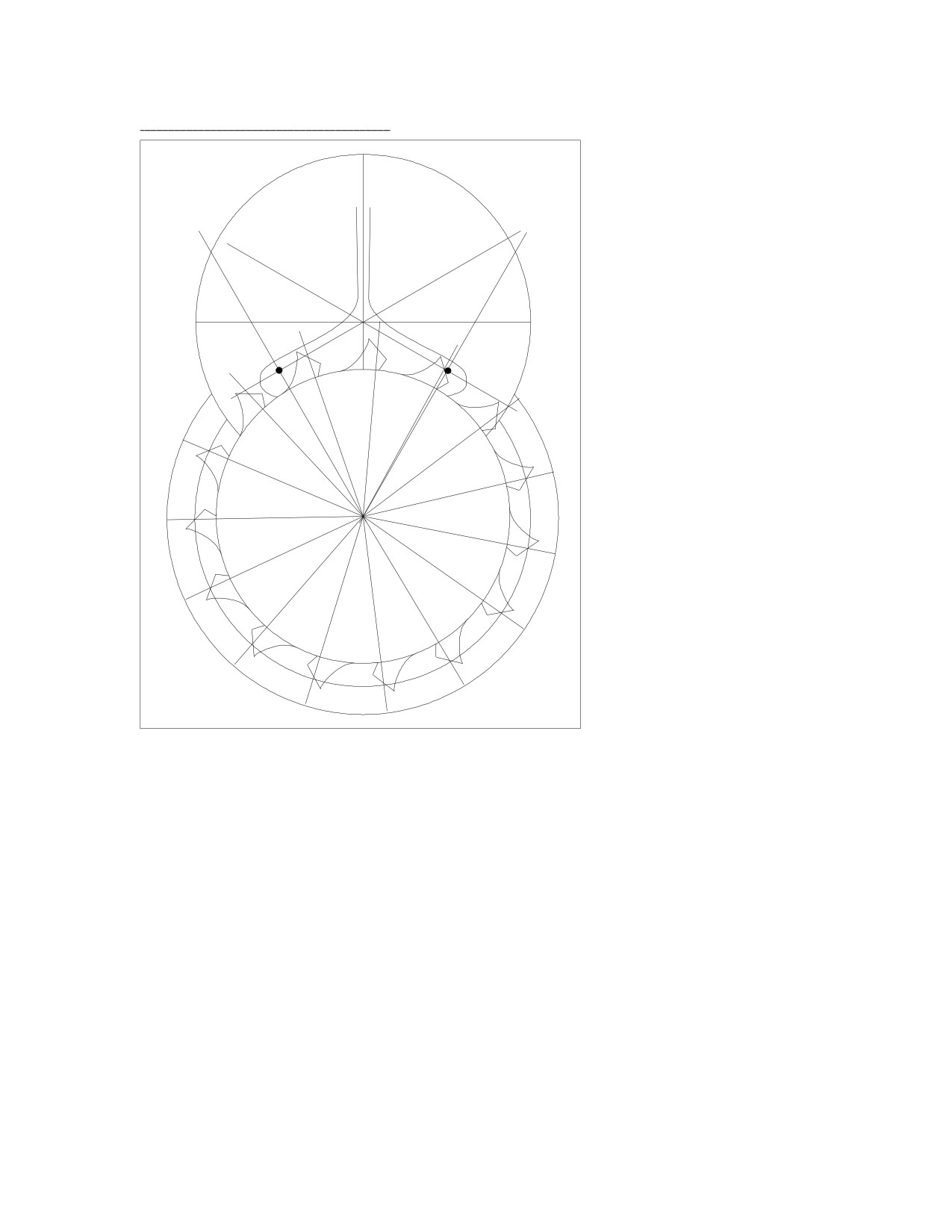
17: The Pin-Pallet Escapement.
You will recognize this
drawing from chapter 9 of
the Clock section. In order
to avoid repetition, I will
discuss only how it differs
from the modern Swiss
Lever Escapement.
In the club-tooth de-
sign, the escape circle radius
of each tooth meets the im-
pulse face and the locking
face at the entrance corner.
In the pin-pallet wheel,
however, the escape circle
radius of each tooth bisects
the impulse face. The
method used for the
pin-pallet wheel is the
correct approach, and it
must be used here. I used
the other method for the
club-tooth escape wheel be-
cause it enabled me to place
the entry pallet in line with
the tooth's impulse face at
the mid-point of the im-
pulse: in other words, to
create a better-looking drawing. The tooth's impulse face was less important because the
relationship between the angles changed during impulse, (see chapter 3). In fact, the last
drawing of the Swiss Lever showed tooth and pallet impulse faces that were not parallel.
The important criteria in the Swiss Lever are the angles of the pallet's impulse and locking
faces, and that the pallet's impulse face always be bisected by the pallet circle's radius line.
In the pin-pallet escapement, the angle of impulse is determined by the tooth's impulse
face rather than the pallet's impulse face, so the tooth's impulse face should always be bi-
sected by the escape radius line, and the angle between these two lines should always be
45º. The pallets are bisected by the pallet circle's radii. The pallets are also bisected by the
escape circle's radii, in order to have equidistant impulse. The amount of lock is deter-
mined by the radius of the pallet pin.
Both escapements were designed with the same number of escape wheel teeth and
with the same number of teeth between the pallets. Therefore, the other design principles
apply to both designs.
60
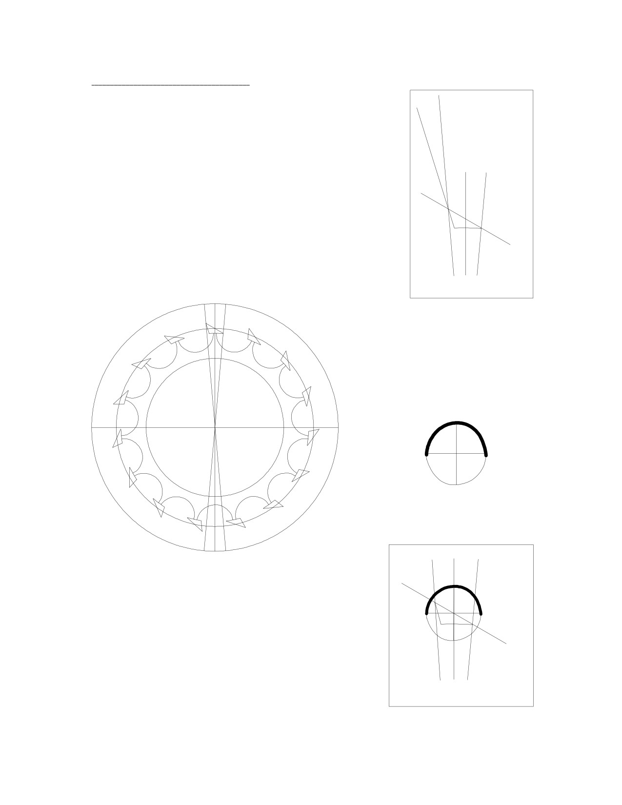
18: The Cylinder Escapement.
Rotate line (1) counterclockwise by 5º to get line (2)
and clockwise by 5º to get line (3). The tooth will occupy a
12º
span of 10º, and the escape wheel will rotate 12º per beat,
so there will be (no less than) 2º left over for cylinder thick-
ness and for drop. Rotate line (1) counterclockwise by 60º
5º
5º
to get line (4); place it on the point where line (1) and the
(5)
six inch diameter circle intersect. Rotate line
(2)
counterclockwise by 12º to get line (5); place it on the
60º
point where lines (2) and (4) intersect. Line (4) will become
the tooth's impulse face. Line (5) will become the back side
of the tooth. Draw a curve between them to form a triangle,
(4)
but give the entrance corner a slightly rounded edge. The
curve could be drawn by tracing it over a six inch diameter
(2)
(3)
circle.
(1)
Rotate the tooth in the 7.5
inch circle by 24º. Draw a curve
to connect the two teeth by trac-
ing over a small circle. Then draw
the escape wheel by duplication
and rotation, as before.
The cylinder will be a circle
with two crossing lines and a
thick curve traced over the edge
of the circle.
The thick curve will cover just over half the cir-
cumference of the circle. The inside diameter of the
curve will be slightly greater than the diameter of the
tooth. I chose a circle diameter of 0.73 inches (by trial
(4)
and error). Place the cylinder such that its center lies on
the point where the six inch diameter circle and lines
(2)
(3)
(1) and (4) intersect.
(1)
61
(2)
(3)
(1)
4 inch
6
7.5
diameter
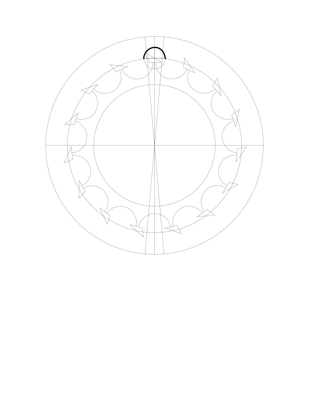
Increasing the diameter of the cylinder circle results in a proportional increase in the
inside drop and an equal decrease in the outside drop.
The tooth impulse face's angle and length determine the lift. The cylinder occupies
just over half a circle in order to create lock: if it occupied half a circle, there would be no
lock.
A tooth impulse face angle of 45º would be more efficient, but this tooth does not fit
inside the cylinder as well as a tooth designed with an impulse face angle of 30º because it
would result in unequal inside and outside drops. In practice, cylinder escapements appear
to have escape tooth impulse faces with angles of less than 30º.
62
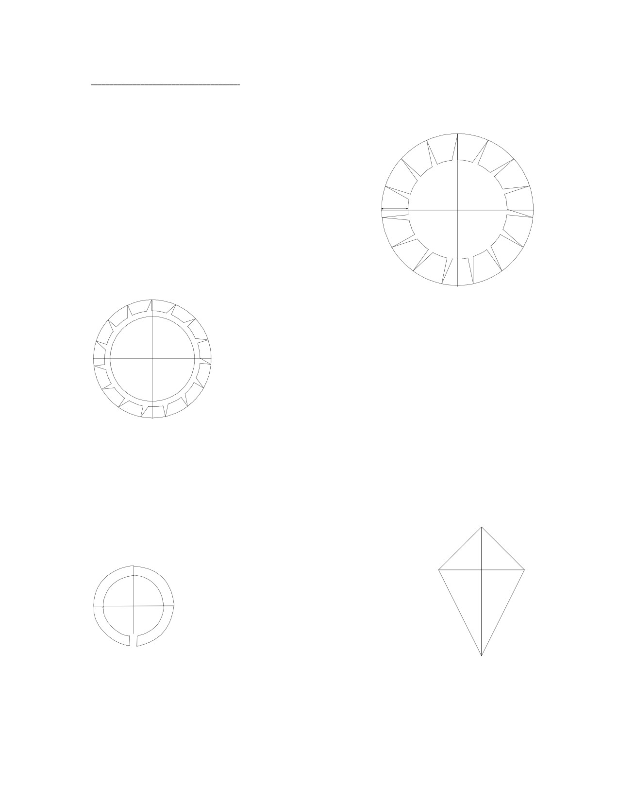
19: The Duplex Escapement.
All the drawings thus far have not included the action of the balance wheel, in order
to simplify the drawings and the simulations. The inclusion thereof complicates everything,
but is certainly necessary in this drawing.
This escapement should be thought of as having
two escape wheels, hence its name. Draw the first es-
1 inch
6 inches
cape wheel in a six inch diameter circle, each tooth
diameter
having a perpendicular locking face and a height of
one inch. This escape wheel has 15 teeth, so there are
24º between each tooth.
The inner escape wheel has smaller teeth, but they are
similar and also have perpendicular locking faces. Draw it
0.33
4.95 inch
in a 4.95 inch diameter circle, each tooth having a height
diameter
of a third of an inch. Both escape wheels need to be
designed so that they could be rotated either together or
independently.
The difficult part is calculating the relationships of the variables: how far from the es-
cape circle center the locking jewel's circle center needs to be, and the diameter of the lat-
ter. If the locking span were taken to be 10º, and the locking jewel's circle center were
placed on a circle 3.25 inches away from the escape circle center, its diameter could be
calculated.
J
J
The radius of the locking jewel would be:
45º
45º
3 sin 5 = J sin 45
J = 3 sin 5 / sin 45 = 0.370"
if the locking jewel rotated
90º during lock.
Draw a circle with a radius of 0.37 inches, and
draw a jewel in it as you wish.
3"
3"
5º
5º
63
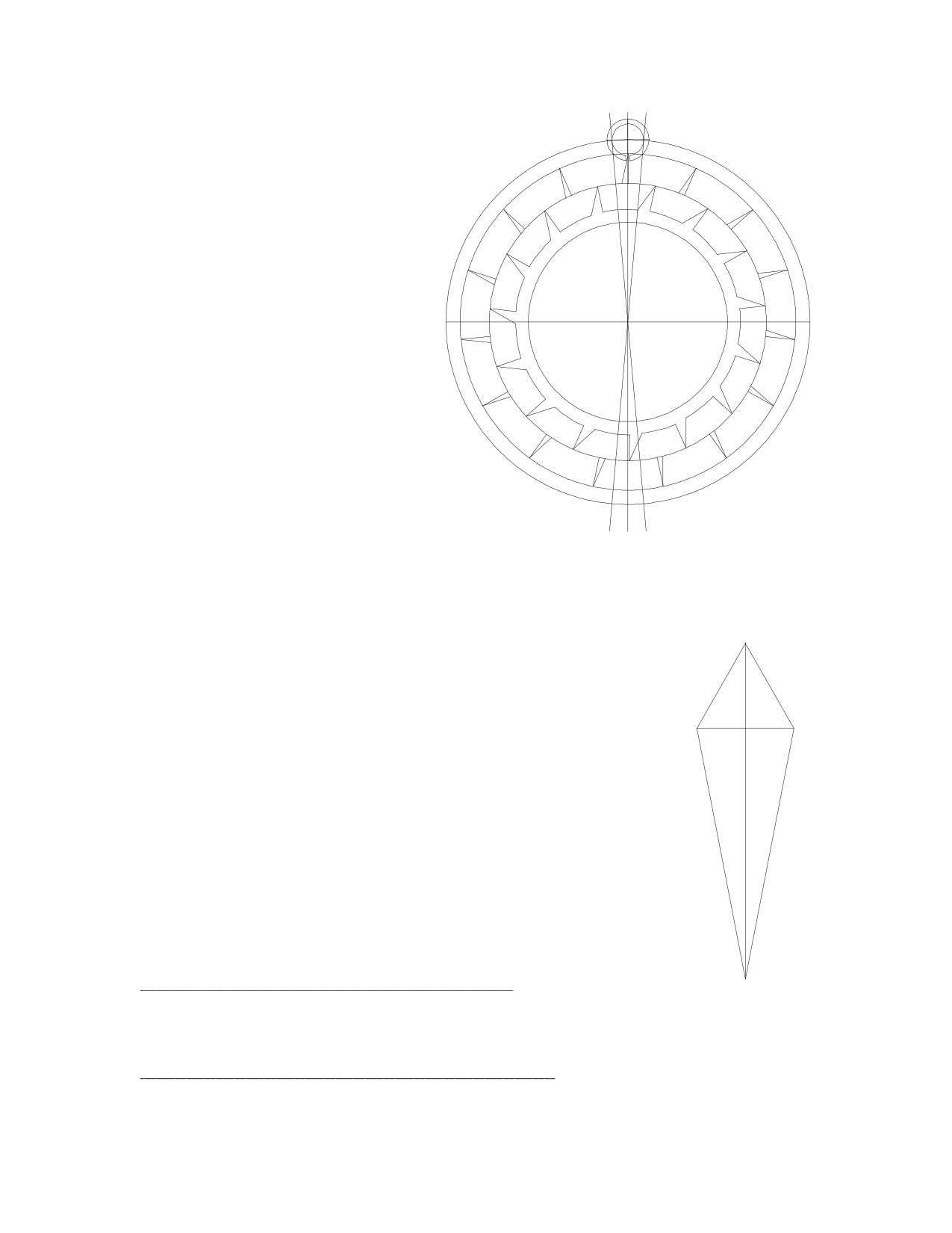
Since the angle between two
escape teeth is 24º, rotate one es-
cape wheel by 12º so that, when
combined, the inner teeth would
appear to be half way between
each pair of outer teeth. Place the
two escape wheels together inside
a larger circle with a radius of 3.25
inches. Place the locking jewel
such that its center lies on the cir-
cumference of the larger circle.
Notice that the escape wheel ro-
tates by 10º during lock.
5º
5º
The impulse arm's length could be found by trial and error, or it could be calculated.
In this example, the impulse arm rotates by 60º during impulse. The escape wheel rotates
by 24º, less 2º for drop, or 22º. The impulse arm's circle radius will be given by 'X', and the
inner escape wheel's circle radius by 'W'.
Y / X = sin 30 = 0.5
X
30º
30º X
Y / W = sin 11 = 0.191
Y
Y
so,
0.5 X = 0.191 W
X = 0.382 W
W
W
X cos 30 + W cos 11 = 3.25
11º
11º
(0.382 W)(0.866) + W(0.982) = 1.312 W = 3.25
W = 2.476
(and 2W = escape circle diameter = 4.952 inches)
X = 0.382 x 2.476 = 0.946
(and 2X = impulse arm's circle diameter = 1.892 inches)
64
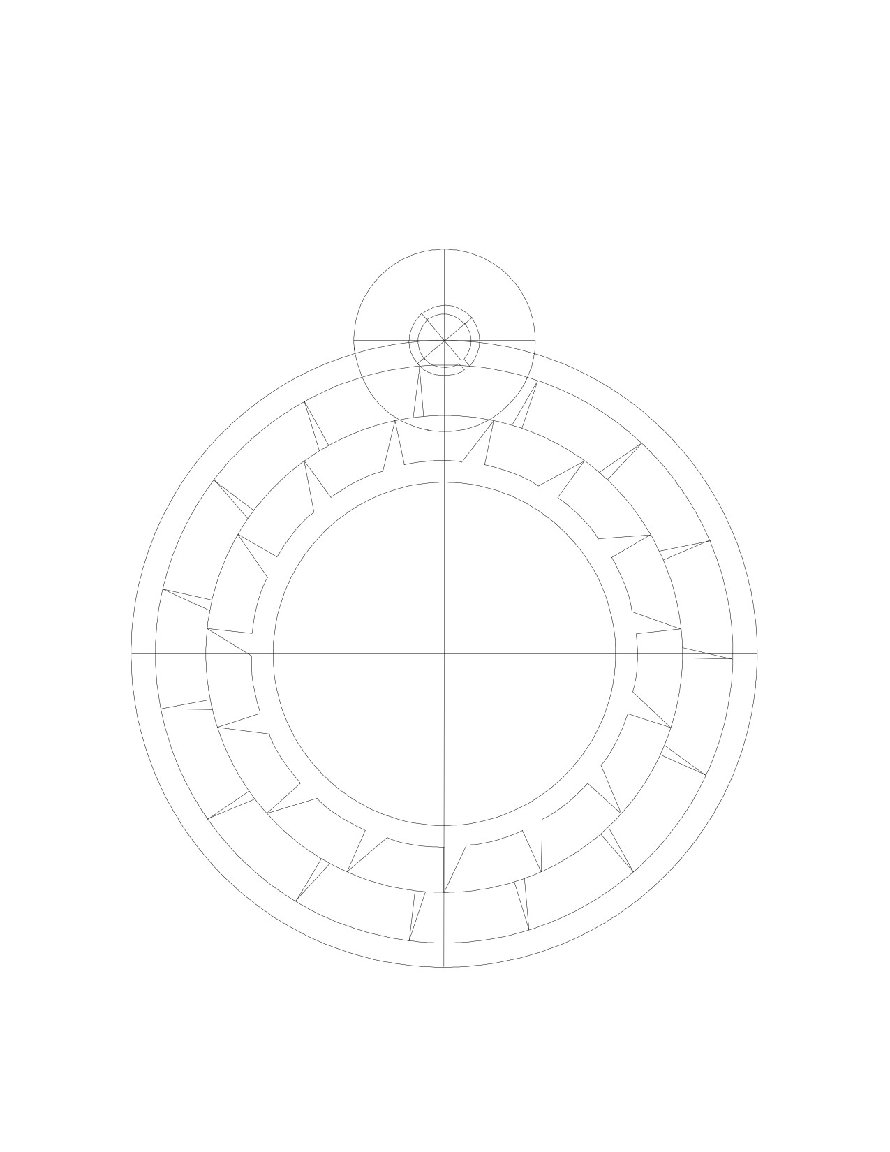
Draw the impulse arm's circle with two lines to indicate its center and with a diameter
of 1.89 inches. Place it such that its center lies on the center of the locking jewel. Rotate
the outer escape wheel clockwise until a tooth touches the locking jewel. Then rotate the
inner escape wheel until the impulse arm's circle becomes centered between two inner es-
cape teeth. Group the two escape wheels so that they would rotate as one.
65