Handbook of Watch and Clock Repairs (1972) - page 5
CHAPTER EIGHTEEN
Chiming clocks
THE strike mechanism has been dealt with in Chapter
17 and so
in this chapter we will discuss the chime mechanism only.
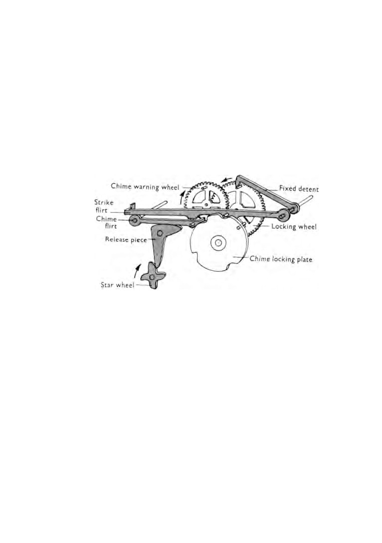
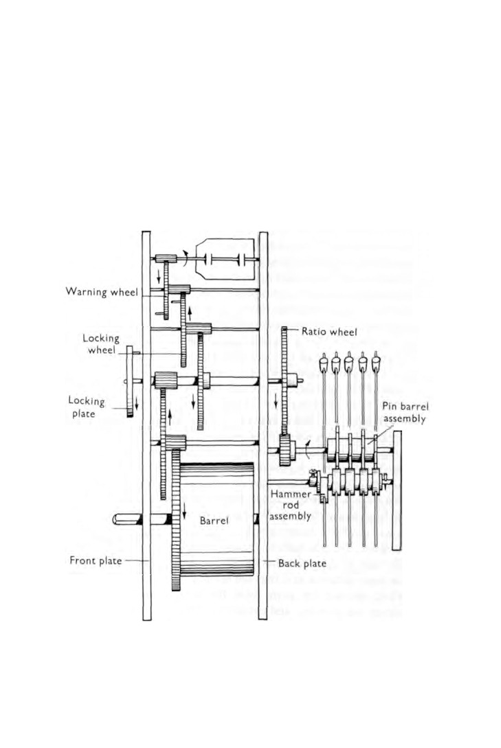
Diagrammatic sketches of the principle of the mechanism are
shown in figures
77 and
78. There are many variations of this
layout but the basic principle remains the same.
Fig. 77. Wheel train.
A star wheel with four arms is attached to the cannon pinion.
The four arms represent the four quarters of an hour. One arm
is longer than the other three and it is this arm that is in use on
the hour.
As the star wheel moves round, the release piece is moved
causing the chime flirt to pivot on its arbor. As the chime flirt
moves it raises the strike flirt.
Secured to the arbor of the strike flirt is a detent with a hook
end. This hook engages with a pin on the face of the locking
wheel which prevents rotation of the chime train.
The strike flirt continues to rise until eventually the detent
releases the locking wheel. This sets the chime train in motion
but in the meantime the release piece has caused the chime flirt
to lift higher and as the chime warning wheel moves round it is
132
CHIMING CLOCKS
133
arrested by the chime flirt catching the pin on the chime warning
wheel. The chime train is now stationary again.
This action takes place a few minutes before each quarter of
an hour and, like the strike mechanism, is known as the 'warning'.
The chime train remains stationary until the star wheel has
moved round to a position when the release piece has been lifted
to the highest point of the star wheel arm. The release piece then
drops and at that moment it is exactly a quarter of an hour.
The action of the release piece dropping causes the chime flirt
Fig. 78. Release mechanism.
134
WATCH AND CLOCK REPAIRS
to fall which in turn releases the chime warning wheel and allows
the chime train to set in motion again. This time however there
is no interruption and the train is free to rotate. In doing so the
chime pin barrel is operated which in turn sets the hammer
assembly in motion.
Immediately the chime flirt falls the chime locking plate lifts
the strike flirt and holds the detent clear of the pin on the locking
wheel. In this position the chime hammers will continue to
function but in the meantime the locking plate is rotating. As it
does so it brings a cut-away portion into line with the pin in the
strike flirt and the strike flirt and detent drop. This causes the
detent to arrest the locking wheel and chiming then stops.
The length of the cam faces on the locking plate are in the
proportion of
1,
2,
3 and 4, each cam length representing that
number of quarters of an hour. Thus on the hour the locking
plate turns with its longest cam, representing four quarters, in
contact with the pin in the strike flirt. This allows the chime train
to rotate long enough for the hammers to strike the four quarters
prior to the hour strike being released.
Just before the pin in the strike flirt drops into the cut-away
portion of the locking plate, a pin in the locking plate engages
the strike flirt and lifts it high enough for the strike rack hook to
be released which releases the strike train. The strike flirt how
ever catches the pin in the strike warning wheel and arrests the
strike train until the full chime has been rung. The strike flirt then
drops into the cut-away portion of the locking plate and the
strike train is released without further interference.
Before dismantling the mechanism study it well. Cause it to
operate until you know the sequence of operations sufficiently
well to be able to assemble the parts without difficulty.
We will assume that the motion work and strike mechanism
have been removed and that the springs have been let down.
First, remove the parts from the back plate. Take off the
hammer rod assembly and the pin barrel assembly, then unscrew
the ratio wheel. Unpin the strike lifting lever. Unscrew the pallet
cock and remove the pallets.
CHIMING CLOCKS
135
Lay the movement on its back over a cardboard box and remove
the release piece, the strike flirt, the chime flirt and the chime
locking plate. The pillar nuts can now be removed and the front
plate lifted off.
As the barrels and flys are lifted out mark them with pencil for
identification: C
(chime) S (strike).
In a movement of this kind there are many points to oil. Those
which are common to all time-pieces have already been mentioned
but with the addition of the chime mechanism there are many
more.
To list them would be quite unnecessary as long as you
remember that any two surfaces rubbing together need lubrica
tion. This does not mean you are at liberty to exercise your skill
with an oil can. The same strict discipline concerning oiling applies
just as much with clocks as it does for watches.
When oiling the friction surfaces of the chime mechanism
the smallest drop of oil will be enough.
CHAPTER NINETEEN
Grandfather clocks
A S P R I N G - W O U N D clock derives its motive power from a
coiled spring but a grandfather clock is powered by weights
suspended from chains or lines of gut.
These weights provide a greater force than a clock spring, and
consequently they are able to overcome resistances which in a
spring-wound clock would cause the movement to stop.
This inevitably results in grandfather clocks functioning con
tinuously for periods far greater than are usually achieved by
spring-wound clocks.
Dirt, dust and lack of oil precipitate the rate of wear. It is a
fact that these clocks collect inside their cases an extraordinary
amount of dirt. With age, the oil partially evaporates and is partly
absorbed by dust. Eventually no oil is left and the moving parts
receive no lubrication.
The force of the weights continues to operate the clock and
wear is therefore accelerated on all friction surfaces. Eventually
this wear becomes so excessive that even the weights are unable
to overcome the resultant resistance.
Examination of a movement in this condition will disclose
badly worn pivots, elongated pivot holes, worn pallets and, quite
often, rusty steel parts.
However, before commencing the dismantling of a grandfather
clock, let us examine it in its case. Sometimes a fault can be found
and rectified without removing the movement from its case which
will set it in motion again. Make sure, of course, that the gut has
not broken allowing a weight to fall to the bottom, or that the
clock only needs winding.
The methods used to secure movements to their seat boards
are often very poor and are a constant source of trouble. The seat
board must be held rigid to the clock case and the clock move
ment must be held firmly to the seat board. The inertia in the
136
GRANDFATHER CLOCKS
137
swinging pendulum tries to pull the movement first one way and
then the other and if the movement is allowed to remain insecure
it may upset the beat.
Make sure the hands are not catching any part of the dial and
are not fouling each other.
Inspect the gut lines for condition and freedom. The gut wears
with usage and becomes frayed. Sometimes the strands foul in the
movement. The lines should hang freely. If they are found to be
rubbing against the seat board, then the slot in the seat board
must be enlarged.
If when the preliminary inspection has been completed the
fault has not been found, the movement must be removed from
the case.
Remove the pendulum and the weights and withdraw the
movement complete with its seat board. Remove the seat board
from the movement. Pull out the collet pin and remove the hands.
Withdraw the dial pins at the back and remove the dial.
If the condition of the movement is bad it will have to be
brush-washed in an assembled condition before an inspection
can be carried out. In severe cases the movement has to be dis
mantled and cleaned and then assembled for inspection.
There is one further examination to be made before dis
mantling the movement and that is of the escapement. Most
grandfather clocks are fitted with the recoil type, so called because
of the reverse movement made by the escape wheel each time a
tooth has dropped from the pallets. It is the amount of drop from
each pallet that has to be checked. To do this we must first
make sure that there is no excessive shake in the pallet pivot
holes and the escape wheel pivot holes. If these pivots are
loose in their holes the drop of the escape wheel teeth will be
affected.
Inspect also the pallets and the crutch for tightness on the
arbor. Any looseness here will also effect the function of the
escapement.
Details of how to check the drop of the escape wheel teeth
will be found in Chapter
16.
138
WATCH AND CLOCK REPAIRS
Check all pivot holes for wear and make a note of those that
need bushing.
The movement may now be taken to pieces, examined and
notes made of any repairs that are needed. The parts are then laid
out in readiness for cleaning.
There are a number of cleaning fluids that can be made up, all
of which do the job very well. A cheap and well tried one is to
mix four ounces of soft soap with two pints of hot water and add
two teaspoonsful of liquid ammonia. Any big hardware store
will supply the ingredients.
When making up the solution stir well to ensure that the soft
soap is completely dissolved. Pour in the ammonia last.
Allow the solution to cool. Place the components in a tray and
pour the solution over them until they are covered and leave them
to soak for twelve hours.
The parts are then lifted out, brush-washed in clean warm
water and dried in warm boxwood dust in a metal container held
over a spirit flame.
Steel parts that have become rusty can now be dealt with. Flat
pieces are best laid on a flat wood block and cleaned with the
finest grade of emery stick. The stick must be held flat and square
to the work and the grain must follow the length or contour of
the part being cleaned. Round parts and flat circular parts are
best held in the turns and cleaned whilst being spun.
If the rust on screws cannot be removed easily, then they are
best renewed.
Rusty pinions can be cleaned by using a folded piece of very
fine emery paper smeared with oil.
We can now go ahead and chalk-brush all the parts. A cleaning
brush with medium bristles will do for this operation. The pivot
holes are next to receive attention. The large holes are best
cleaned with chamois leather. Cut a tapered length and secure the
wide end in the padded jaws of a vice. Feed the narrow end
through the pivot hole to be cleaned and run the plate up and
down the chamois strip a few times.
The smaller holes are cleaned with pegwood. Insert a tapered
GRANDFATHER CLOCKS
139
pegwood stick in the hole, rotate the stick, withdraw it and shave
off the dirt removed from the hole. Repeat this until all the dirt
has been removed. After the pivot holes, make sure that all the
oil sinks are clean.
Now that all the parts have been cleaned and repaired the
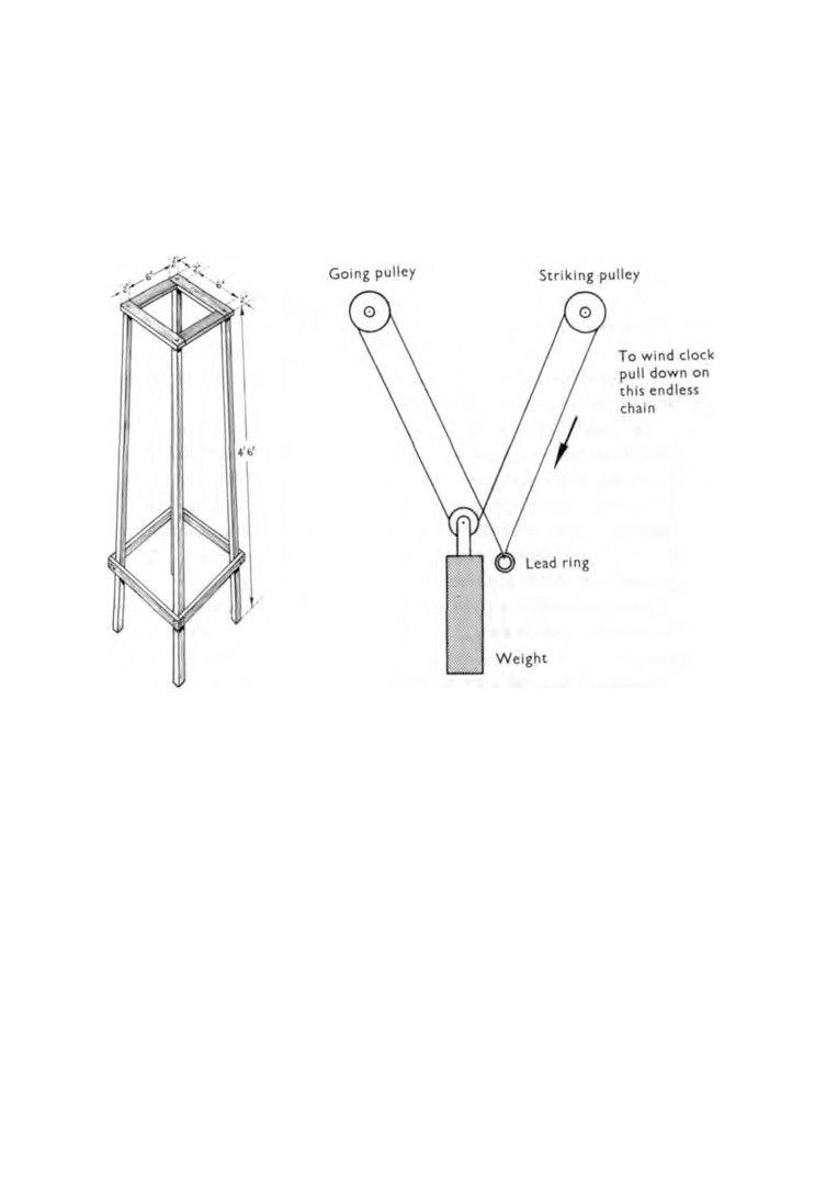
Fig. 79. Wooden stand.
Fig. 80. Method of hanging weight.
movement is ready to be assembled and oiled. Take care to ensure
that all working parts have freedom of movement.
Secure the movement to its seat board and place it on a stand.
A simple wooden stand is illustrated in figure 79. Check the level
of the seat board in both directions with a spirit level. Adjust
ments can be made to bring the seat board horizontal by packing
small pieces of thin card underneath.
Some clocks have only one weight which is suspended on an
endless chain. Figure 80 shows the correct method of hanging the
weight.
Fit the pendulum, hang the weights and partly wind up the
140
WATCH AND CLOCK REPAIRS
barrels. The beat has now to be checked. Move the pendulum
slowly to one side and watch the escape wheel. Immediately a
tooth drops note the angle of the pendulum. Move the pendulum
in the reverse direction and note the angle it makes when the next
tooth drops. The two angles should be the same.
If it is found necessary to move the pendulum further one way
than the other the crutch has to be bent slightly in the direction
of the greater angle.
Continue to adjust until the escape wheel teeth drop with the
pendulum swinging equally each side of the perpendicular centre.
It follows that if the seat board is set horizonally in its case, the
beat of the movement will remain correct.
The pendulum should be quite steady during its swing. If the
pendulum bob can be seen to turn, watch the movement of the
pendulum suspension spring in the slot of the suspension bridge.
The spring should be a tight fit. If the slot is too wide, this will
allow the spring to twist whilst the pendulum is in motion. If no
fault is found here, remove the spring and examine it. These
springs sometimes fracture at the point of flexing.
Check the striking mechanism for correct functioning. Fit the
dial and the hands and the movement is ready to be fitted in its
case.
Support the weights by holding the lines, release the clicks and
slowly lower the weights until all the line has been unwound from
the barrel drums. Remove the weights, lift off the pendulum and
coil the lines neatly.
Before fitting the movement into the case, you will do well to
give the case some attention. With the aid of a plumb-bob and
line check the case to see if it is upright, then with a spirit level
check to see whether or not the case is horizontal.
There are numerous ways of adjustment. A lot depends on
where the adjustment is needed and how much. Packing pieces
can be fitted underneath the case. Blocks can be inserted between
the clock and the wall to push the top of the case forward.
When these adjustments have been carried out lift the move
ment into the case and check the seat board for horizontal.
GRANDFATHER CLOCKS
141
Pack it underneath where necessary and then secure firmly to
the case. Hang the pendulum and the weights and wind the
weights up. Make sure that the lines are correct in the barrel
drum grooves. Push the pendulum to one side and then release it;
the movement should now function.

CHAPTER TWENTY
Carriage clocks
WHEN carriage clocks were made they were intended as travelling
clocks. The movement is encased in glass panels mounted in a
gilded frame. The clocks were supplied with a leather-covered
felt-lined wooden travelling case which was cut away at the front
to expose the dial. On top of the case was fitted a lid with a
spring-loaded snap fastener. Raising the lid exposed the escape
ment which operated on top of the movement. The lid also
Fig. 81. The cylinder escapement.
142
CARRIAGE CLOCKS
143
provided access to the clock carrying handle. To gain access to
the hand-set and to wind the mainspring it was necessary to
remove the clock from its travelling case and open the glass
panelled door at the back. These clocks were made with either a
lever escapement or a cylinder escapement. Because the lever
escapement is dealt with in Chapter
10 we will concern ourselves
here only with the cylinder escapement as illustrated in figure 81.
The escapement consists of a balance, a cylinder and an escape
wheel.
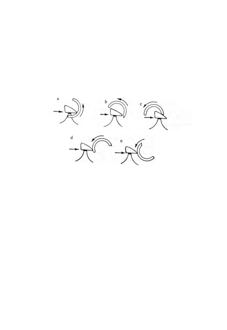
Fig. 82. Cycle of movement.
The balance wheel fits over the upper end of the cylinder and
the teeth of the escape wheel pass through the cut-away portion
at the lower end of the cylinder.
By referring to figure 82 we can see the cycle of movement :
(a) The cylinder has just reversed direction and is commencing
a new swing.
(b) The tooth of the escape wheel is about to leave the cylinder.
(c) The tooth is giving impulse to the balance.
(d) The cylinder has moved round and arrested the next tooth.
(e) The cylinder completes its swing.
Unlike the balance of the lever escapement, the balance of the
cylinder escapement is never free of the escape wheel in that the
escape wheel teeth are at all times in contact with the roller.
144
WATCH AND CLOCK REPAIRS
The escapement is fitted to a platform which is mounted across
the two movement plates. This is known as a horizontal escape
ment, and provided the clock remains horizontal the poise of
the balance remains unaffected.
Because the escapement is positioned horizontally and the
wheel train operates in a vertical plane it is necessary to provide
a means of changing the direction of the motive power. This is
achieved by a contrate wheel, the teeth of which are cut at right-
angles to the rim of the wheel and engage with the leaves of the
escape wheel pinion.
This design is not good gearing practice and it frequently causes
trouble. The meshing of the contrate wheel with the escape wheel
pinion is critical and care must be exercised when making
adjustments.
The movement is held to the base of the case by screws inserted
up through the bottom. Removal of these screws permits the
withdrawal of the movement from the case.
The clock is dismantled in the normal way and made ready for
cleaning. Special attention must be paid to the steel parts that
are gilded, and to lacquered brass. Harsh brushing or the use of
an abrasive will destroy the finish.
Wash the parts in the cleaning fluid and use only a brush with
soft bristle after which all handling should be carried out using
tissue paper or a soft cloth.
The inside of the cylinder must be scrupulously clean. Cleaning
is best done with a tapered pegwood stick.
Any signs of wear on the cylinder lips are best eliminated by
fitting a replacement cylinder. The function of the escapement is
improved by burnishing the edges of the cylinder and the impulse
faces of the escape wheel teeth. The teeth are then cleaned with
a pith stick.
In the final stages of assembly check the end-shake of the
contrate wheel; it should be as little as possible.
Means of adjustment is provided in the form of a screw at the
back of the movement. The screw is held in position friction-
tight by a slotted block. If the screw has become loose, the block
CARRIAGE CLOCKS
145
must be removed and the slot closed. Now fit the platform and
tighten the screws so that they only just nip and then assemble
the escape wheel to the platform.
The depth of mesh between the contrate wheel and the escape
wheel pinion can now be checked. If the escape wheel pivot is
Fig. 83. Tools for removing cylinder plugs.
held by a piece of pegwood and the contrate wheel is rocked it is
possible with the aid of an eye-glass to see the depth of mesh.
An adjustment either way can be made by tapping the end of
the platform in the desired direction.
The screw holes in the platform are slightly oversize to permit
such adjustment to be made. When the depth of mesh is correct
the platform screws can be tightened.
By winding up the mainspring one or two clicks and setting
the wheels in motion an impression is obtained as to whether or
146
WATCH AND CLOCK REPAIRS
not the depth of mesh needs any further adjustment. A noisy
contrate wheel is a definite indication of the mesh being too deep.
If the leaves of the escape wheel pinion are worn, a new surface
can be offered to the contrate wheel by raising the platform. Four
thin collars of equal thickness placed one under each corner will
be sufficient.
Fig.
84. Punching out bottom plug.
Now fit the balance and wind the mainspring up a little more.
Before carrying out any further checks on the escapement it is
necessary to find out if the height of the cylinder is correct in
relation to the escape wheel. From figure
82 it will be seen that
the escape wheel moves only when imparting an impulse to the
cylinder. If, however, the cylinder is too low, allowing the edge
of the cut-away portion to hit against the rim of the escape wheel,
a backward movement of the escape wheel can be seen.
To check this, hold the balance wheel in the tweezers and
slowly move it backward and forward through the normal angle
of swing and observe the reaction of the escape wheel.
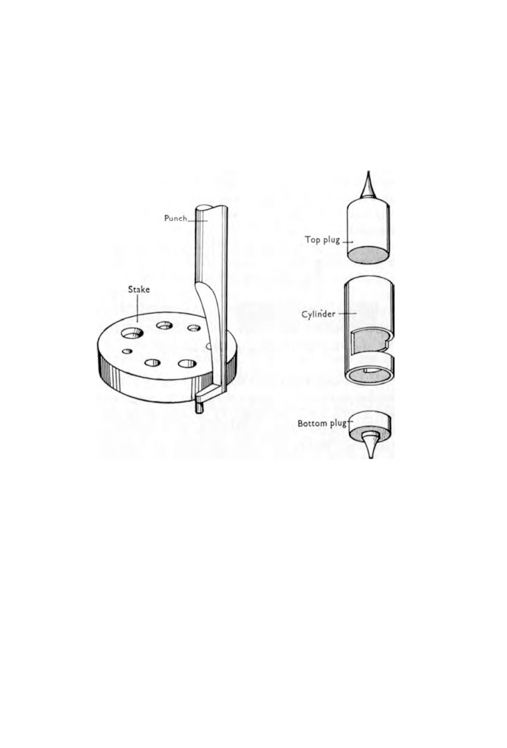
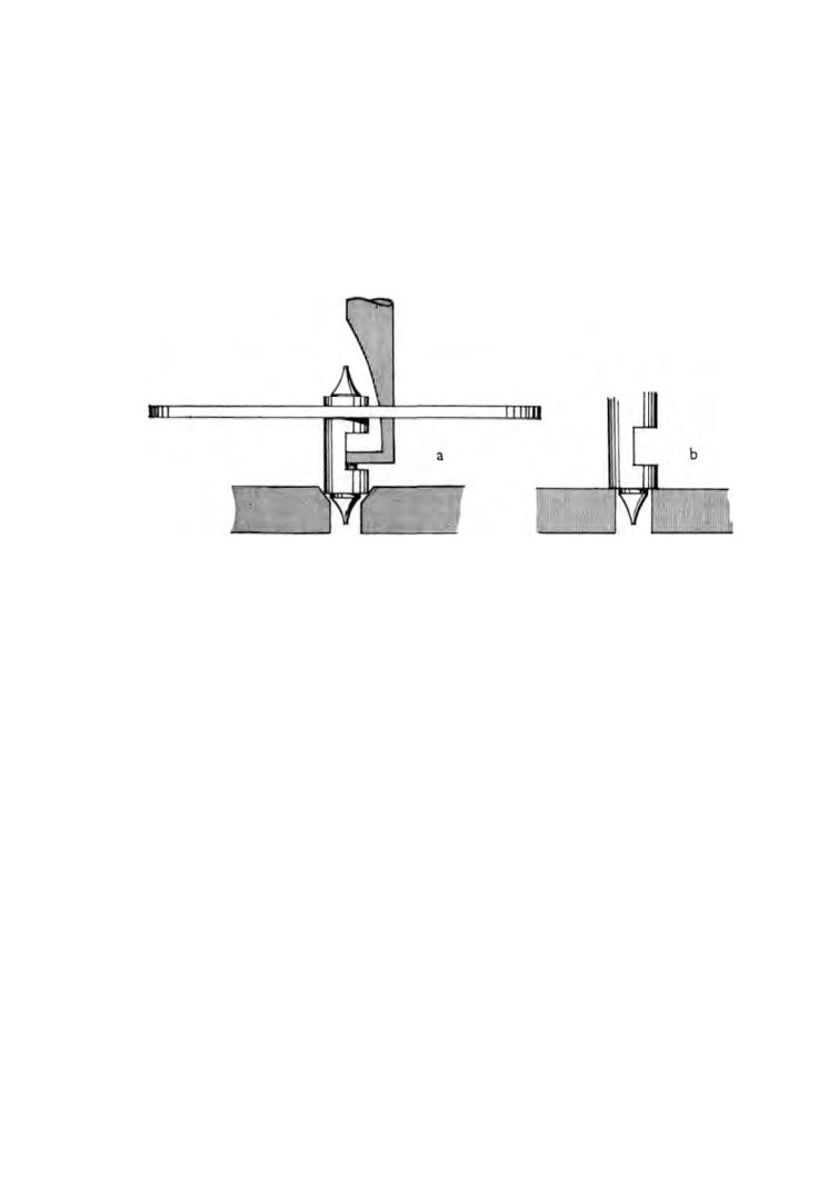
If the cylinder is too low it can be raised by driving the bottom
plug out a little, and then driving the top plug in by the same
amount. The tools for this operation are illustrated in figure
83.
and the method is shown in figure 84. The stake illustrated has
five plain holes and three countersunk holes all of different sizes.
A countersunk hole is selected for size, the cylinder is placed
CARRIAGE CLOCKS
147
in the hole and the plug is partially driven out by the punch. To
completely remove the plug, the cylinder is transferred to a plain
hole the diameter of which will allow the plug to pass through.
We are now ready to check the locking of the escape wheel
teeth. Once again hold the balance wheel in the tweezers and
slowly lead it round until a tooth drops. At this point note the
position of the balance wheel. Now lead the balance wheel round
in the reverse direction and watch the escape wheel very closely.
Immediately the escape wheel starts to move stop the balance
wheel and note its new position. The total distance travelled by
the balance wheel should be 5 degrees.
To assist this check, some manufacturers punch three dots on
the face of the balance wheel, the two outside ones being 5 degrees
from the middle one.
Immediately a tooth drops, a mark can be made on the plate
underneath the centre dot. Then when the balance wheel is led
round to its second position it can be seen whether or not the
5 degrees is being achieved. If it is less, then the locking is
shallow and the cylinder needs to be brought closer to the escape
wheel.
To do this, the platform is removed from the movement and
the chariot screw underneath is loosened. The chariot is then
moved closer to the escape wheel and the screw tightened.
This check must be carried out to all the teeth and with both
inlet and outlet lips of the cylinder.
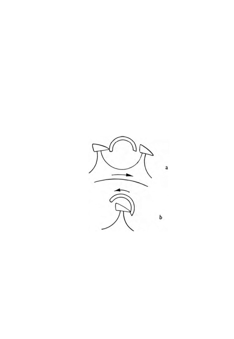
The next check is the shake of the teeth. Lead the balance wheel
into the position shown in figure
85, a. By holding the escape
wheel in tweezers try the shake between the points where the toe
of the trailing tooth touches the inlet lip and the heel of the
leading tooth touches the exit lip.
The balance is now moved into the position shown in figure
85, b. The internal shake can now be tried.
If the inside shake is the greater it is an indication that the
cylinder is too large, and if the greater movement occurs on the
outside of the cylinder then the cylinder is too small. The design
of the escapement will, however, permit a generous tolerance.
148
WATCH AND CLOCK REPAIRS
Only if the inside shake is tight with a very loose outside shake
is it necessary to take rectifying action. The remedy is to renew
the cylinder by fitting one with a larger diameter.
Set in the rim of the balance wheel is a small banking pin which
is arrested by a larger pin fitted in the back of the balance cock.
The purpose of this pin is to prevent the balance wheel from
swinging through an angle greater than
180 degrees in either
direction. If the balance wheel exceeded this amount of swing it
would foul the escape wheel teeth and the movement would stop.
If the balance wheel pin is missing it should be replaced. If it is
worn, broken or bent it should be renewed otherwise there is the
danger of it trying to pass the pin in the balance cock and
becoming fast.
Fig. 85. Checking shake of escape wheel teeth.
CHAPTER TWENTY-ONE
Cuckoo clocks
THE popularity of cuckoo clocks has returned and today there
is a thriving market in Europe catering for the tourist trade.
These clocks are smaller and less complicated than the original
cuckoo clocks and they are less expensive. The originals are fast
becoming antiques and are being sought after by dealers.
It is the older type of clock we are going to discuss because
it is thought that an understanding of this mechanism will
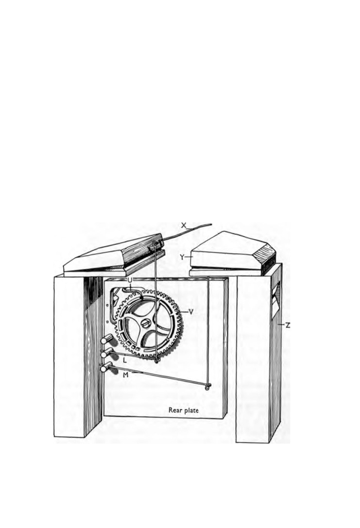
Fig. 86. Rear view of bellows (see Fig. 87 for key).
149
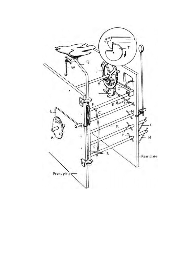
Fig. 87. Strike and cuckoo mechanism without wheel train. A. Cannon
pinion. B. Lifting piece. C. Lifting arbor. D. Raising wire. E. Engaging
pin. F. Locking arbor. G. Fly wheel locking piece. H. Fly wheel pin.
J. Fly wheel. K. Hammer arbor. L. Bellows wire (short). M. Bellows
wire (long). N. Hammer pin. O. Pin wheel. P. Bellows pins. Q. Cuckoo
arbor. R. Cuckoo arbor pin. S. Cuckoo operating pin. T. Locking
wheel. U. Count wheel locking piece. V. Count wheel. W. Door wire.
X. Tip wire. Y. Bellows. Z. Pipe.
CUCKOO CLOCKS
151
undoubtedly result in a working knowledge of a more simple
movement.
Some clocks are weight driven and others are spring-wound
but the method of motive power has no influence over the
striking and cuckoo mechanisms which is all we are interested
in here.
The case is made of wood with a carved front, the whole being
roughly made. The cuckoo door is mounted above the dial and
two inspection doors are fitted one in each side of the case.
Cut in the top of each side is an opening through which can
b e h e a r d t h e s o u n d p r o d u c e d by t h e pipes.
At t h e b a c k of the case is a full-sized p a n e l t h a t c a n be lifted
off leaving an a p e r t u r e large e n o u g h for t h e wi t hdrawal of t h e
movement. On the inner face of the rear panel is mounted the
gong.
Figure 86 shows the back of the movement with the pipes and
bellows positioned on each side. The slot at the top of each pipe
is opposite the a p e r t u r e c u t in e a c h side of the case.
Before taking the movement from its case let us study the
illustrations and find out how the strike and cuckoo mechanisms
operate.
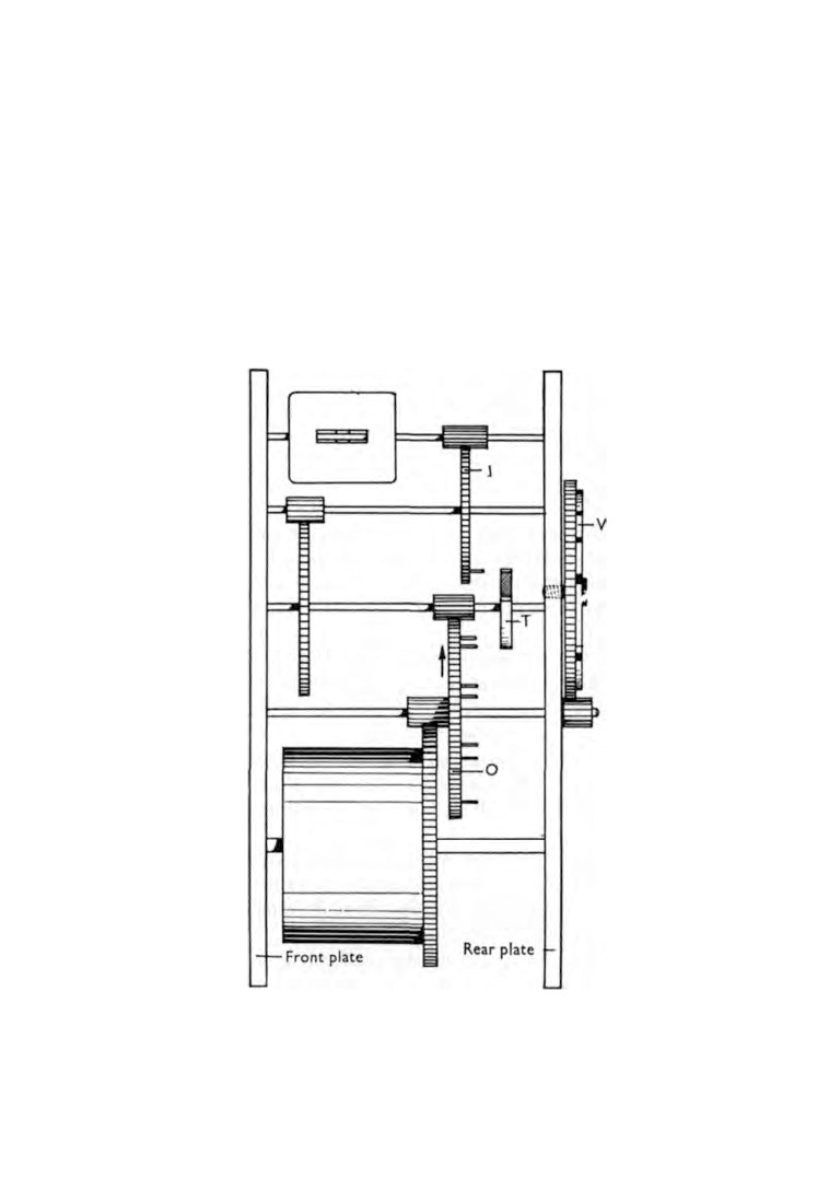
The key in figure 87 applies also to figures
86 a n d 88.
Attached to the rear of the cannon pinion A are two pins
diametrically opposite each other. These pins operate the lifting
piece Β on the hour and the half-hour.
The lifting piece Β is attached to one end of the lifting arbor C
and at the other end the raising wire D is attached. It follows then
that any movement of lifting piece Β is transmitted to raising
wire D.
Placed above the lifting arbor C is the locking arbor F.
Attached to this arbor is the engaging pin E, the fly wheel locking
piece G, the count wheel locking piece U, and the cuckoo
operating pin S all of which move together.
When the raising wire D is lifted it contacts the engaging pin Ε
and turns the locking arbor F.
Until now the hook at the end of the fly-wheel locking piece G
152
WATCH AND CLOCK REPAIRS
has been resting in the recess of the locking wheel Τ and the
tongue at the end of the locking piece G has been arresting the
movement of the fly wheel pin H.
With the turning of the locking arbor F the lifting piece G is
going to be raised and in doing so the pin H is released allowing
the wheel train to function.
Almost immediately after, the pin H is again arrested this time
by the c r o o k in the raising wire D. This brief mo v e me n t of t he
wheel train is known as the 'warning'.
Fig. 88. Wheel train (See Fig. 87 for key).
CUCKOO CLOCKS
153
I n the me a n t i me the c a n n o n pinion h a s cont i nued t o r ot at e
and now the lifting pin moves clear of the lifting piece Β which
drops. It follows that the raising wire D must also drop and in
doing so the fly wheel pin Η is again released and the train of
wheels goes into motion.
Around the edge of the pin wheel Ο are seven pins spaced at
equal distances. As the wheel rotates the pins trip the bellows
pins Ρ causing the wires L and M to operate the bellows. The
same pins then carry on to trip the hammer pin Ν causing the
hammer to operate. Due to the angular movements of the hammer
and the bellows wires, the hammer strikes first followed by the
long bellows wire M sounding 'CUC' and finishing with the
short bellows wire L sounding 'ΚΟΟ'.
When the raising wire D dropped, the locking arbor F swung
round and caused the hook of the locking piece G to drop into
the recess in the locking wheel Τ but the wheel train was in
motion and therefore the cam action of the locking wheel Τ
raised the locking piece G again.
At the same time t h a t the locking piece G is being raised the
count wheel locking piece U is being lifted from one of the slots
cut in the rim of the count wheel V and the pinion on the end of
the pin wheel arbor is causing the count wheel V to slowly rotate.
The result of this action is that when the recess of the locking
wheel T again comes opposite the hook end of the locking piece G,
the hook end is prevented from dropping into the recess by the
locking piece U riding on the rim of the count wheel V.
The rim of the count wheel V is cut into eleven segments each
longer than its neighbour. The strike and cuckoo action will
continue to function for so long as the mechanism is kept in
operation by the locking piece U riding on a segment of the
count wheel V.
When the count wheel V has moved round to bring the next
slot opposite the locking piece U, the locking piece U will drop
causing the locking piece G to drop and the train of wheels will
then be arrested by the fly wheel pin H coming into contact with
the tongue on the end of locking piece G.
154
WATCH AND CLOCK REPAIRS
When the locking arbor F turns, the lower end of the cuckoo
operating pin S moves inward, presses against the cuckoo arbor
pin R and turns the cuckoo arbor Q. This swings the cuckoo
forward and opens the door. When the cycle is complete, the
cuckoo returns under spring pressure and pulls the door shut by
means of the door wire W.
On top of the left-hand bellows is a tip wire X. When the
bellows operate, the tip wire is lifted and it contacts the underside
of the cuckoo lifting the cuckoo's tail up and lowering the head.
This rocking action causes the wings to spread and the beak to
open.
To take the movement out of its case the pipes and bellows
must first be removed. Lift off the pendulum or weights. Dis
connect the bellows wires. The pipes are secured by screws
passing through the sides of the clock case. Remove these screws
and the pipes can then be withdrawn complete with the bellows
which are glued to the top of the pipes. Put them in a safe place
away from possible harm.
Open the cuckoo door and disconnect the wire linking the door
to the cuckoo, and then remove the hands.
All that now remains is to remove the screws holding the
movement to the case and withdraw the movement.
The movement is dismantled and assembled as previously
described in Chapter
18. Cleaning is carried out by washing the
parts in a bath of cleaning fluid and then finishing with the chalk-
brushing method. The illustrations will assist in the assembly of
the strike and cuckoo mechanisms. To check their action after
assembly place the tip of the forefinger on the teeth of the fly
wheel and allow the wheels in the train to rotate slowly.
To repair a broken pipe or even to make a new one is quite
simple. The wood can be cut from a cigar box, shaped and glued.
Bind the pieces together with strands of wool until the glue is set.
When making a new one there are two things that require careful
attention ; the width of the air gap between the bellows and pipes
and the internal depth of the pipes. If either of these is incorrect
the tone or note of the pipe concerned will be affected.
CUCKOO CLOCKS
155
If the bellows are leaking the kid must be removed and a new
piece fitted. Fold the new piece using the original as a pattern.
Press the new piece so that the creases become permanent and
then glue into position.
The following amusing example of horological English was
found on the back of an old clock :
'Indication of the manner to serve Cuckoo Clocks.
At first one draw out the bellows with much circumspection
the paper and the cramps. Further it is necessary to remove the
iron-wire or the packthread which is fixed on the chain. If the
clock no strike correct it is necessary to open the small door
of the right side and to press of the visible wire. If the clock do
hang a little oblique, it is necessary, to bend the wire-sling
(which is visible under the case of clock and as hang the
pendulum) a little of the same side as hang oblique the clock.
By cuckoo clocks with sounding springs one draw the paper
much cautious out the springs. Moreover it is to remove the
fixed iron-wire upper the small door on the front of clock.
Cuckoo and Quail Clocks. As because the strike correct
the Quail, it is necessary to open the small door of the left side
from case of clock and to press of the visible iron-wire. If the
clock march too quick one push the sheave from pendulum
more upwards, if the clock march too slow one push and
sheave more downwards.'
CHAPTER TWENTY-TWO
French clocks
D υ Ε to the n a t u r e of F r e n c h clocks being show-pieces as well as
first-class time-pieces, extra care and trouble is expended during
cleaning.
Fundamentally the sequence is clean, wash, dry and polish.
The recommended cleaning agent is a liquid metal polish.
If this is applied with a stiff watch brush, a very fine finish can
be achieved.
Shake some metal polish into a shallow tin and dip the end of
the brush into it.
The part to be cleaned is held in the hand in a piece of soft
cloth such as an old handkerchief. Brush inside the bars of the
wheels with a side motion so that the grain will follow the
contour of the aperture.
Take extreme care not to knock the pivots with the brush
because apart from being very fine they are also quite hard and
easily snap off.
When brushing the teeth make sure that the brush movement
is m a d e square with the wheel to ensure t h a t the bristles reach the
base of the teeth. Be very meticulous with the gearing and round
the wheels two or three times.
When brushing the sides keep the brush movement always in
the same direction. Never cross the grain.
Plates and other flat pieces are similarly treated, the grain
always flowing with the length of the part.
To clean the oil sinks, place a hand-drill in t he vice a n d secure
in t he c h u c k a short length of pegwood shaped like a flat drill.
Cut a small square of chamois leather, smear it with a spot of
metal polish and place it over the oil sink. Bring the work up to
the pegwood stick and rotate the hand-drill at a good speed
causing the chamois leather to spin in the sink.
When all the brush work is finished, take a leather buff
156
FRENCH CLOCKS
157
(supplied for the purpose) smear a very little metal polish over its
surface and buff all the plates, bridge pieces, etc., retaining the
same direction of grain.
All these parts now have to be washed in a cleaning fluid. Lay
them in a pan of suitable size, pour the fluid over them and with
a 1/2-in. varnish brush remove every trace of the metal polish.
As each part becomes washed lift it out of the tray and lay it
on folded newspaper to absorb the surplus fluid. The parts are
then dried in a linen cloth.
Polishing is carried out with a soft watch brush charged with
billiard chalk. All the parts are brushed as before, but of course,
not so energetically, and for this operation they are held in tissue
paper.
The oil sinks are polished using the same method by which they
were cleaned only this time dry chamois leather is used.
Finally, all pivot holes, threaded and plain holes and pinion
leaves are cleaned out and rubbed over with a pointed pegwood
stick. When cleaning out the pivot holes the pegwood stick is
inserted at both ends and rotated. Any dirt on the stick after
withdrawal is shaved off and the stick is inserted again. This
process continues until all traces of dirt have been removed.
As each part becomes finished it is put in a box away from
dust.
Blued steel screws that have become marked should be restored
to their original condition. This is best done by spinning the
screw in a lathe. Remove the blueing and the marks with a dead-
smooth file, polish with a piece of very fine emery paper and
finish with a flat burnisher.
The screw head must not be touched by hand. Clean out the
screwdriver slot and remove the screw from the chuck with
tweezers.
There are two methods of blueing and preservation. One is to
place the screws on a blueing pan (Fig.
11) and move it about in
a spirit flame until the screw heads turn the right colour and then
tip them into a tray containing thin oil. The screws are then
washed in cleaning fluid.
158
WATCH AND CLOCK REPAIRS
The other method is to place them, head uppermost, in a tray
of hot silver sand supported over a flame. When the head has
turned blue the screw is lifted out with an old pair of tweezers
and given one coat of colourless lacquer with a 1/2-in. flat lacquer
brush.
CHAPTER TWENTY-THREE
Alarm clocks
THERE is a wide range of alarm clocks on the market especially
in the lower-priced models, and different methods of casing are
employed.
Before dismantling an alarm clock it will be necessary to study
the case to understand the design and method of assembly.
It is usual for the back of the case to be marked with arrows
to indicate the direction of turning the winding keys. The reverse
direction will unscrew them.
If the winding-click is broken any attempt to unscrew the key
will only result in the key and arbor turning together. To over
come this, some clocks have a slot machined in the outer end of
the spring arbor. A screwdriver is held in the slot and the arbor
held stationary while the key is unscrewed.
The hand-set button is usually a push-on fit and only needs a
straight pull to remove it. The alarm-set button is removed by
unscrewing it against the direction of setting the alarm.
Sometimes the threads of the feet pass through the case and
into the movement plate preventing the movement from being
withdrawn. Unscrew the feet by wrapping them in two or three
thicknesses of cloth and gripping them in pliers.
The round case is the most common type in the lower-priced
models. The bezel either pushes into the front of the case, or it
forms part of the case and the back pushes in from the rear.
Sometimes the back is held in position by three or four screws.
Having removed the external parts and opened the case, the
movement is now ready to be lifted out complete with dial and
hands.
The minute hand and the alarm hand can be removed by using
the lever shown in figure
10. Now bend back two of the tabs
holding the dial to the movement and remove the dial complete
with the hour hand and hour wheel.
159
160
WATCH AND CLOCK REPAIRS
Take care not to bend the dial tabs any more than is absolutely
necessary because they have to be bent again during assembly,
and too much bending will cause them to break off.
Cut off a short length of pegwood whose diameter will just fit
inside the hour hand. Support the dial in the left hand and place
the tip of the thumb and fingers between the wheel and the dial.
Push the pegwood punch into the hour hand and gently tap the
punch until the hour wheel and the hour hand separate.
It is unlikely that any work will have to be done on the dial
or hands and so, when they are free, put them in a safe place
away from the possibility of damage. If the hands and dial
numerals have been coated with luminous paint, extra care must
be taken during handling to prevent the paint from cracking.
Pull out the alarm wheel pin and remove the alarm wheel.
Before dismantling the movement, the escapement must be
examined. The majority of the lower-priced alarm clocks are
fitted with the pin-pallet type of escapement and it is therefore
necessary to read Chapter
10 in conjunction with this chapter.
If when checking the shake of the lever against the balance staff
it is found that the shake is unequal, the lever can be bent side
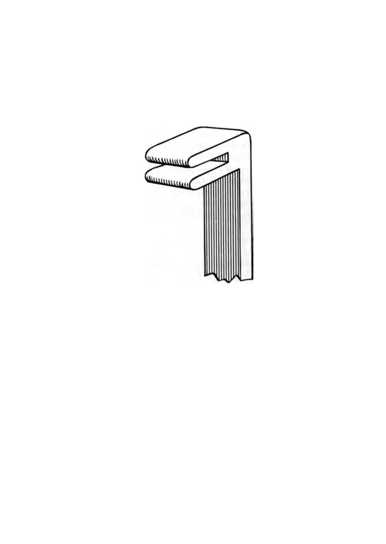
ways without removing it from the movement. A suitable tool for
this purpose can be easily made and is illustrated in Figure
89.
Having completed the inspection of the escapement, the balance
may now be removed. Pull out the balance spring pin from its
stud and guide the spring out of the stud and index pins. Slacken
off the upper balance bearing screw and remove the balance
from the movement.
With a pair of tweezers check the end-shake and side-shake
of the wheel train pivots and the pallet pivots. Any pivot holes
that have become enlarged should be noted. They can be dealt
with after the movement has been dismantled.
Fully wind the mainspring and the alarm spring and hold them
in this position by fitting spring clamps.
Place a piece of pegwood through the escape wheel and
operate the lever continuously until the pegwood prevents any
further rotation of the escape wheel.
ALARM CLOCKS
161
Slacken the plate nuts just enough to lift the lever from the
movement. Tighten the nuts, remove the pegwood from the
escape wheel and allow the wheel train to rotate until the spring
clamps prevent any further movement of the springs. When the
wheel train comes to rest, the plate may be removed and the
wheels lifted out.
Fig. 89. Tool for bending lever.
In many alarms the cannon pinion is a driving fit to the centre
arbor, and, once removed, may be always loose on the arbor.
It is better therefore to leave this undisturbed and clean the pivot
hole below the pinion by soaking and careful brushing.
Having dismantled the movement and laid out the parts
separately we can now continue with the inspection.
Examine the balance staff ends for wear. Usually it will be
found that the conical faces have worn away and produced a
ridge. To rectify this the balance spring must first be removed.
Mark the balance wheel to show the position of the collet. Make
a tool similar in shape to a watch screwdriver but with a longer
taper and push the blade into the slot of the spring collet.
A slight twist and pull made in one movement will remove the
collet and spring from the balance staff.
Fit the staff in the turns and with an Arkansas stone restore
162
WATCH AND CLOCK REPAIRS
the conical face making sure that the original angle is not
destroyed. Burnish the new face and the point. Treat the other
end of the staff in the same way.
Examine the pallet pins for wear. If they need renewing the old
ones can be tapped out over a graduated stake. New pins can be
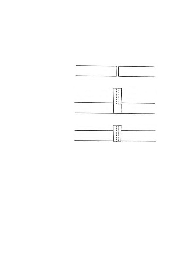
Worn pivot hole be
fore reaming.
Pivot hole after ream
ing, showing entry of
tapered bush.
Bush pressed into
position ready to be
filed to length.
Fig. 90. Fitting Bush to worn pivot hole.
made from sewing needles. Cut off a suitable length and tap the
new pin in position from the underside of the lever.
Enlarged pivot holes can now be dealt with by fitting new
bushes.
Bushes are supplied ready made. The pivot hole is drilled and
the outside diameter is machine tapered. Each bush is made
oversize in length.
A convenient m e t h o d of purchasing is to obtain from any
materials supplier a box containing bushes of assorted sizes.
Select a suitable bush and ream out the worn pivot hole
from the back of the plate until the diameter of the hole will
just allow the small end of the bush to enter. The bush can
then be pressed or tapped into position.
ALARM CLOCKS
163
When the bush is in tight both ends must be carefully filed
flush with the plate.
Finally the pivot hole is enlarged by reaming, to suit the size
of the pivot.
Examine the wheel train for broken teeth. New teeth can be
fitted as described in Chapter
6, but in place of brass pin-wire,
strip brass will probably be needed.
Examine the wheel pivots and if wear has taken place the
pivots must be polished and burnished in the turns.
Provided no other repairs have to be carried out we are now
ready to proceed with the cleaning. A tray will be required for
the cleaning fluid about two inches deep and large enough to take
the back plate. We will require some tissue paper, two cleaning
brushes, soft and medium, a 1/2-in. flat paint brush, pegwood, pith,
chalk, a piece of clean soft linen such as an old handkerchief and
some cleaning fluid.
Place one of the plates in the tray and pour the cleaning fluid
over it until it is covered. Brush it with the 1/2-in. brush and when
it is thoroughly clean remove it from the cleaning fluid and dry
it in the cloth. Treat the other plate in the same way.
The balance spring is held in the tweezers and gently washed
in the cleaning fluid by moving it about. When it is clean, lift it
out and place it between two pieces of tissue paper changing the
paper each time it becomes saturated.
Do not immerse the mainspring and the alarm spring in the
cleaning fluid because, in their wound condition, they will not
dry.
Wash, brush and dry all the remaining components in the same
way as was done for the back plate.
Take the cleaning brush with the medium bristles and charge
it with chalk. Rub it briskly over the faces of both plates. This
will produce a semi-polish which is less likely to attract dust.
Treat the wheels in the same way making sure that the spaces
between the teeth are clean.
Lay the balance spring on a piece of white paper. Take the
cleaning brush with the soft bristles and charge it with chalk.
164
WATCH AND CLOCK REPAIRS
Hold the balance spring down with the tip of a finger and carefully
dab the bristles of the brush into the coils of the exposed portion
of the spring. Continue round until the complete spring has been
cleaned.
The pivots, pivot bearings and pinions now need attention.
Shave a point on the end of a piece of pegwood, insert it in the
pivot bearings and lightly rotate it. This will ensure that all
bearings are clear.
The point of the pegwood is now used to clean the pinions.
Run the pegwood up and down each leaf removing any dirt
that may be present.
The pivots are cleaned by pushing them into the end of a pith
stick and rotating the pith a few times.
Having cleaned and polished all the parts we are now ready
to assemble them.
Oil the ratchet wheels and clicks and fit them to the back plate.
Place the balance and lever to one side and assemble the remaining
parts to the back plate.
Lower the front plate into position gently guiding the pivots into
their respective bearings. Make quite sure the wheel train is free-
running, tighten down the front plate and again check the
freedom of the wheel train.
The lever may now be fitted by slackening the front plate nuts,
lifting the front plate slightly and inserting the lever into position.
Lower the front plate again, check the lever for freedom and
tighten the front plate nuts.
The mainspring may now be fully wound up and the clamp
removed. Check the action of the wheel train and the escapement
lever by operating the pallets a few times.
We are now ready to assemble the balance. Support the balance
wheel by placing the lower pivot in a stake. Place the collet on the
upper pivot and with a tubular punch gently tap the collet into
position. By inserting the tool previously mentioned in the slot
of the collet, the collet can be turned until it coincides with the
mark made on the balance wheel during dismantling.
The position for the collet on the staff is determined by the