Handbook of Watch and Clock Repairs (1972) - page 2
OVERHAULING AND CLEANING
37
shake. With a pair of tweezers hold the hour hand by its socket
and lift the hour wheel up and down. If there is no end-shake
remove the minute hand and try again. If end-shake is now
present it indicates that the hour hand or the hour wheel pipe is
fouling the minute hand and that it is necessary to lower the hour
hand on the hour wheel or reduce the length of the hour wheel
pipe.
If, however, removal of the minute hand makes no difference
look to see if the hour wheel pipe is fouling the dial hole or if the
hour wheel is binding on the cannon pinion.
The latter two faults will also eliminate side-shake which is the
next check to make. Additionally, if the depth of mesh between
the hour wheel and the minute wheel pinion is excessive the side-
shake will be reduced or eliminated altogether. It is essential that
the hour hand has complete freedom of movement in both
directions otherwise the resistance offered up will have a retarding
effect on the time-keeping of the watch if not stopping it com
pletely.
Remove the minute hand and the hour hand with the levers
illustrated in figure
10, and at the same time take precautions
against damaging the dial by placing beneath each lever a piece
of folded tissue paper. Hold the levers, one each side of the hand
to be removed, and by applying light equal pressure downwards
the hand will come away. The seconds hand is removed by the
action of lifting off the dial.
The movement may now be taken from its case. There are a
number of methods used to secure movements so let us consider
those that we are most likely to meet.
The movement of a keyless watch fitted to a two-piece case,
such as is illustrated in figure 69, is made to slide into the case and
is held in position by the bezel. To remove it pull out the winder
into the set-hand position and by holding the winder gently ease
the movement from the case. The use of a small screwdriver as a
lever will assist this operation if the movement sticks and fails
to lift out squarely.
The keyless watch with the three-piece case is rather different.
38
WATCH AND CLOCK REPAIRS
The movement, less the winding stem, is put into the case middle
from the front and is prevented from passing right through by the
aperture of the case middle being smaller at the back.
The movement is held in position by dog screws, usually two
in number. These screws have large diameter heads and are
inserted at the back of the movement. In screwing them into the
watch plate the heads tighten on to a lip of the case middle and
hold the movement secure.
Some dog screws have almost half of their heads cut away.
These screws only have to be turned slightly to bring the flats of
their heads in line with the case lip and the movement is freed
without the necessity of removing the dog screws.
With these watches the winding stem passes through the case
middle before entering the movement and is therefore inserted
after the movement is in position.
To take the movement out, slacken the pull-out piece setting
bolt, withdraw the winding stem, slacken or remove the dog screws
and carefully push the movement forward and out.
Some of the earlier key-wound watches have their movements
hinged to the case middle with a spring catch diametrically
opposite to hold it. To take the movement out necessitates the
removal of the hinge pin.
Whatever the method used, however, careful examination will
indicate the procedure for dismantling.
Having taken out the movement we now have to lift off the
dial. In the majority of watches the backs of the dials have two
copper feet soldered diametrically opposite each other. These
feet pass into holes in the bottom plate and are secured by
screws entering the bottom plate from the side. Slackening of
these screws frees the dial. Usually a little assistance is required
because the screw tension causes slight bending of the feet
preventing them from being lifted straight out. Insert a thin blade
of a pocket knife under the dial close to the feet and slightly twist
the blade so that the pressure on the dial takes place at the base
of the feet. This method will prevent the dial from bending, a
precaution which is essential with enamel dials in particular to
OVERHAULING AND CLEANING
39
prevent cracking of the enamel. When lifting the dial off take care
not to lose the seconds hand if there is one fitted.
Another method used to secure the dial is the fitting of dog
screws.
These screws have a conical flange half way down their length.
One side of the flange is cut away. The screw is inserted in the
plate parallel and adjacent to the dial feet and turned so that the
edge of the flange passes into a slot cut in each dial foot. By
rotating the screws half a turn inward the cut away portion faces
the dial feet and enables the dial to be withdrawn.
The dials of some of the cheaper watches are made with small
tongues on the edge that are bent over to grip the movement when
the dial is in position. When these tongues have been bent a few
times they snap off and means of securing the dial are lost.
In handling a dial of this kind it is essential that the tongues are
bent as little as possible.
Having removed the dial inspect the underside for signs of
fouling. The dial may have been pressing on the minute wheel
pinion. If this happens the timekeeping will be erratic. The
minute wheel pinion may bind only in certain positions. When the
watch is not being worn the pressure of the dial on the pinion
may just be sufficient to stop the movement, but the action of
disturbing the watch may cause the movement to function again.
During the time the watch is worn the effect may be a slowing
down at intermittent periods.
Should there be some doubt as to whether fouling is taking
place, a drop of oil on the pinion can be used as an indicator.
Replace the dial, operate the hand-set and rotate the motion
work. Remove the dial and inspect again. Any trace of oil on the
underside is an indication that there is insufficient clearance
between the dial and the minute wheel pinion.
There are two methods of increasing this clearance; by remov
ing metal from the underside of the dial or by reducing the height
of the minute wheel pinion.
In the case of a metal dial take a chamois leather and fold it
into four thicknesses and place it on a flat block of wood on the
40
WATCH AND CLOCK REPAIRS
bench. Over the chamois leather place two thicknesses of tissue
paper, then lay the dial face downward on it.
Scraping is done with the tip of a very sharp knife. The strokes
must be as light as possible to prevent bruising of the dial face.
Continue scraping until all the pinion marks have been removed
and then fit the dial to the movement and test again by the oil
method.
To reduce the thickness of an enamel dial a carborundum stick
is required. These are made specially for the job and can be
obtained from your supplier.
Support the dial as for a metal dial. Moisten the carborundum
stick in water and rub it fairly heavily over the affected area in a
circular motion. Continue this grinding action until all traces of
fouling have been removed or until the copper dial shows through.
If the copper does show before the pinion marks have been
removed then it is advisable to stop work on the dial and have
the height of the minute wheel pinion reduced in a lathe.
Earlier in the chapter it was mentioned that before removing
the hands, a little side pressure should be given to them to find
out if they were tight on the wheels. In the case of the minute
hand although the hand may have been tight on the cannon
pinion, nevertheless the cannon pinion may have been loose on
the centre arbor.
This is a very common fault with the snap-on type of cannon
pinion and is a constant source of trouble.
The centre arbor is machined with a groove all round it. The
cannon pinion is similarly machined and the base of the groove
is then burnished inward causing an internal bulge. It is this
bulge that locates the pinion on the arbor and provides the
friction drive.
The remedy against slipping is to reburnish the cannon pinion
groove until it grips the arbor once again.
Lift off the minute wheel and check the tightness of the minute
wheel post. Then hold the minute wheel between finger and thumb
and grip the minute wheel pinion by inserting the points of the
tweezers between the leaves. Rock the tweezers to find out if the
OVERHAULING AND CLEANING
41
minute wheel is loose on the pinion. Replace the minute wheel
on its post.
Depthing of the wheel teeth must now be tried. First remove
the hour wheel and try the depthing between the cannon pinion
and the minute wheel. Then replace the hour wheel and try the
depthing between the hour wheel and the minute wheel pinion.
After carrying out these checks the wheels must be rotated so that
depthing can be tried with a different set of teeth. Repeat this
until each wheel and pinion has been tried in four different
positions.
On the bench in front of you place a sheet of stiff white paper
on which the parts can be placed as they are removed from the
movement. The parts should be kept together in groups complete
with any screws. Sometimes the screws in one group are similar
but one is slightly longer than the others. It is important that a
screw is not used where a shorter one should be. There is the
possibility of the end of the thread fouling something which may
prevent the screw from being tightened or may cause the watch
not to function.
The screws should, therefore, be placed in or near to their
respective holes in the part to which they belong.
Now turn the movement over in readiness to remove the
balance.
With the mainspring partly wound carry out an inspection of
the escapement and make notes of any faults. Details of this
inspection are contained in Chapter
10.
If the watch is fitted with a cylinder escapement the mainspring
must be let down before the balance is removed, otherwise the
train of wheels will be driven by the mainspring at high speed
which will invariably lead to damage of the pivots.
To let the mainspring down hold the winding button, or the
key in the case of a key-wound watch, and make a slight turn in
the direction of winding. This will partly raise the click which can
then be fully released from the ratchet wheel by the point of a
pegwood stick.
The tension of the mainspring is now directly transmitted to
42
WATCH AND CLOCK REPAIRS
the winding button which, if allowed to rotate slowly between the
finger and thumb, will permit the mainspring to unwind.
Care must be taken not to let go of the button whilst the click
is held back because the mainspring will then unwind itself at
high speed and cause damage to its centre. If it is felt that finger
control of the button is being lost, release the click into the
ratchet wheel and try again.
When the movement is in this position it must not be laid on the
bench and worked on because the centre arbor that carries the
cannon pinion and the fourth wheel pivot that carries the seconds
hand will be projecting.
Either the movement rests at an angle on the bench and is
supported in the hand, or a watch movement stand must be used.
Adjustable stands can be purchased but a length of metal tube
about
1 1/2 in. long, squared at the ends and of suitable diameter
will do quite well.
Take out the screw holding the balance cock and very carefully
lever the balance cock up. A small notch will be seen on the edge
of the cock into which the blade of a small screwdriver can be
inserted. Because the leverage will be concentrated at one end
there will be a tendency for the cock to press down on the
balance pivot at the other end. This must be prevented and once
the balance cock has been moved it must be brought level again
by raising the other end in tweezers.
Once the balance cock pins have been withdrawn from the
bottom plate the cock can be lifted from the movement with the
balance wheel and spring hanging from it.
You may find there is a tendency for the balance wheel to
catch and not come away. This will be because the roller is
caught in the lever fork. If this happens any further attempt to
lift the balance will only result in the coils of the hairspring being
pulled out.
To free the roller, the cock is held stationary above the move
ment, and the movement is slowly turned until the roller is
freed.
Lower the balance to the bench and when the bottom pivot
OVERHAULING AND CLEANING
43
touches the paper roll the cock over on its back. In doing this the
spring will cause the balance wheel to do the same. The balance
wheel is now held in the tweezers and positioned so that the
balance pivot rests in the jewel hole in the regulator index.
The balance now has to be separated from the cock. First,
examine the index pins. Some watches are fitted with one fixed
pin and one movable pin. The movable pin has a lip on the top
that bridges the gap between the two pins and so prevents the
outer coil of the hairspring from coming out. This movable pin
has a screwdriver slot in the end enabling the pin to be turned
thus swinging the lip clear and making it possible for the hair
spring to be removed.
Now remove the stud from the balance cock. Studs are either
held in by a screw or they are a push fit. If the stud is the latter
type, grip it firmly with a pair of strong tweezers and gently ease
the stud out, taking care not to alter the bend or set of the hair
spring.
Lift the balance clear and place it on the white paper along with
the balance cock screw.
It is advisable at this stage to leave the index assembled to the
cock and remove it only when you are ready to clean it.
If the movement is not fitted with a cylinder escapement then
you will not have unwound the mainspring.
The pallets are next to be removed and so we must let the
mainspring down.
Having done this, remove the screws from the pallet cock, lift
the pallet cock away and remove the pallets.
If the wheel train starts to rotate, it is only because by releasing
the click from the ratchet wheel it is not possible to completely
let down the mainspring. However, what little energy remains in
the spring quickly spends itself with no damage to any part.
Before removing the wheels, turn the watch over so that the
cannon pinion can be removed. Because the cannon pinion is a
friction tight fit on the centre arbor all that is required to remove
it is a straight pull. Care must be taken, however, in avoiding
damage to the pinion when it is being held. One of the safest and
44
WATCH AND CLOCK REPAIRS
most simple methods is to grip the cannon pinion in a pair of
brass-faced pliers.
With the cannon pinion removed turn the movement over
again.
Before proceeding with the dismantling of the wheel train we
must test the depthing. Take a pegwood stick and shave it to a
blunt point. Press the end of the stick on to the fourth wheel pivot
and hold the wheel. With another pointed pegwood stick touch
the third wheel and try the shake of the third wheel teeth in the
fourth wheel pinion. Repeat this process for the other wheels.
In Plate IV it will be seen that the escape wheel, fourth wheel,
third wheel and the centre wheel are all held in position by a train
wheel bridge. This arrangement does not apply to all watches.
In some movements the centre wheel is held in by a top plate and
the remaining wheels are supported in the same cock or bar. Then
there is the bar movement in which each wheel has its own bar.
This method is preferred by many watch repairers but the other
methods have obvious advantages.
Remove the screws from the wheel train bridge and carefully
lift the bridge off. Some bridges will have small notches similar
to that previously mentioned in the balance cock for the insertion
of a lever. The bridge or cock has locating pins underneath and
as soon as they are free of the bottom plate the bridge will come
away. Lift out the wheels and place them with the bridge and the
screws.
Now remove the click, click spring, transmission wheel and
ratchet wheel from the barrel bridge. Some watches are fitted
with transmission wheel screws with a left-hand thread and this
must be borne in mind when attempting to loosen the screw. It
is as well to get into the habit of trying to turn the screw first one
way and then the other slowly increasing the pressure until the
screw eventually turns.
Remove the barrel bridge and lift out the mainspring barrel.
This leaves the bottom plate with the balance endpiece and the
keyless work.
Lift the crown wheel and the castle wheel from the plate.
OVERHAULING AND CLEANING
45
Remove the pull-out piece check-spring, the pull-out piece screw
and the pull-out piece itself. Lastly remove the winding stem.
Remove the balance endpiece screw and allow the endpiece to
drop out. If the oil keeps the endpiece in position take a pointed
pegwood stick and turn the endpiece. Now with the same stick
the endpiece can be pushed out from the other side of the bottom
plate by inserting the stick in the endpiece screw hole.
The dismantling of the watch is now complete with the excep
tion of the balance cock index and the mainspring barrel.
It is the intention t h a t these t wo assemblies r e ma i n as they ar e
until we are ready to clean them.
O n the b e n c h i n front of us we n o w have all t h e p a r t s on t h e
sheet of white paper. The parts have been placed together in their
groups and we have made quite sure that the screws have been
placed in or alongside their screw 'holes.
This grouping of the parts will considerably ease the task of
assembly as you will see when you first tackle the job.
We are n o w ready to start the cleaning and so we will c o m m e n c e
b y getting together o u r e q u i p m e n t a n d materials.
The parts are washed in a cleaning fluid (see Chapter 2). A small
clean pan will be required for use as a washing bath. A pan
measuring 3 in. x 2 in. χ 3/4 in. will be sufficient.
Two watchmaker's brushes will be required, one with medium
bristles and the other with soft bristles, and a block of billiard
chalk to charge the brushes with.
We will wa n t the pegwood sticks, s o me p i t h , tissue p a p e r , a n d
a clean soft linen cloth.
Lastly we require some means of keeping the parts perfectly
clean after we have finished with them. Small glass dome-shaped
covers can be purchased for this purpose but alternatively a good
method is to obtain a clean shallow pan, large enough to contain
all the parts in their groups, and cut a piece of white paper to fit
in t h e b o t t o m . T h e n we will wa n t a piece of clear glass to place
over the pan as a dust cover.
Now that our tools and materials are laid out on the bench we
can commence the process of cleaning.
46
WATCH AND CLOCK REPAIRS
Pour some cleaning fluid into the washing tray and replace the
lid of the container. Take both cleaning brushes and charge them
with chalk by stroking the billiard chalk a few times with the
bristles. Make sure the full length of the brushes is treated.
With the exception of the dial, the hands, the pallets of a lever
escapement and the mainspring barrel assembly, all the parts are
immersed in the cleaning fluid. By holding the parts with tweezers
and moving them about dirt and old oil will be washed off.
The parts are then lifted out and placed on tissue paper to
drain. In a warm room the cleaning fluid will soon evaporate
leaving the parts clean and dry.
Each part is then polished by brushing to ensure absolute
cleanliness. Bearing holes are cleaned with a pegwood stick shaved
to a fine point, and pivots are cleaned by rotating them in a pith
stick.
Once the parts have been removed from the cleaning fluid they
must not be touched by hand. If it is necessary to hold them in
the hand do so with tissue paper, otherwise hold them to the
bench with tweezers when working on them. This is important
because finger-marks can cause unsightly stains.
After each part has been cleaned and polished it must be
examined carefully through an eye-glass for signs of dirt, corrosion
and damage and if all is well it can be placed under cover in the
tray for cleaned parts.
Note the position of the index and then dismantle the balance
cock. Place it on its back on the bench and hold it down by the
tip of a finger whilst removing the two small screws. In some
movements these screws are very small and great care must be
exercised in their handling to prevent loss.
If the balance is fitted with shock-absorbers then reference
must be made to Chapter
12 for instructions on dismantling.
When the balance cock has been taken to pieces the parts are
transferred by tweezers into the washing bath. The parts are left
to soak and in the meantime the balance is dismantled.
Make a note of the relative position of the hairspring collet
to the balance wheel so that it can be replaced on the staff in the
OVERHAULING AND CLEANING
47
same position. Hold the balance wheel between the tips of
the first and second fingers and the ball of the thumb. Insert the
blade of an oiler or a very small screwdriver into the slot of
the collet. Slight pressure should widen the slot and permit the col
let to be withdrawn from the balance staff. Place the balance
wheel and the hairspring into the washing bath.
The parts of the balance cock can now be lifted out of the bath.
Place each part on a piece of tissue paper and allow the cleaning
fluid to drain off and be soaked up by the tissue. The cock can be
dried in the linen cloth.
Hold the balance cock in tissue paper and brush gently with
the medium brush. Apply the brush in straight strokes and keep
the grain flowing with the length of the cock.
The remaining parts are laid on the sheet of white paper and
are held by the tweezers whilst being brushed. Use the soft brush
for these parts.
The jewel bearing in the balance cock must be cleaned and to
do this a piece of pegwood is shaved to a fine point, inserted into
the bearing and is given a turn or two applying very little pressure.
Remove the pegwood stick, shave off the dirt and insert it again,
this time from the other side.
Assemble the balance cock and replace the index in its original
position.
Now lift out the balance wheel and allow it to drain off on the
tissue paper. Brush the wheel carefully with the medium brush
taking great care to avoid knocking the pivots. In some move
ments the pivots are so fine the slightest knock will result in
breakage.
Finish off by polishing the pivots with a pith stick.
Place the hairspring on tissue paper and lay another piece of
tissue paper on top. Continue to renew the paper until all cleaning
fluid has been absorbed. Then lightly dab between the coils with
the tip of the soft brush.
Examine the balance wheel, roller or cylinder, and hairspring
very carefully and then replace the hairspring collet on the
balance staff in its original position.
48
WATCH AND CLOCK REPAIRS
Lift out the pallet cock and screws and clean them in the same
way. The pallets
(if from a lever escapement) have not been
immersed in the cleaning fluid. This is because some shellacs are
not impervious to gasoline and it is therefore considered better
not to soak them but to immerse them in the fluid, agitate them
to remove the dirt and lift them straight out again.
Place them on the tissue paper to dry. Hold them with the
tweezers and thoroughly brush them with the soft brush. Finish
off by polishing the pallet stones with a pith stick.
Clean the leaves of the escape wheel pinion with a pointed
pegwood stick. Rub the stick up and down until the leaves are
bright. Well brush the wheel with the soft brush and then clean
each tooth and both pivots with the pith stick.
The teeth of an escape wheel fitted to a pin-pallet escapement
call for special attention. The constant action of the pallet pins
working in the escape wheel teeth causes a build-up of dirt at the
base of the teeth. This dirt is forced into the corners by the pins
and becomes quite hard.
Normal soaking and brushing is insufficient to remove the dirt
and unless it is removed the shake of the roller will be affected.
If a sharp knife blade is placed at the root of each tooth and
lightly drawn across, the dirt will come away. Handle the blade
with care because careless handling can result in the removal of
metal which would have a serious effect on the escapement.
Finish off with a stiff brush.
Proceed with the rest of the movement in the same way making
sure each part is examined under the eye-glass when it is finished.
Remember that the large pieces such as cocks, bridges and plates
can be dried in the linen cloth.
The barrel is next to receive attention. Before removing the
barrel cover make a note of its position in relation to the barrel.
It is essential that the cover be replaced in the same position.
Insert the blade of a screwdriver in the slot of the barrel cover
and gently ease the cover off.
Before proceeding any further a close inspection of the main
spring and barrel is necessary. If the cover of the barrel is a good
OVERHAULING AND CLEANING
49
fit and the condition of the mainspring is clean and well oiled,
and no dirt is present, it is unnecessary to remove the spring.
To take a mainspring from its barrel and allow it to fully
expand does more harm than all the good that cleaning can do.
If the spring looks clean and healthy, leave well alone.
If, however, it is decided that the spring must be removed, then
proceed as follows.
Grip the arbor in the pin-vice and with a slight clockwise turn
to free the hook, lift the arbor out.
The removal of the spring must be done with care otherwise it
may be rendered unfit for further use.
Hold the barrel in the left hand and a pair of strong tweezers
in the right hand. Grip the centre coil of the spring and gently
ease it out.
When the spring shows signs of moving without assistance
hold it back with the ball of the left thumb and slowly release the
pressure.
By this means the spring will unwind itself from the barrel but
at a controlled rate.
If the centre was to be pulled right out and the spring allowed
to fly open it would adopt a conical shape which would render it
unsuitable for further use.
In any case, a spring that is let down rapidly after being under
tension for a considerable period invariably breaks.
Wash the parts in the cleaning fluid, brush the barrel and
polish the arbor with the pith stick. The spring is wiped with tissue
paper.
Take a piece of tissue paper and fold it over. Place it around
the outer coil and with a pair of tweezers slide the paper along the
coils to the centre. Do not open the spring but allow it to retain
its natural curvature.
There now only remains the dial to be cleaned. There is very
little that can be done however.
If the dial is enamel and has smeary marks on its face it may be
wiped with a soft cloth moistened with the cleaning fluid and
then lightly polished with a dry piece of the same cloth. Nothing
50
WATCH AND CLOCK REPAIRS
can be done with a crack but if dirt has found its way into a crack
showing it up as a thin black line the dirt can be removed by
brushing along the crack under running water.
Any attempt to clean a silver or gilt dial almost always results
in the dial looking worse. It is safer to leave these alone. A gold
dial can be wiped with a moist chamois leather.
This completes the cleaning of the movement and the next step
is to assemble the parts. The oiling will be done progressively
during the work of assembling the movement.
We will start with the mainspring and barrel. The correct
method of fitting the spring into its barrel is by using a mainspring
winder. There are a number of ways in which a winder can be
used.
The eye of the spring is attached to the hook of the winder and
the spring is wound in the hand, a firm hold being maintained by
finger pressure to prevent it unwinding. The winder is unhooked
from the spring and by careful manipulation the spring is trans
ferred to the barrel.
Another method is to attach the spring to the winder as before.
Hold the barrel in the left hand against the spring and in a
position ready to receive the spring when wound. Commence to
wind holding the spring with the fingers and when the diameter
of the spring is less than that of the barrel, the barrel will move
forward over the spring.
The type of winder commonly used in the United States em
ploys a set of dummy barrels with plungers. A dummy barrel,
smaller in diameter than the barrel of the watch, is selected. The
spring is wound into the dummy and then transferred to the
watch barrel by pushing it out with the plunger.
It does not follow that without a mainspring winder it is not
possible to fit the mainspring. By placing the arbor in the barrel
and gripping it behind the barrel with a pin-vice, the eye of the
mainspring can be hooked to the arbor and can then be wound in.
This method, although practised, is not recommended because the
angle at which the spring is fed into the barrel tends to create
distortion. Due to the very small clearances between a main-
OVERHAULING AND CLEANING
51
spring and the barrel cover it will be appreciated that an almost
imperceptible amount of distortion towards being conically
shaped can result in the edge of the mainspring fouling the
cover. This would cause the spring to stick and have a jerky
action.
There is yet another method of fitting a mainspring, and it is
by hand. Again, the method is bad practice for the same reason
given above. The centre of the spring is positioned in the barrel.
The barrel is held between the first finger and thumb of each hand
and rotated and at the same time the spring is fed in by the ball
of the thumb.
It has been established that one of the main causes of main
spring breakage is rust. A very tiny speck will weaken the spring
and under tension the spring is liable to break at that point.
Rust can result from handling and therefore it is important
that the mainspring be touched by hand as little as possible.
Place the arbor in position and make sure the eye of the spring
is over the hook of the arbor. The centre coil should now be
wrapped round the arbor. If it is not, remove the arbor and close
the centre of the spring slightly. When the centre coil is correctly
set it is necessary to push it to one side to get the arbor in.
Charge the watch oiler with oil and touch it three times around
the edges of the spring.
Let us pause a moment here because this is the first time any
reference has been made to the application of oil, and we must
therefore have an understanding of the subject before we can
proceed any further.
There are four things to consider; where to oil, choice of oil,
quantity to apply, and lastly how to apply it.
Taking them in that order then we can say that oil is required
wherever two or more surfaces are rubbing together. Ideal
lubrication can be better understood if we imagine two perfectly
flat surfaces, one on top of the other, completely separated by a
thin film of oil. If a means of retaining that film of oil can be
provided, then the top plate can be moved over the bottom plate
with almost no resistance.

52
WATCH AND CLOCK REPAIRS
Below is a table listing the points that require lubrication in a
wristlet watch such as the one illustrated. This will serve as a guide
for other watches.
Top Grade Watch Oil
Top Grade Clock Oil
Escape wheel pivot holes
Crown wheel sleeve
Fourth wheel pivot holes
Cannon pinion
friction
Third wheel pivot holes
groove on centre wheel
Centre wheel pivot holes
Pull-out piece pin
Three teeth of the escape
Winding stem pivot
wheel
Pull-out piece
Balance pivot holes
Return bar stud
Return arm
Barrel arbor pivot holes in
plate, bridge, barrel and
cover
Mainspring
The second consideration is also dealt with in the table in that
the choice of oil is given.
As to the quantity, this, of course, cannot be stated in degrees
of measurement. One drop of watch oil and one drop of clock oil
from a large watch screwdriver is sufficient to lubricate two or
more watches as illustrated.
Too much emphasis cannot be placed on the need to guard
against over-oiling. When one bears in mind it is only the areas
of frictional resistance that need oiling and then consider how
very small some of these areas are, it will be appreciated that the
correct amount of oil to apply in these cases would be difficult to
see without the aid of an eye-glass.
Excess oil creeps on to watch parts causing minute particles
of dust and fluff to adhere. This accelerates the rate of drying up
the oil. Parts of the watch that it is essential should be free of oil
OVERHAULING AND CLEANING
53
become contaminated, such as the escapement banking pins, the
ruby pin, the hairspring and so on.
The aim in cleaning and oiling a movement is to finish with a
meticulously clean and perfectly dry watch with just sufficient
oil applied in exactly the right spots.
If two lubricated surfaces, one flat and the other curved, are
placed together the oil will concentrate around the apex of the
curve. This attraction is the capillary action of a fluid and is the
reason for an oiler being shaped as it is. When the oiler is charged
with oil, the oil remains on the end and does not run up the blade.
Then when the tip of the oiler is brought into contact with the
part to be lubricated, the capillary action will cause the oil to be
transferred.
To oil a watch movement two oil cups are needed, one for
watch oil and the other for clock oil. Dip the large watch screw
driver into the bottle of watch oil and transfer one drop to the cup
for watch oil. Charge the clock oil cup in the same way. Wash
the screwdriver in the cleaning bath before using it again.
Make sure that the oiler is free from oil before touching it to
the oil in the cups. This will enable you to control the amount of
oil picked up. If the oiler blade is moist with oil with perhaps a
smear along the blade, then the effect of touching the oiler to the
oil is to pick up an excess amount.
If this should happen, no control can be exercised over the
amount of oil deposited by the oiler when applying it to the
movement because the capillary action will attract almost all of
the oil and deposit it on the watch.
Now that we have a better knowledge of the technique of
oiling we can continue assembling the movement.
Now that the mainspring has been oiled the barrel cover may
be snapped on. Covers are made to fit in one particular position
and it is important that the cover is always replaced in this
position.
Many are marked with dots so that when the dot on the cover
is opposite the dot on the barrel the two are in the correct position
in relation to each other.
54
WATCH AND CLOCK REPAIRS
Make sure the cover fits square and flush. Hold the arbor in the
brass-faced pliers and turn it in the direction of winding until you
feel the hook on the outer end of the spring find its anchorage on
the barrel wall. Apply a touch of oil to each end of the arbor
where it operates in the barrel.
Place the bottom plate on the movement stand. Insert the
escape wheel followed by the fourth and third wheels. Oil the
lower centre pivot and insert the centre wheel. Fit the train wheel
bridge taking care the recess does not catch the third wheel as
the bridge is lowered.
When fitting the train wheel bridge place a piece of tissue paper
on it and press down very lightly with the finger. The top pivots
of the wheels can be guided into their bearings with a pair of fine
tweezers and the bridge will then lower into position without any
forcing.
Oil the pull-out piece screw and fit it in position. Insert the
barrel and refit the barrel bridge. Oil the barrel arbor in the
bottom plate and in the barrel bridge.
Lubricate the seating of the transmission wheel and replace
the transmission wheel and the barrel ratchet. Don't forget that
the transmission wheel screw will probably have a left-hand
thread.
Now turn the movement over. Oil the centre arbor and fit the
cannon pinion. Insert the crown wheel and the castle wheel. Oil
the winding stem and fit it in position. Fit the pull-out piece.
Oil the ratchet teeth and the castle wheel groove. Oil the return
bar stud and replace the return bar and the spring. Lightly oil the
keyless work.
Check the end-shake and the side-shake of the wheel train,
and oil the top and bottom pivots. Wind up the mainspring one
click of the ratchet and make sure that the wheel train has
complete freedom of movement.
Fit the pallet and the pallet cock and oil the pivots. Wind up
the mainspring about four clicks and press the lever lightly on one
side with the tweezers. Make sure that the lever runs to the
opposite banking pin with a lively action.
OVERHAULING AND CLEANING
55
The balance now has to be fitted to the balance cock. During
the dismantling it was considered inadvisable to unpin the hair
spring from the stud and therefore all that is now required is for
the stud to be replaced in the balance cock.
Some studs are secured to the cock by a screw whilst others are
a push fit. Among those that are held by a screw will be found
some that are machined with a straight groove into which the end
of the screw is located. This ensures that each time the stud is
replaced it always takes up the same position.
With the others it may be necessary to turn them slightly one
way or the other to line up the outer coil with the index pins.
Hold the balance cock in the tweezers and allow the balance
to hang from it. Lower the balance into the movement and
with careful manipulation the balance will find its own position
as the cock is lowered.
Place a piece of tissue paper on the cock and very gently press
down with the finger making sure that the balance has freedom
of movement at all times.
Before the cock is fully down the balance will probably com
mence to vibrate. Screw the cock down and check the beat of
the movement. If the beat is irregular the balance must be
removed and separated from the cock and the hairspring collet
moved round the balance staff into a new position. This is dealt
with in greater detail in Chapter
12.
When the beat is correct remove the balance for the last time.
Oil both pivot holes and replace the balance.
Replace the motion work and refit the dial. The movement is
now ready for fitting into its case after which the hands can be
replaced.
Wind up the mainspring, set the hands to indicate the correct
time and put the watch to one side for a check on time-keeping.
Any small adjustments that are needed can be made by altering
the position of the index.
When the watch is to your satisfaction there is only one more
thing to consider and that is whether or not it is necessary to seal
the case.
56
WATCH AND CLOCK REPAIRS
If the watch is to operate in tropical conditions where the
humidity is high, or if the wearer is employed in conditions that
subject the watch to steam such as a laundry, or if dry dusty
conditions exist in a concentrated form, then to seal the case
would be a distinct advantage.
Make up a small quantity of a mixture of four parts of beeswax
to one part of Vaseline. Smear a thin film of the wax between the
joins before closing the case. A small application around the
winding stem at the top will complete the treatment.
CHAPTER SIX
Wheel trains
ONE vibration of a balance wheel is the completion of movement
in one direction. The total number of vibrations in one hour can
be calculated by counting the number of teeth in the wheels and
number of leaves in the pinions.
Because the teeth of the main wheel in mesh with the centre
wheel pinion are only a means of transmitting power to the train
of wheels, timing is calculated from the centre wheel.
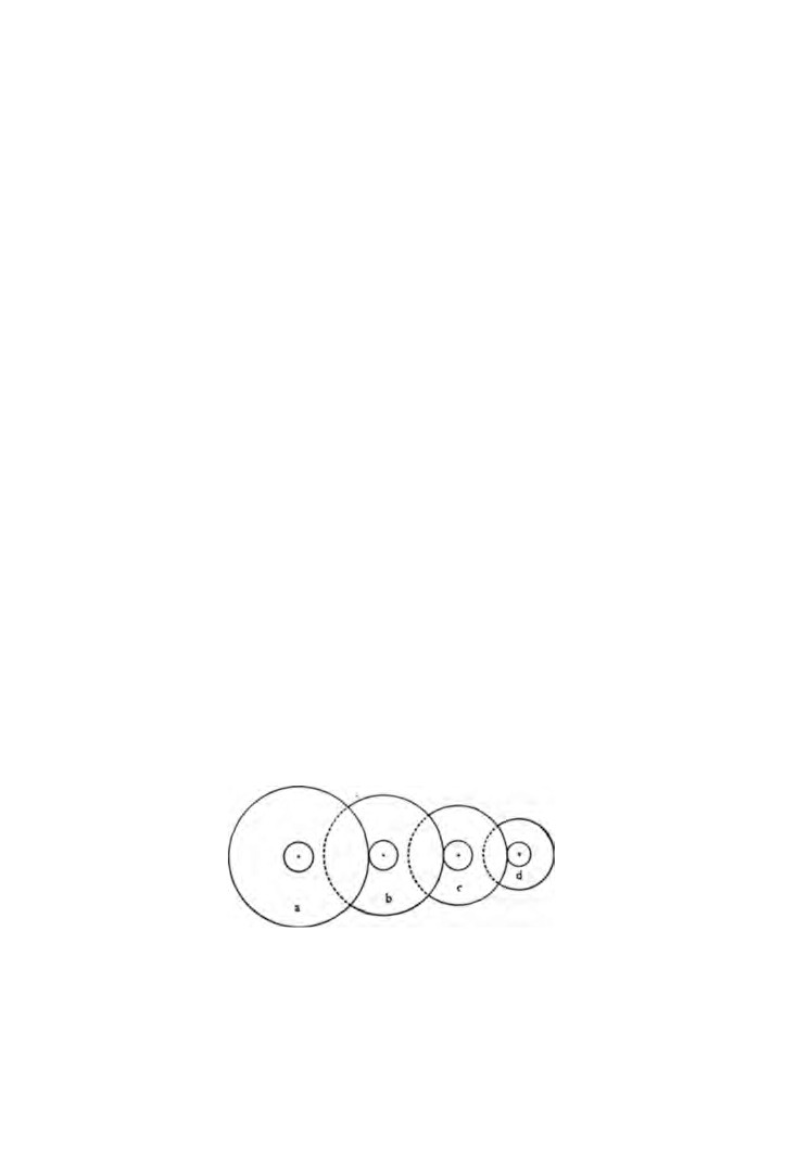
Let us assume the train is as shown in figure 24. Because the
centre wheel has eight times as many teeth as the pinion of the
third wheel it follows that one revolution of the centre wheel
causes the third wheel to rotate eight times.
Following on from this, if the third wheel has 75 teeth and the
fourth wheel pinion
10 leaves, then one revolution of the third
wheel is equal to 7 1/2 revolutions of the fourth wheel.
So far then, we can say that the fourth wheel revolves 8 x 7 1/2 =
60 times to one revolution of the centre wheel.
Finally we come to the escape wheel. The escape wheel pinion
has 8 leaves and is driven by the fourth wheel that has
80 teeth.
One revolution of the fourth wheel will therefore cause the escape
wheel to revolve
10 times.
Fig. 24. Wheel train: (a) centre wheel 80 teeth (b) 3rd wheel 75 teeth,
pinion 10 leaves (c) 4th wheel 80 teeth, pinion 10 leaves (d) escape wheel
80 teeth, pinion 8 leaves.
57

58
WATCH AND CLOCK REPAIRS
Progressive calculations now show that one revolution of the
centre wheel is equal to 8 χ 7 1/2 χ 10 = 600 revolutions of the
escape wheel.
If there are 15 teeth on the escape wheel, and each tooth is
equal to two vibrations of the balance wheel, then the total
Fig.
25. Fitting new tooth.
number of vibrations to one revolution of the centre wheel is
8 χ 7 1/2 χ 10 x 15 χ 2 = 18,000.
This is more simply expressed as
80 χ 75 χ 80 χ (15 χ 2)
= 18,000
10 χ 10 χ 8
If the number of teeth and leaves on the wheels and pinions
are recorded when a watch is dismantled, and the number of
vibrations each hour calculated, adjustments for correct timing
can be made when the movement has been assembled.
In the example given, 18,000 vibrations were made in one hour
= 300 in one minute or 100 in twenty seconds.
Providing a watch that maintains accurate time is available and
fitted with a seconds hand, the beats of the watch undergoing
overhaul can be counted during a period of twenty seconds and
adjustments made as necessary.
WHEEL TRAINS
59
Sometimes inspection of the movement reveals a broken wheel
tooth.
Broken teeth are not common failures but when they do occur
it means a repair or a new wheel. Because of this an attempt at a
repair will be good practice and if the completed job is not good
enough nothing has been lost; a replacement wheel can still be
obtained.
The repair sequence is illustrated in figure
25. The broken
tooth is shown at
(a). With a thin file cut a slot as at
(b). The
teeth on one edge of the file can be ground off to assist in filing
the corners of the slot square.
A piece of brass pin-wire is selected and two flats are filed
opposite each other until the wire fits tightly into the slot as at
(c). Cut off the surplus wire and make sure the remainder is
parallel to the face of the wheel.
Carefully raise the temperature of the wheel in the repair area
by touching it against a soldering iron and then apply some
soldering flux. When the wheel is hot enough place a small piece
of solder on the base of the new tooth and allow the solder to
penetrate through the join to the under-face of the wheel.
Allow to cool off and then file the tooth to shape as at id).
After the repair make sure that all traces of soldering flux and
filings have been washed and brushed away.
CHAPTER SEVEN
Hands, dial and motion work
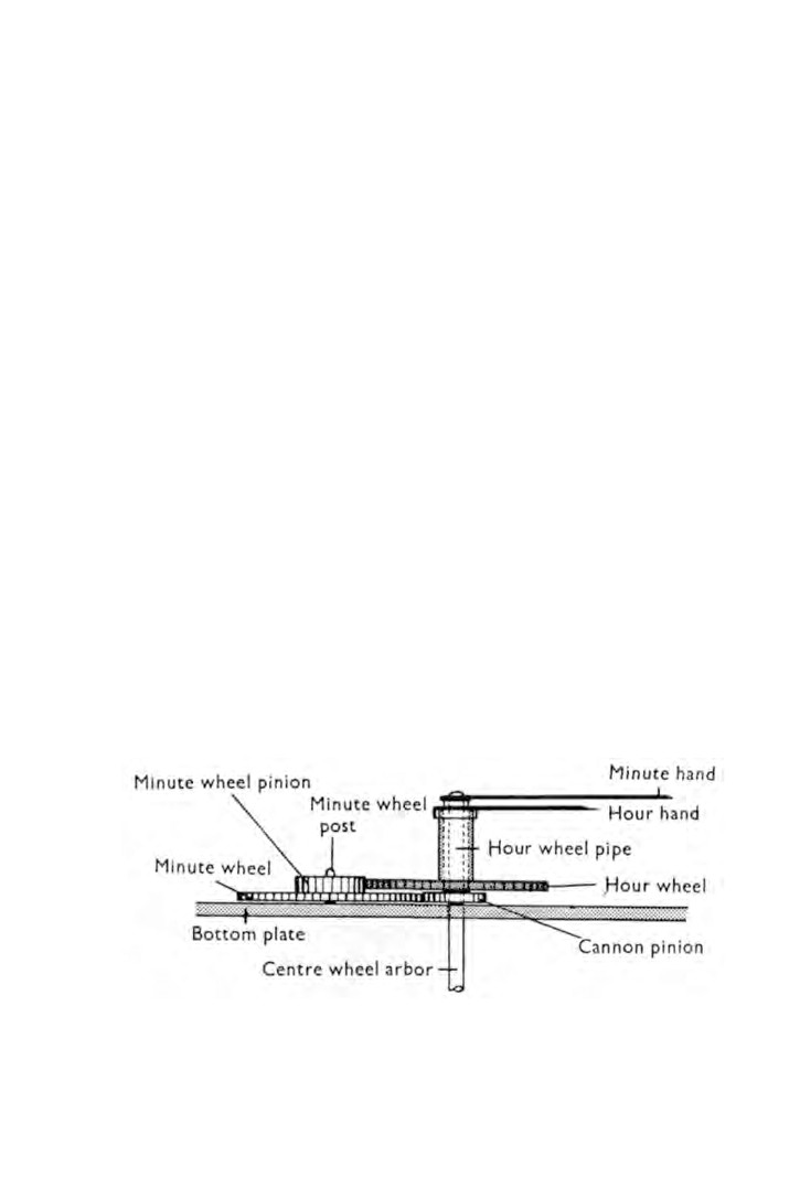
THE motion work consists of a steel cannon pinion, a brass hour
wheel and a brass minute wheel and pinion
(Fig.
26).
The cannon pinion has a groove machined round it and the
base of the groove is burnished inward causing a bulge. The
centre wheel arbor has a corresponding groove cut round it and
when the pinion is pushed on to the arbor the internal bulge snaps
into the arbor groove and provides a friction tight fit.
The minute wheel and pinion revolve on the minute wheel post
which is fixed to the bottom plate.
The cannon pinion drives the minute wheel and the minute
wheel pinion drives the hour wheel which revolves freely around
the cannon pinion.
The hour hand is pushed on to the end of the hour wheel pipe
and the minute hand is fitted over the end of the cannon pinion.
The gear ratios are such that the hour wheel revolves once to
every twelve revolutions of the cannon pinion.
By applying the formula in Chapter
6 for calculating gear
ratios we find :
Fig. 26. Motion work.
60
HANDS, DIAL AND MOTION WORK
6 1
Minute wheel teeth x Hour wheel teeth
= 12
Minute wheel pinion leaves χ Cannon pinion leaves
The most usual wheel trains employed in motion work are
shown in the following table.
Keyless Genevas and
Modern Keyless
Key-wind watches
English Levers
Cannon Pinion
10
8
10
12
14
Minute Wheel
30
32
40
48
28
Minute Pinion
8
10
12
14
8
Hour Wheel
32
30
36
42
48
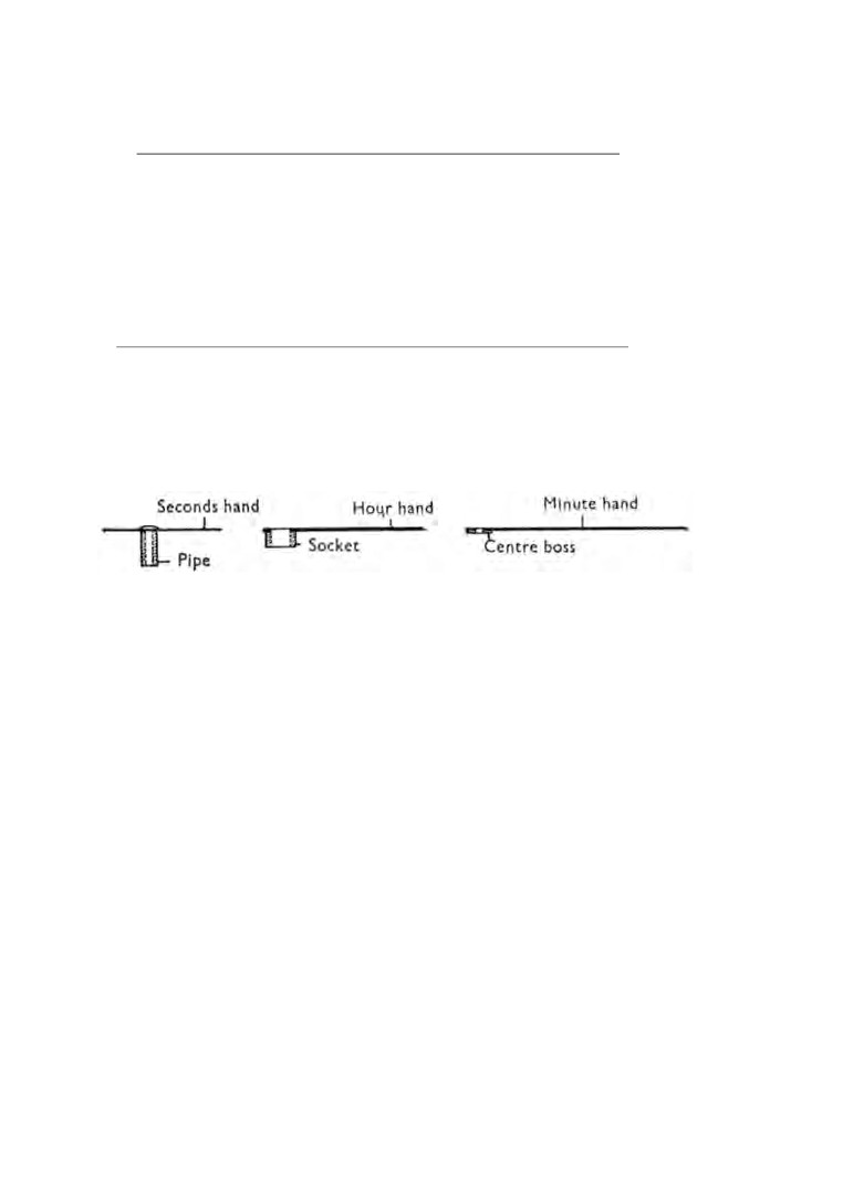
Fig. 27. Hands.
MOTION WORK TRAINS
Hands
(Fig.
27). All too often the fitting of hands receives
insufficient attention. Badly fitted hands are a common cause of
watch failure. They can cause a watch to function intermittently
or to s t o p completely. If a wat ch with a loose-fitting h a n d is
subjected to slight shock, the hand can swing into a new position
and register incorrectly.
A careful functional e x a m i n a t i o n of the h a n d s before dis
mantling will frequently reveal the cause of the trouble. Once the
hands have been removed the evidence is destroyed. This inspec
tion is dealt with fully in Chapter
5 a n d so we will c o nc e r n our
selves here with the correct fitting of replacement hands.
Seconds hand. To fit a new seconds hand to its pivot the pipe
must be broached. This is done by holding the pipe in a pair of
62
WATCH AND CLOCK REPAIRS
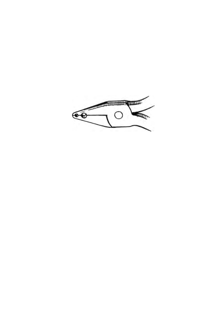
hand-tongs (Fig. 28), and enlarging the hole with a pivot broach.
Only the lightest pressure is needed whilst rotating the broach
between finger and thumb.
To reduce the length of a pipe, drill a hole in a strip of brass
just large enough to allow the pipe to pass through. Place the
hand on the filing block, pipe uppermost, and lower the brass
strip over it. The exposed end of the pipe can now be filed.
The internal burr is removed by using the broach as before.
Fig. 28. Hand-tongs.
The external burr can be taken off by leaving the hand on the
broach and using a pivot file as for pin-filing.
(Chapter
1.)
The outside diameter of the pipe is reduced by using the same
pin-filing technique.
Hour hand. The socket of the hour hand should be a push fit
over the pipe of the hour wheel. To enlarge the socket hole do
not use a broach because this method produces burrs. The socket
is held in the hand-tongs and the hole enlarged by a rat-tail file.
Alternatively, the diameter of the hour wheel pipe can be reduced
in the turns. If when this is done the hour wheel pipe is found to
be gripping the cannon pinion, the hour wheel pipe must be
lightly broached with the hour hand in position.
It may be found that the outside diameter of the hour hand
socket is too great to clear the hole in the dial. In this event the
socket should be reduced in the turns.
Minute hand. Cannon pinions are either square-ended or
round-ended, and the hole in the minute hand centre boss must
be the same. To fit a minute hand to a square ended cannon
HANDS, DIAL AND MOTION WORK
63
pinion a square file is used to enlarge the hole of the centre boss.
The file is used in the corners of the square hole and not on the
sides, making one stroke in each corner at a time. This will assist
in maintaining the square shape.
To enlarge a round hole, use a rat-tail file rather than a broach.
If the thickness of the centre boss needs to be reduced this can
be done by careful filing, but a more satisfactory way is in the
turns.
When opening out the holes of the hour hand and minute hand,
care must be taken to keep the hole square with the hand, and not
to remove too much metal. The finished result should be a push
fit. In the case of the seconds hand the very lightest nip of the
pipe on the pivot is sufficient.
Enamel dials. Due to the fragile nature of the layer of enamel,
these dials must be treated with care. If the enamel is cracked, it
is best left alone. Small pieces can be put back in position by
using glue. If a small piece is missing the space can be filled in
with dial enamel. The cement is warmed and run on to the dial
base and allowed to set. The cement is then filed down to the level
of the surrounding enamel. Hold the dial by one of the feet in a
pair of pliers and pass the dial through a spirit flame. This will
momentarily melt the cement which will set with a glossy
surface.
To enlarge a dial hole a cone-shaped emery stick is used first
to produce a chamfer. These emery sticks are made specially for
this purpose and can be obtained from your supplier. The hole
is then made larger by filing with a rat-tail file moistened with
turpentine.
A broken foot can be replaced. The enamel at the back of the
dial is removed from the affected area by scraping with a sharp
pointed tool. A new foot is made from a length of copper wire and
is silver-soldered to a small disc of copper a little larger in
diameter than the wire. The new foot is now soft-soldered into
position. Marks or discolouration are best removed with warm
soapy water.
Gold and silver dials. These dials are very delicate and should
Components
Screws
100
Plate
5105
Barrel bridge (cheesehead,
105
Barrel bridge
polished)
110
Train wheel bridge
5110
Train wheel bridge (cheese-
121
Balance cock
head, polished)
125
Pallet cock
5121
Balance cock (cheesehead,
180
Barrel complete with arbor
polished)
182
Barrel and cover
5125
Pallet cock,
(cheesehead,
185
Barrel
polished)
190
Barrel cover
5311
Top balance endpiece
195
Barrel arbor
(countersunk, polished
201
Centre wheel complete
ends)
210
Third wheel complete
5330
Bottom balance endpiece
220
Fourth wheel complete
(countersunk, polished
240
Cannon pinion
ends)
250
Hour wheel
5415
Barrel ratchet
260
Minute wheel
5420
Top crown wheel
(trans
301
Regulator index
mission wheel)(lefthand)
311
Top balance endpiece
5425
Click
330
Bottom balance endpiece
5443
Setting bolt (pull-out piece)
401
Winding stem
5445
Setting bolt spring
(pull-
407
Castle wheel
out piece spring)
410
Winding pinion (crown
5721
Balance
wheel)
5738
Hairspring stud
415
Barrel ratchet
5750
Dial edge
420
Top crown wheel
(trans
mission wheel)
422
Crown wheel collar
425
Click
Jewels
430
Click spring
630
Top balance
435
Return bar
631
Bottom balance
440
Return bar spring
615
Escape top
443
Setting bolt (pull-out piece)
616
Escape bottom
445
Setting bolt spring (pull-out
620
Top pallet
piece spring)
621
Bottom pallet
450
Intermediate wheel
646
Entry pallet
705
Escape wheel complete
647
Exit pallet
710
Pallets complete
610
Top fourth
721
Balance complete
611
Bottom fourth
723
Balance staff
605
Top third
730
Roller
606
Bottom third
734
Hairspring complete
601
Top centre
738
Hairspring stud
602
Bottom centre
770
Mainspring
648
Roller (impulse pin)
KEY TO PLATE 1
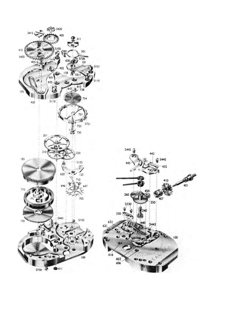
Plate I: 5 1/4 χ 8 3/4 ligne 15-jewel lever movement (see facing page).
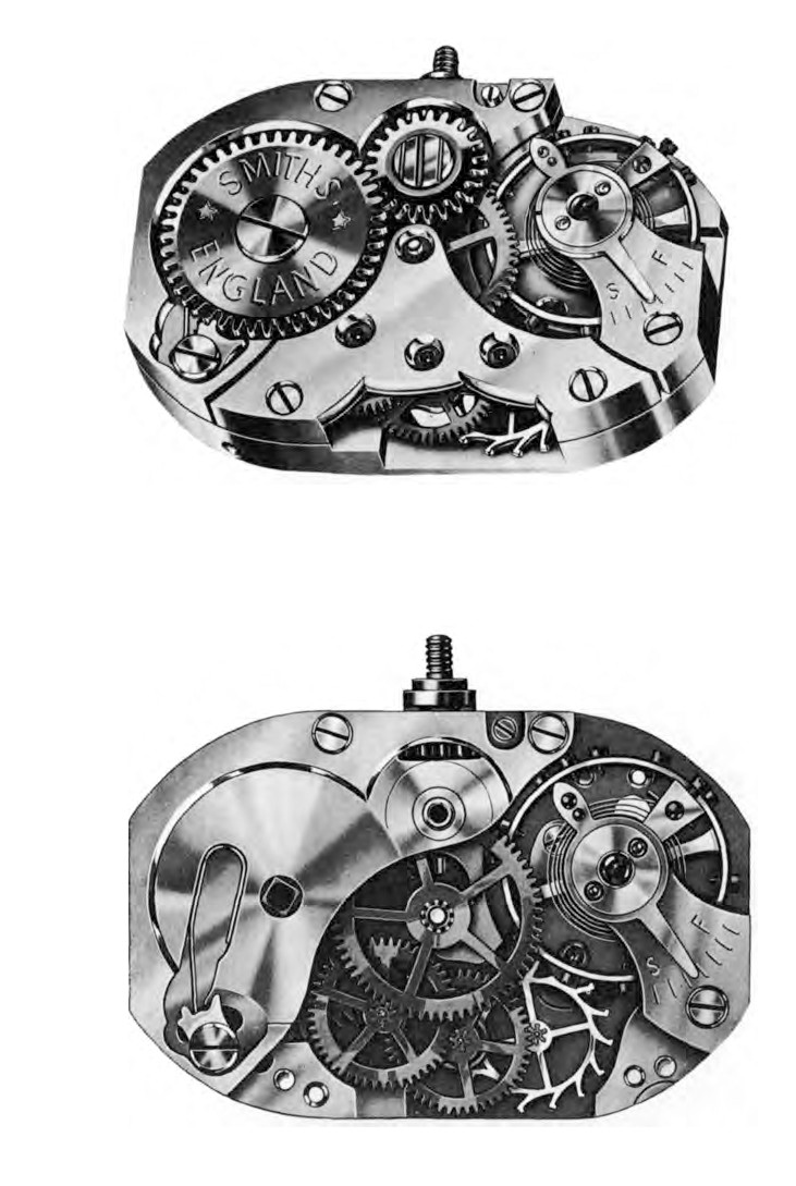
Plate II: 5 1/4 χ 8 3/4 ligne movement.
Plate III: Train wheel bridge removed.
HANDS, DIAL AND MOTION WORK
65
be handled in soft tissue paper. Finger marks can be removed
from gold dials by light rubbing with tissue paper. Silver dials
discolour badly with age. Both types of dials may be washed in
warm soapy water and dried in boxwood dust. They should never
be brushed or rubbed with a cloth.
Broken feet can be replaced by soft-soldering a length of copper
wire into position.
Filing is the only method of enlarging holes. A rat-tail file is
used inserted from the face side.
CHAPTER EIGHT
Keyless work
KEYLESS work as the name implies is a method of winding the
mainspring without the use of a key.
There are a few ways in which this is done but we will consider
the method most used in wristwatches.
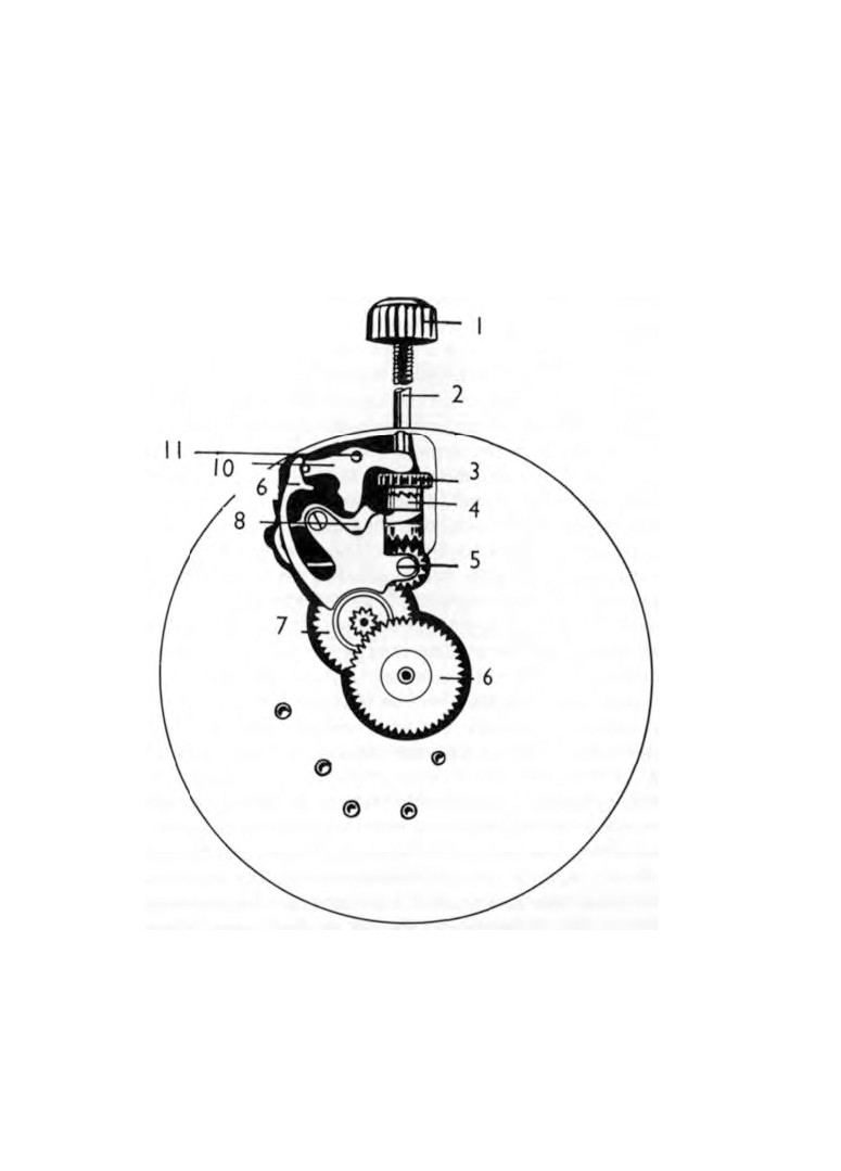
Figure
29 shows a typical arrangement of keyless work. The
winding stem is threaded at one end for the winding button. At
the base of the threaded portion is a shoulder that works in the
movement plate. Beneath this shoulder a groove is cut to receive
the pin of the pull-out piece, and beneath the groove is another
shoulder that locates the crown wheel. The remaining length is
squared to take the castle wheel with the exception of the end
which is turned down to form a pivot.
The pull-out piece is retained in position by a shouldered
screw. The crown wheel rotates on the lower shoulder of the
winding stem. The castle wheel has a square hole and although free
to slide up and down the squared portion of the winding stem
must nevertheless rotate with it. The check-spring is held in
position at one end by a screw, and the other end is positioned in
the groove of the castle wheel. The upper face of the castle wheel
and the lower face of the crown wheel are cut with identically
shaped ratchet teeth and are in mesh with each other. The upper
edge of the crown wheel is cut with gear teeth which mesh with
the transmission wheel. The bottom face of the castle wheel is
cut with gear teeth and can be meshed with the intermediate
wheel.
The normal position for this mechanism is as shown in figure
29. Turning the winding button and stem will cause the castle
wheel to rotate. Because the check-spring is holding the castle
wheel in mesh with the crown wheel the crown wheel must
rotate as well.
In turning the crown wheel, the transmission wheel on the top
66
KEYLESS WORK
67
plate is rotated which, through the ratchet wheel, causes the
mainspring to be wound.
If a sharp pull is given to the winding stem, the pull-out piece
will turn with its screw causing the check-spring to be pressed
downward. This position is maintained by the end of the pull-out
piece dropping into a step cut in the edge of the check-spring.
Fig. 29. Keyless work. 1. Winding button. 2. Winding stem. 3. Crown
wheel. 4. Castle wheel. 5. Intermediate wheel. 6. Hour wheel. 7. Minute
wheel. 8. Return bar. 9. Check spring. 10. Pull-out piece. 11. Pull-out
piece screw.