Boeing 737 - 600/700/800/900. Operations Manual (1997 year) - page 24
Airplane General, Emergency
Equipment, Doors, Windows -
Systems Description
Boeing 737 Operations Manual
Taxi Lights
The taxi light is mounted on the nose wheel strut and points in the same direction
as the nose wheel.
Logo Lights
Logo lights are located on the top of each horizontal stabilizer surface to point
light on both sides of the vertical stabilizer.
Position Lights
The navigation lights are the standard red (left forward wingtip), green (right
forward wingtip), and white (aft tip of both wings) position lights.
Strobe Lights
Three high intensity white strobe lights are installed on the left forward wing tip,
right forward wing tip, and tail cone.
Anti-collision Lights
Two red anti-collision strobe lights are located on the top and bottom of the
fuselage.
Wing Illumination Lights
Wing lights are installed on the fuselage and illuminate the leading edge of the
wing.
Wheel Well Lights
Lights are installed in the wheel well of the nose gear and each main gear.
1.40.2
Airplane General, Emergency
Equipment, Doors, Windows -
Systems Description
Boeing 737 Operations Manual
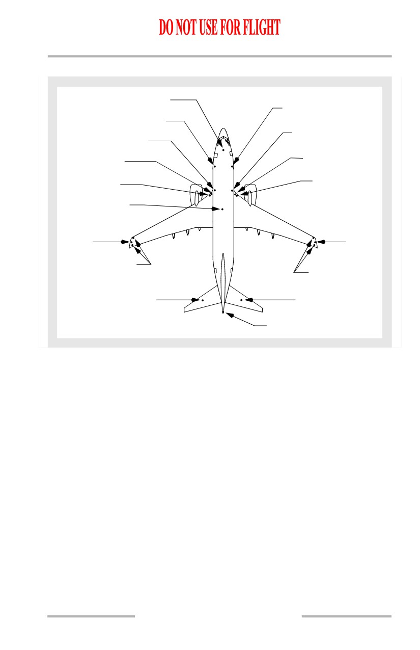
Exterior Lighting Locations
TAXI LIGHT
(white,nose gear)
WING ILLUMINATION
LIGHTS (white)
WING ILLUMINATION
LIGHTS (white)
RETRACTABLE LANDING
RETRACTABLE LANDING
LIGHTS
(white)
LIGHTS
(white)
RUNWAY TURNOFF
RUNWAY TURNOFF
LIGHTS (white)
LIGHTS (white)
FIXED LANDING
FIXED LANDING
LIGHTS (white)
LIGHTS (white)
UPPER AND LOWER
ANTI-COLLISION LIGHT
(red strobe light)
STROBE
STROBE
LIGHT (white)
LIGHT
(white)
POSITION LIGHTS
(red and white)
POSITION LIGHTS
(green and white)
LOGO LIGHT (white)
LOGO LIGHT (white)
STROBE LIGHT (white)
1.40.3
Airplane General, Emergency
Equipment, Doors, Windows -
Systems Description
Boeing 737 Operations Manual
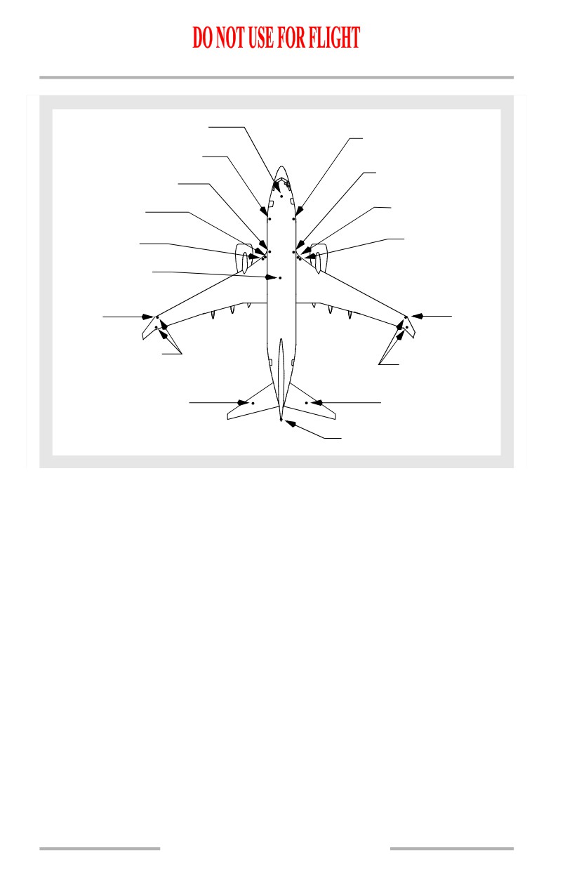
[Option: Winglets]
TAXI LIGHT
(white,nose gear)
WING ILLUMINATION
LIGHTS (white)
WING ILLUMINATION
LIGHTS (white)
RETRACTABLE LANDING
RETRACTABLE LANDING
LIGHTS
(white)
LIGHTS
(white)
RUNWAY TURNOFF
RUNWAY TURNOFF
LIGHTS (white)
LIGHTS (white)
FIXED LANDING
FIXED LANDING
LIGHTS (white)
LIGHTS (white)
UPPER AND LOWER
ANTI-COLLISION LIGHT
(red strobe light)
STROBE
STROBE
LIGHT (white)
LIGHT
(white)
POSITION LIGHTS
(red and white)
POSITION LIGHTS
(green and white)
LOGO LIGHT (white)
LOGO LIGHT (white)
STROBE LIGHT (white)
Flight Deck Lighting
Flight deck lighting is provided for panel illumination, area lighting and localized
illumination. Dome lights supply general flight deck flood lighting. The
glareshield supplies background light for the main instrument panels. Each
instrument and instrument panel has its own integral lights. Floodlights are
installed for the MCP, aisle stand, and aft circuit breaker panel.
Map lights, chart lights and utility lights are available at the pilot stations, each
with individual controls.
If normal electrical power is lost, standby electrical power is automatically
provided to the standby compass light, dome lights, instrument flood lights and
selected system information and warning lights.
Passenger Cabin Lighting
Passenger cabin lighting is supplied by incandescent and fluorescent lights.
General cabin lighting is provided by window lights, ceiling lights, and entry
lights. Reading lights are located above each passenger seat in the passenger
service unit. Lights are also installed in the lavatories and galleys.
1.40.4
Airplane General, Emergency
Equipment, Doors, Windows -
Systems Description
Boeing 737 Operations Manual
Passenger Cabin Signs
The passenger cabin signs are controlled by a switch on the forward overhead
panel. With Auto selected, the signs are controlled automatically by reference to
landing gear and flap positions:
FASTEN BELTS and RETURN TO SEAT signs:
• illuminate when flaps or gear are extended
• extinguish when flaps and gear are retracted.
NO SMOKING signs:
• illuminate when gear is extended
• extinguish when gear is retracted.
All passenger signs can be controlled manually by positioning the respective
switch to ON or OFF.
When the passenger cabin signs illuminate or extinguish, a low tone sounds over
the PA system.
Emergency Lighting
Exit lights are located throughout the passenger cabin to indicate the approved
emergency exit routes. The system is controlled by a switch on the overhead panel.
The switch has three positions, OFF, ARMED and ON and is guarded to the
ARMED position. With the switch in the ARMED position, the emergency exit
lights are normally extinguished. If electrical power to DC bus No. 1 fails or if AC
power has been turned off, the emergency exit lights illuminate automatically.
The emergency exit lights may also be illuminated by a switch on the aft
attendants panel. Lifting the guard and pushing the switch ON overrides the flight
deck control and illuminates the emergency exit lights. Control from this panel is
available in the event of failure of the automatic control.
The flight deck aft DOME light contains a separate bulb that is powered by the
emergency lighting system to provide for flight deck evacuation.
Interior Emergency Lighting
Interior emergency exit lights are located:
• in the lower inboard corner of stowage bins to illuminate the aisle
• over the entry/service and overwing emergency hatches to indicate the
door and hatch exits
• in the ceiling to locate the exits and provide general illumination in the
area of the exits.
Self-illuminating exit locator signs are installed at the forward, middle, and aft
end of the passenger cabin.
1.40.5
Airplane General, Emergency
Equipment, Doors, Windows -
Systems Description
Boeing 737 Operations Manual
Floor proximity emergency escape path lighting consists of locator lights spaced
at regular intervals down one side of the aisle. Lighted arrows point to overwing
exits and a lighted EXIT indicator is near the floor by each door and overwing exit.
Escape path markings are provided for visual guidance for emergency cabin
evacuation when other sources of cabin lighting are obscured.
Interior Emergency Lighting
[Option: Photoluminescent Lighting System]
Interior emergency exit lights are located:
• in the lower inboard corner of stowage bins to illuminate the aisle
• over the entry/service and overwing emergency hatches to indicate the
door and hatch exits
• in the ceiling to locate the exits and provide general illumination in the
area of the exits.
Self-illuminating exit locator signs are installed at the forward, middle, and aft
end of the passenger cabin.
A photoluminescent floor path marking system is installed along the cabin aisle.
The photoluminescent material, when excited by light, will glow and provide exit
path guidance. At the exit, electrically operated lights and markers provide exit
identification.
The photoluminescent strips need to be properly charged. The table below
contains charging information and can be used to determine how long the strips
remain illuminated. For charging, the cabin ceiling, and sidewall lights need to be
on at full intensity, and the strips should not be covered or blocked.
1.40.6
Airplane General, Emergency
Equipment, Doors, Windows -
Systems Description
Boeing 737 Operations Manual
Charge Scenario
Photoluminescent
Remarks
Duration (Hours)
First flight of the day - bins
closed, no passengers
•
5 minute charge
•
4.25
Close overhead bins during
•
10 minute charge
•
8
charging and cabin activity is
limited to minor aisle traffic of
•
15 minute charge
•
9.5
crew and personnel. Passengers
•
30 minute charge
•
14
will shadow the system and are
•
45 minute charge
•
16
not allowed on board during
charging.
First flight of the day - bins
open, no passengers
•
15 minute charge
•
5.75
Cabin activity is limited to minor
•
30 minute charge
•
7.5
aisle traffic of crew and personnel.
Passengers will shadow the
system and are not allowed on
board during charging.
Photoluminescent duration can be extended beyond the initial charge, by using the
following charge scenarios:
In flight/taxi - with cabin
No limit with
lighting on
ceiling lights on
dim or greater
In flight/taxi - with cabin
lighting off
•
15 minute charge
•
8
Begin charging prior to previous
•
30 minute charge
•
11.25
discharge duration ending.
1.40.7
Airplane General, Emergency
Equipment, Doors, Windows -
Systems Description
Boeing 737 Operations Manual
Charge Scenario
Photoluminescent
Remarks
Duration (Hours)
Ground turn with bin doors
open and passengers in seats
•
15 minute charge
•
6.75
Bin doors can be open during
•
30 minute charge
•
9
charging. Passenger loading and
unloading periods cannot be
included in the charge time.
Passengers can be on the airplane.
Begin charging prior to previous
discharge duration.
Ground turn with bin doors
open and no passengers in
seats
•
15 minute charge
•
7.5
Bin doors can be open during
•
30 minute charge
•
10
charging. Passenger loading and
unloading periods cannot be
included in the charge time.
Passengers cannot be on the
airplane. Begin charging prior to
previous discharge duration.
Exterior Emergency Lighting
Exterior emergency lights illuminate the escape slides. The fuselage installed
escape slide lights are adjacent to the forward and aft service and entry doors.
Lights are also installed on the fuselage to illuminate the overwing escape routes
and ground contact area.
1.40.8
Airplane General, Emergency
Equipment, Doors, Windows -
Systems Description
Boeing 737 Operations Manual
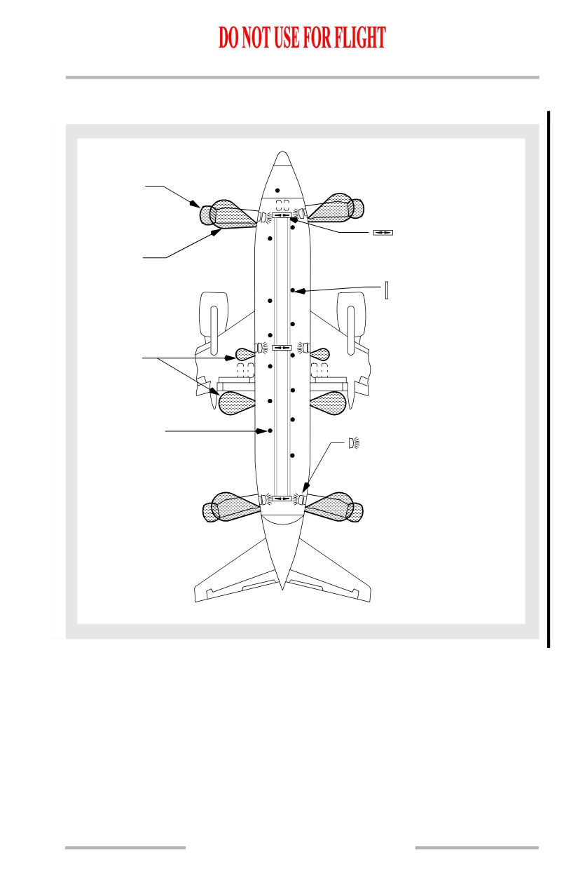
Emergency Exit Lighting
[Option - 737-600/700]
INTEGRAL SLIDE
LIGHTING
EXIT LOCATOR SIGNS
ESCAPE SLIDE
- Located in the
LIGHTING
passenger cabin
ceiling.
PHOTOLUMINESCENT
STRIP LIGHTING
EXTERIOR
EMERGENCY
LIGHTING
AISLE LIGHTS
EMERGENCY EXIT SIGNS
- Located in the forward
and aft lowered ceiling,
in the center of the
passenger cabin above
the overwing escape
hatches, and above each
entry and service door.
1.40.9
Airplane General, Emergency
Equipment, Doors, Windows -
Systems Description
Boeing 737 Operations Manual
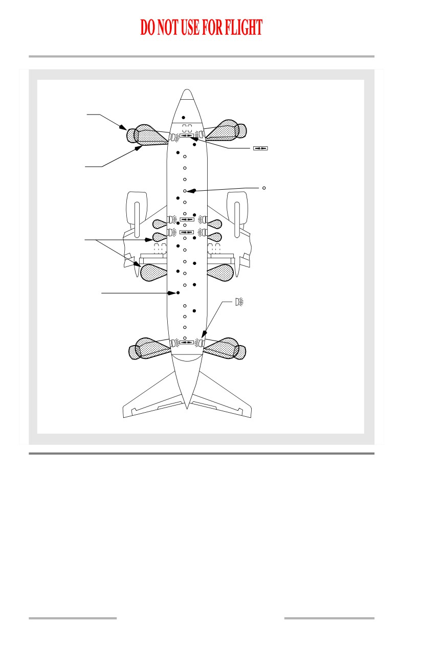
[Option - 737-800/900]
INTEGRAL SLIDE
LIGHTING
EXIT LOCATOR SIGNS
ESCAPE SLIDE
- Located in the
LIGHTING
passenger cabin
ceiling.
FLOOR PROXIMITY
AISLE LOCATOR LIGHTS
EXTERIOR
EMERGENCY
LIGHTING
AISLE LIGHTS
EMERGENCY EXIT SIGNS
- Located in the forward
and aft lowered ceiling,
in the center of the
passenger cabin above
the overwing escape
hatches, and above each
entry and service door.
Oxygen Systems
Two independent oxygen systems are provided, one for the flight crew and one for
the passengers. Portable oxygen cylinders can be located throughout the airplane
for emergency use. These cylinders are normally found in the forward and aft
areas of the passenger cabin.
1.40.10
Airplane General, Emergency
Equipment, Doors, Windows -
Systems Description
Boeing 737 Operations Manual
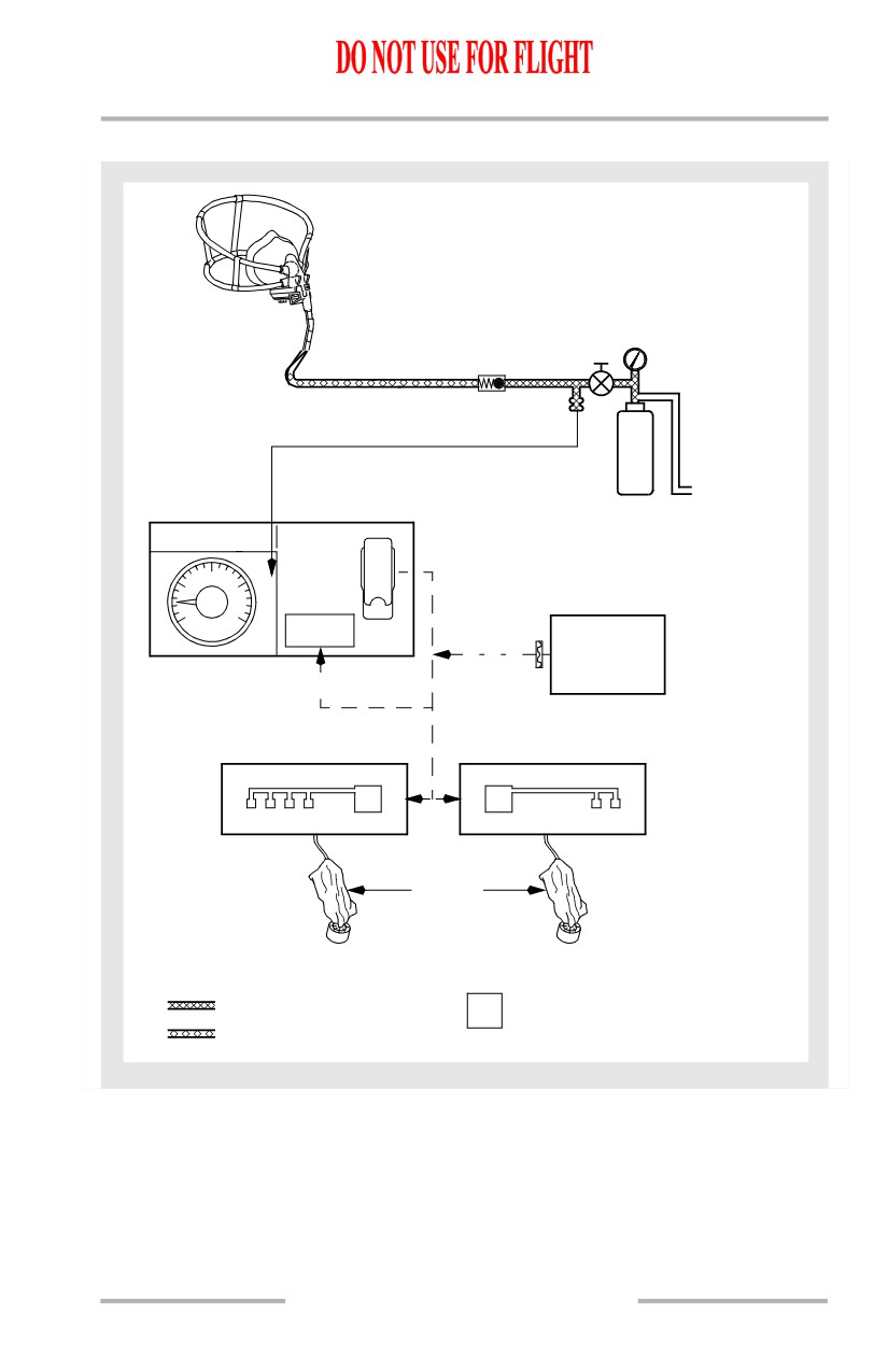
Oxygen System Schematic
OXYGEN MASK
(
TYPICAL
)
PRESSURE
REDUCER
THERMAL
DISCHARGE
PORT
CREW
OXYGEN
CREW
PASS OXYGEN
CYLINDER
OXYGEN
NORMAL
10
5
15
ON
0
20
OXY PRESS
PASS OXY
PS1 X 100
ON
14,000 FT
BAROMETRIC
PRESSURE
SWITCH
PASSENGER SERVICE UNITS
ATTENDANT STATIONS
O2G
O2G
LAVATORIES
SERVICE
(4 MASKS)
UNITS
(2 MASKS)
CONDITION: NORMAL
CHEMICAL OXYGEN GENERATOR
HIGH PRESSURE
O
2G
(IN EACH SERVICE UNIT)
LOW PRESSURE
1.40.11
Airplane General, Emergency
Equipment, Doors, Windows -
Systems Description
Boeing 737 Operations Manual
Flight Crew Oxygen System
The flight crew oxygen system uses quick-donning, diluter-demand masks/
regulators located at each crew station. Oxygen is supplied by a single cylinder.
Oxygen pressure is displayed on the Oxygen Pressure indicator located on the aft
overhead panel when the battery switch is ON. Oxygen flow is controlled through
an in-line, pressure-reducing regulator to supply low-pressure oxygen to the
regulator on the mask. System pressure may be as high as 1850 psi.
Oxygen flow is controlled by a regulator mounted on the oxygen mask. By
pushing the NORMAL/100% control lever, the regulator is adjusted from the
air/oxygen mixture to 100% oxygen. By rotating the EMERGENCY/PUSH TO
TEST selector, the regulator is adjusted to supply oxygen under pressure.
Flight Crew Oxygen Mask Usage
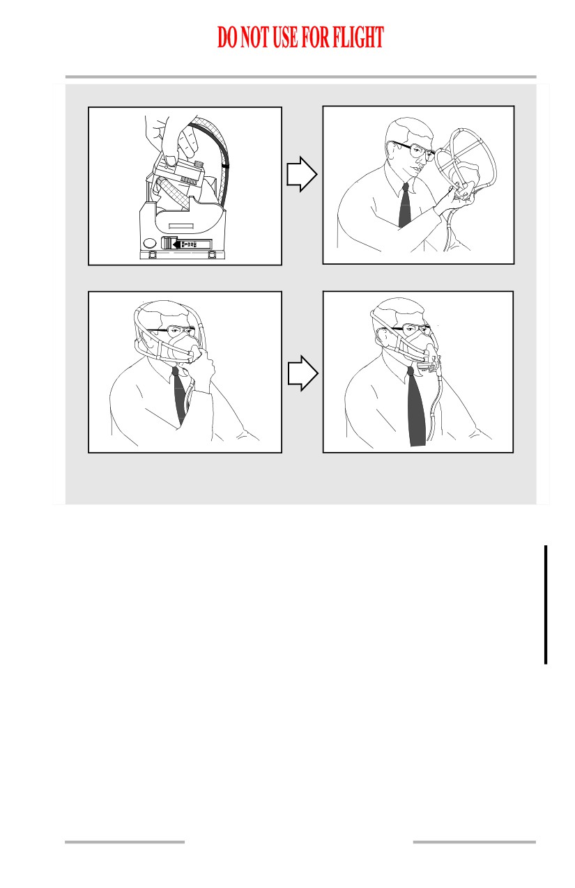
Donning Instructions
To don the mask, grasp the regulator with the thumb and forefinger and remove
from stowage. Squeezing the inflation levers and removing from the box:
• inflates the mask harness
• momentarily displays a colored oxygen flow indicator.
• Place the mask over the head and release the levers. The harness contracts
to fit the mask to head and face.
The observer’s oxygen mask, regulator, and harness unit is the same as the pilots’.
1.40.12
Airplane General, Emergency
Equipment, Doors, Windows -
Systems Description
Boeing 737 Operations Manual
Mask Donning
Portable Protective Breathing Equipment
Protective Breathing Equipment (PBE/Smoke Hood) devices for crew use (for
combating fires and/or entering areas of smoke or fume accumulation) may be
stowed throughout the airplane; however, they are normally found in the forward
and aft sections of the passenger cabin. The device is placed over the head and,
when activated, provides approximately
15 to over 20 minutes of oxygen
depending upon the device used. Manufacturer’s operating instructions are
placarded on the container.
Passenger Oxygen System
The passenger oxygen system is supplied by individual chemical oxygen
generators located at each Passenger Service Unit (PSU). Four continuous flow
masks are connected to each generator. A generator with two masks is located
above each attendant station and in each lavatory.
1.40.13

Airplane General, Emergency
Equipment, Doors, Windows -
Systems Description
Boeing 737 Operations Manual
The system is activated automatically by a pressure switch at a cabin altitude of
14,000 feet or when the Passenger Oxygen Switch on the aft overhead panel is
positioned to ON. When the system is activated, the PASS OXY ON light
illuminates and OVERHEAD illuminates on the Master Caution System.
Activating the system causes the masks to drop from the stowage compartments.
The oxygen generators are activated when any mask in the unit is pulled down.
Pulling one mask down causes all masks in that unit to come down and 100%
oxygen flows to all masks. A green in-line flow indicator is visible in the
transparent oxygen hose whenever oxygen is flowing to the mask. Oxygen flows
for approximately 12 minutes and cannot be shut off. If the passenger oxygen is
activated and a PSU oxygen mask compartment does not open, the masks may be
dropped manually.
PSU Oxygen Mask Compartment
CHEMICAL OXYGEN
GENERATOR
RELEASE FIRING PIN
DOOR LATCH
MECHANISM
GENERATOR LANYARD
OXYGEN MASK LANYARD
FWD
OXYGEN IN-LINE
PSU
FLOW INDICATOR
OXYGEN MASK DOOR
(SHOWN OPEN)
OXYGEN HOSE
RESERVOIR BAG
MASK
WARNING: When using passenger oxygen, the “NO SMOKING” sign
should be strictly observed. Once the generator is activated,
the flow of oxygen is constant, whether or not the mask is
being worn.
WARNING: Do not use passenger oxygen with cabin altitude below 14,000
feet when smoke or an abnormal heat source is present. The
use of passenger oxygen does not prevent the passengers from
inhaling smoke. Air inhaled is a mixture of oxygen and cabin
air.
1.40.14
Airplane General, Emergency
Equipment, Doors, Windows -
Systems Description
Boeing 737 Operations Manual
Passenger Portable Oxygen
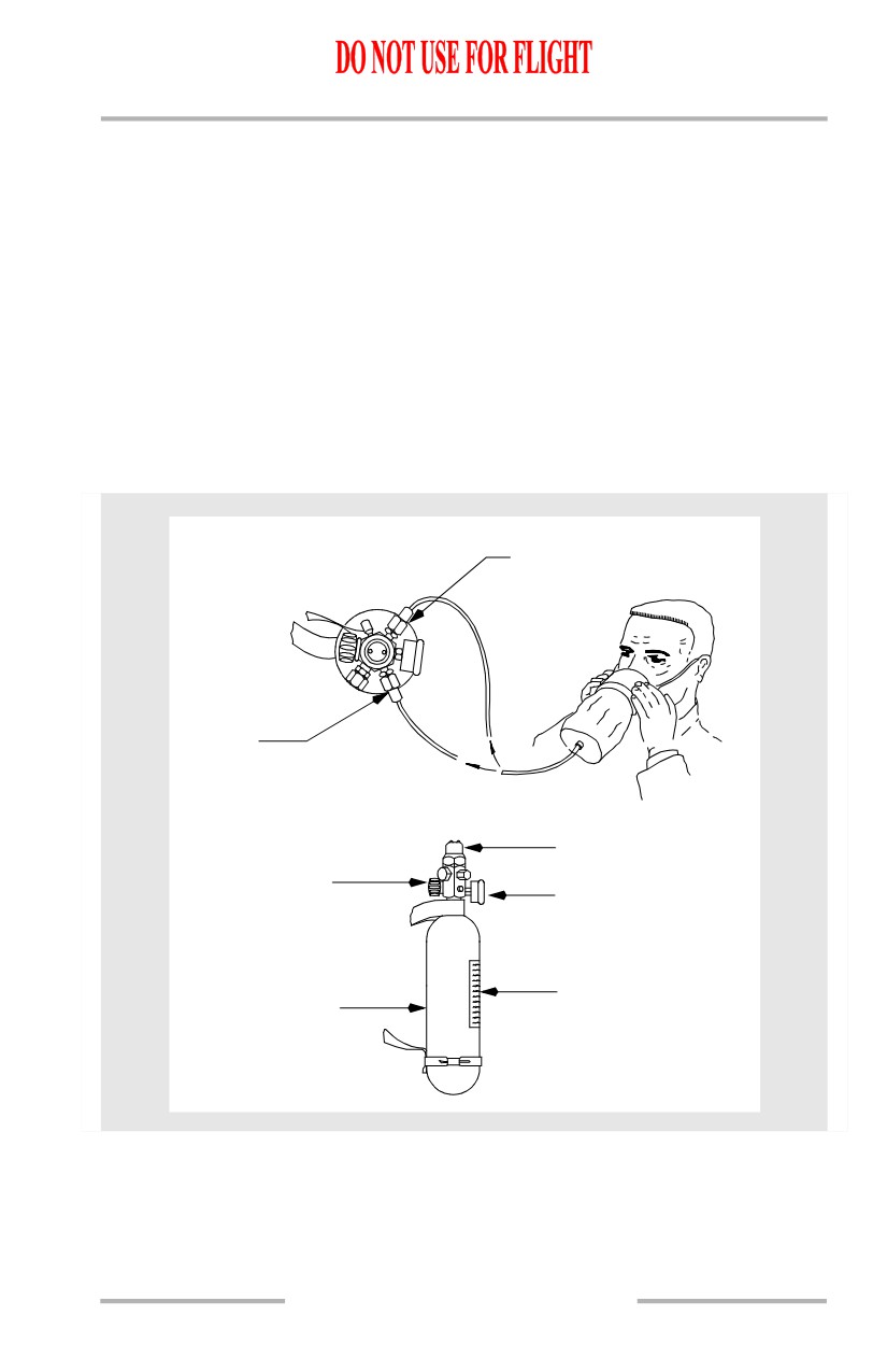
First aid and supplemental portable oxygen cylinders are installed at suitable
locations in the passenger cabin. The cylinders are fitted with a pressure gage,
pressure regulator and on-off valve. The cylinders are pressurized to 1800 psi. At
this pressure and a temperature of 70 degrees Fahrenheit, (21 degrees Celsius) the
cylinders have a capacity of 4.25 cubic feet (120 liters) of free oxygen. Two
continuous flow outlets are provided on each cylinder, one regulates flow at two
liters per minute for walk-around; the second outlet provides flow at four liters per
minute. The four-liter flow is used for first aid.
Duration can be determined by dividing capacity by outflow (120 liters divided by
4 liters/minute = 30 minutes).
Passenger Portable Oxygen Schematic
CONSTANT FLOW
OUTLET (4 LITER FLOW)
CONSTANT
FLOW
OUTLET
(2 LITER
FLOW)
PRESSURE REGULATOR
ON-OFF VALVE
PRESSURE GAUGE
PLACARD
OXYGEN CYLINDER
1.40.15
Airplane General, Emergency
Equipment, Doors, Windows -
Systems Description
Boeing 737 Operations Manual
Fire Extinguishers
Fire extinguishers are located in the flight deck and passenger cabin.
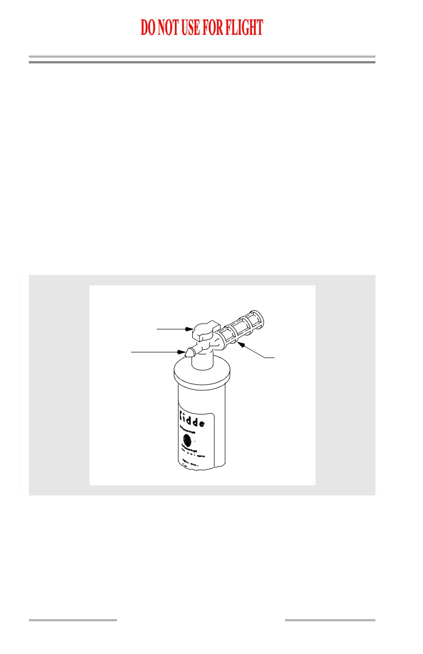
Water Fire Extinguishers
Water fire extinguishers contain a solution of water mixed with antifreeze. The
container is pressurized by a CO2 cartridge when the extinguisher handle is
rotated fully clockwise. The extinguisher should be used on fabric, paper or wood
fires only.
To use the water fire extinguisher:
• remove from stowage
• rotate handle fully clockwise
• aim at base of fire and press trigger.
CAUTION: Do not use on electrical or grease type fires.
Water Fire Extinguisher
TRIGGER
SAFETY WIRED
DISCHARGE
NOZZLE
HANDLE
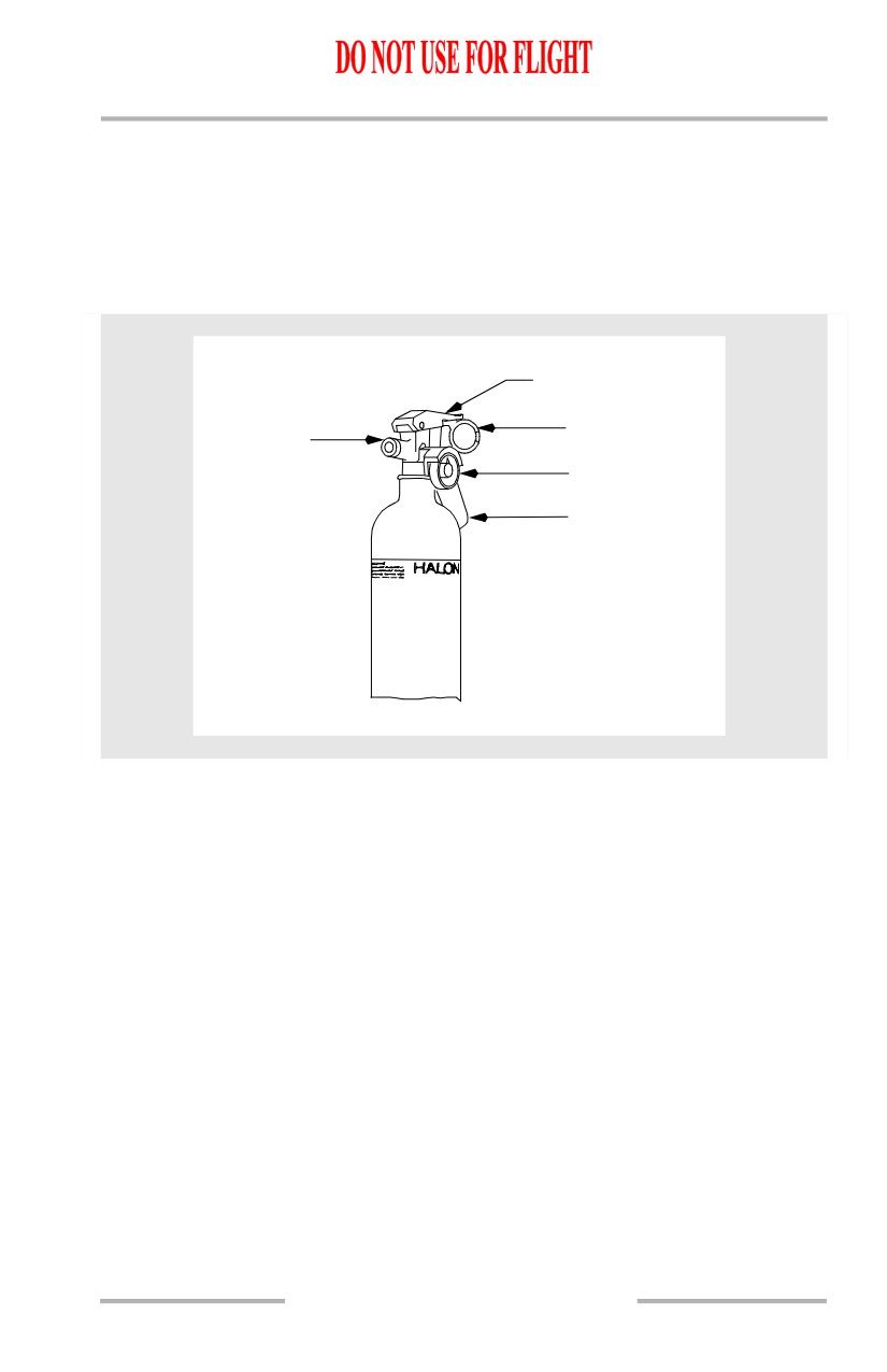
Halon (BCF) Fire Extinguishers
Halon (BCF) fire extinguishers contain a liquefied gas agent under pressure. The
pressure indicator shows an acceptable pressure range, a recharge range, and an
overcharged range. A safety pin with a pull ring prevents accidental trigger
movement. When released the liquefied gas agent vaporizes and extinguishes the
fire. The extinguisher is effective on all types of fires, but primarily on electrical,
fuel and grease fires.
1.40.16
Airplane General, Emergency
Equipment, Doors, Windows -
Systems Description
Boeing 737 Operations Manual
To use the Halon fire extinguisher:
• remove from stowage
• hold upright and remove ringed safety pin
• aim at base of fire from a distance of six feet and press top lever
• use side to side motion to suppress fire.
BCF Fire Extinguisher (Halon 1211)
LEVER
DISCHARGE
RING SAFETY
NOZZLE
PIN
PRESSURE
GAUGE
HANDLE
1.40.17
Airplane General, Emergency
Equipment, Doors, Windows -
Systems Description
Boeing 737 Operations Manual
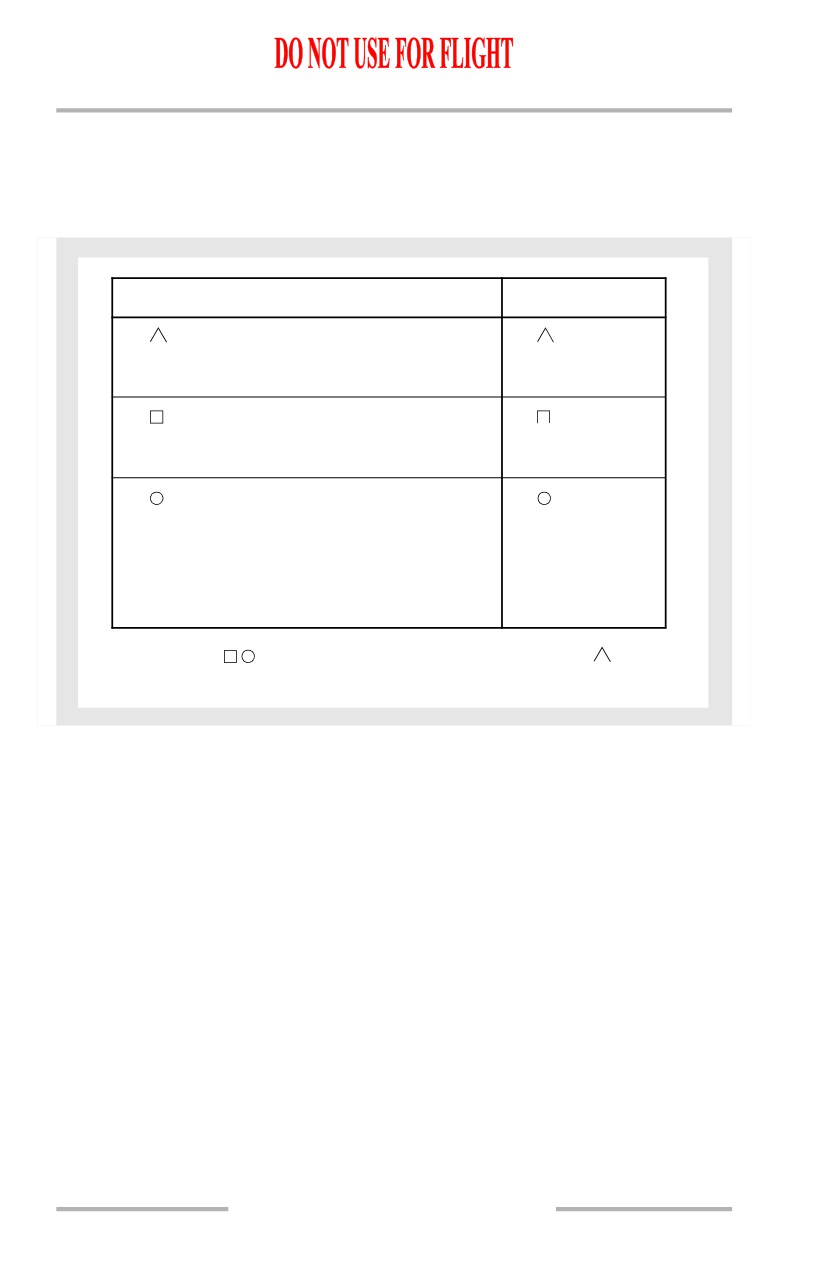
Fire Extinguisher Usage
Each class of fire calls for specialized action. Using the wrong extinguisher may
do more harm than good. For your own protection, you should know these basic
types, how to use them, and why.
CLASS OF FIRES
EXTINGUISHER TYPE
There are three common classes of fire:
CLASS
A
COMBUSTABLE - paper, wood, fabric, rubber,
TYPE
A
MATERIALS
certain plastics, etc., where
Water (H2O) saturates
quenching by water is effective.
material and prevents
rekindling.
CLASS
B
FLAMMABLE
- gasoline, oils, greases, solvents,
TYPE B
LIQUIDS
paints, burning liquids, cooking
BCF (Halon 1211)
fats, etc., where smothering
action is required.
CLASS
C
LIVE
- fires started by short circuit or
TYPE C
ELECTRICAL
faulty wiring in electrical,
BCF (Halon 1211)
electronic equipment, or fires in
motors, switches, galley equipment,
etc., where a nonconducting
extinguisher agent is required.
NOTE: Whenever possible, electrical
equipment should be de-energized
before attacking a class C fire.
WARNING: THE WRONG EXTINGUISHER ON A FIRE COULD DO MORE HARM THAN GOOD. FOR
EXAMPLE,
B
C
RATED EXTINGUISHER IS NOT AS EFFECTIVE AS H2O ON A CLASS
A
FIRE. WATER ON FLAMMABLE LIQUID FIRES SPREAD THE FIRE. WATER ON A LIVE
ELECTRICAL FIRE COULD CAUSE SEVERE SHOCK OR DEATH.
WARNING: The concentrated agent, or the by-products created by the heat
of the fire, are toxic when inhaled.
WARNING: If a fire extinguisher is to be discharged in the flight deck, then
all crewmembers are to wear oxygen masks and use 100%
oxygen with emergency selected.
1.40.18
Airplane General, Emergency
Equipment, Doors, Windows -
Systems Description
Boeing 737 Operations Manual
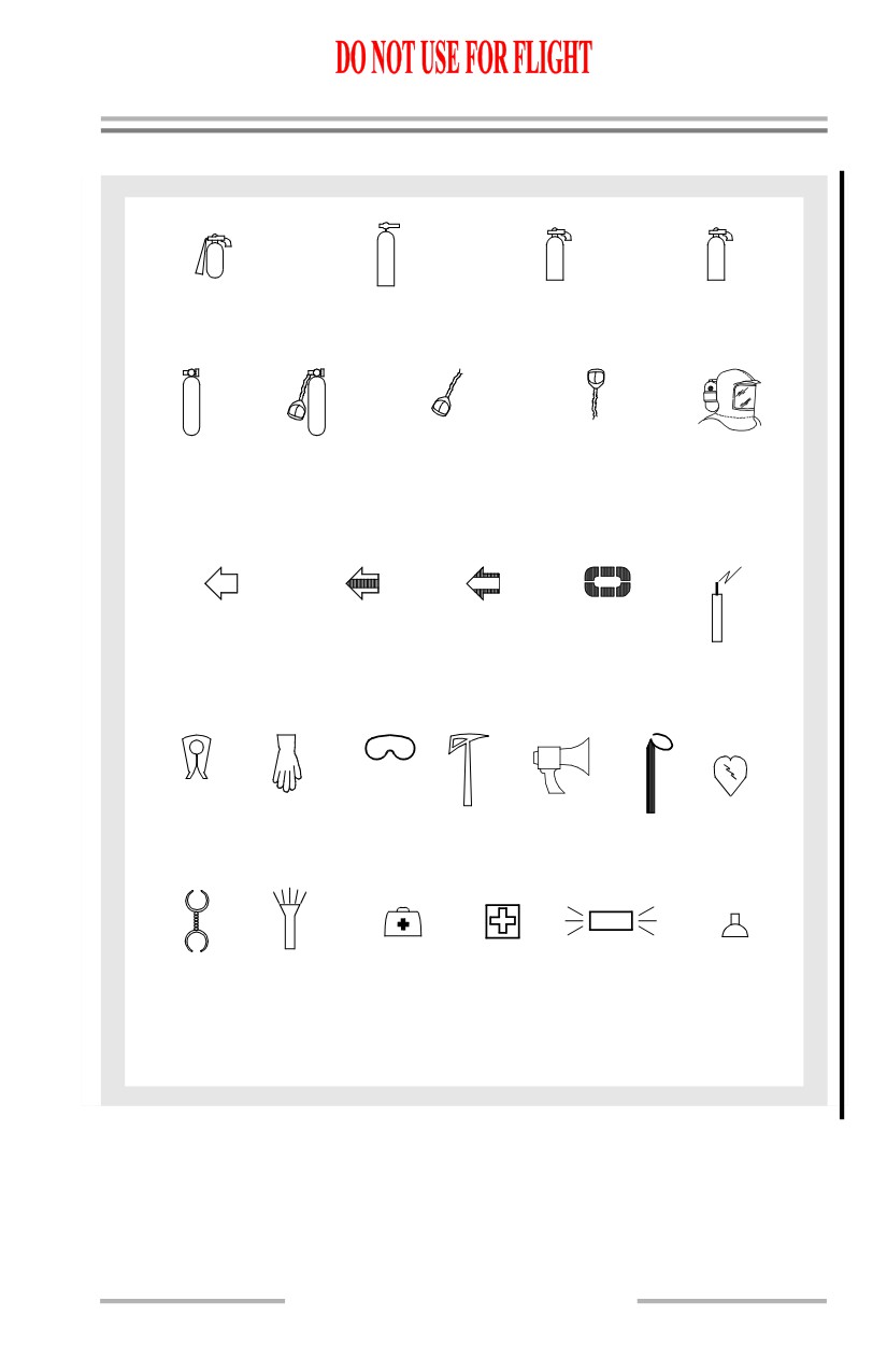
Emergency Equipment Symbols
C
H
B
O
2
D
C
2
C
O
F
CO2
WATER
DRY CHEMICAL
BCF
EXTINGUISHER
EXTINGUISHER
EXTINGUISHER
EXTINGUISHER
O
O
2
2
DISPOSABLE
PORTABLE
PORTABLE
FULL FACE
SMOKE
OXYGEN BOTTLE
OXYGEN BOTTLE
OXYGEN MASK
OXYGEN MASK
HOOD
WITH SMOKE
MASK ATTACHED
EXIT PATH
EXIT PATH
LIFE RAFT
EXIT PATH
WITH ESCAPE
WITH ESCAPE
WITHOUT ESCAPE
STRAP
SLIDE
EMERGENCY
STRAP
TRANSMITTER
LIFE
SMOKE
VEST
PROTECTIVE
GOGGLES
CRASH
MEGAPHONE
BATON
AED
GLOVES
AXE
EXIT
HANDCUFFS
FLASHLIGHT
EMERGENCY
FIRST AID
PORTABLE
RESUSCITATOR
MEDICAL KIT
KIT
EXIT LIGHT
NOTE: Some symbols do not apply to all configurations.
1.40.19
Airplane General, Emergency
Equipment, Doors, Windows -
Systems Description
Boeing 737 Operations Manual
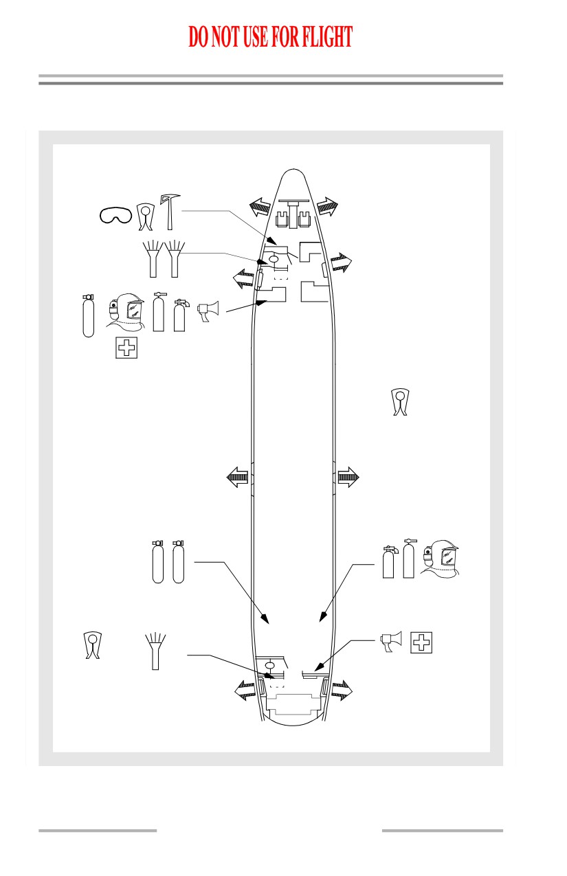
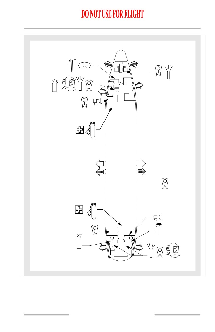
Emergency Equipment Locations
[Option - Typical 737-600/700 with optional emergency equipment]
(3)
(4)
G1
LA
AA
(2)
C
G2
H
O
2
B
2
O
C
F
UNDER EACH
PASSENGER SEAT
(2)
H
O
O
B
2
2
2
C
F
O
AT EACH
ATTENDANT
STATION
LD
(2)
AA
A = ATTENDANT SEAT
l = LAVATORY
G4B
G = GALLEY
1.40.20
Airplane General, Emergency
Equipment, Doors, Windows -
Systems Description
Boeing 737 Operations Manual
[Option - 737-800/900 with optional emergency equipment]
(3)
(3)
(2)
G1
B
LA
C
F
AA
(2)
(2)
(2)
G7
G2
(5)
INFANT
(2)
O
2
A = ATTENDANT SEAT
l = LAVATORY
G = GALLEY
UNDER EACH
PASSENGER SEAT
(2)
O
2
B
C
G
F
H
(5)
LD
LE
2
INFANT
O
AA
AA
G4B
EACH ATTENDANT
1.40.21