PGEV and PGE Locomotive Governors. Manual - part 8
 

  Index      Locomotives - books     PGEV and PGE Locomotive Governors - manual 1990


Search            


Content   ..  6  7  8  9   ..


PGEV and PGE Locomotive Governors. Manual - part 8


Manual 36703 

PGEV and PGE Locomotive Governors 


Woodward 

21 


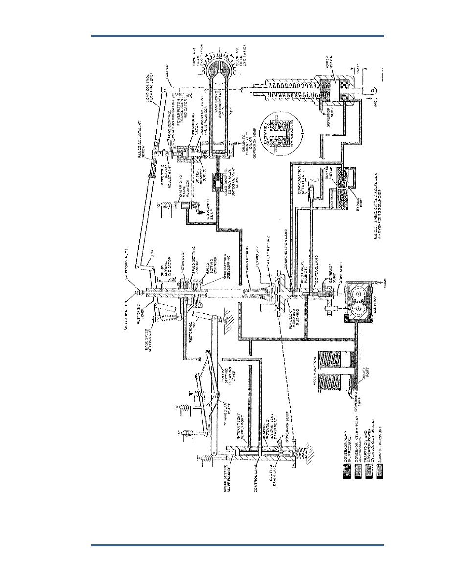
Figure 3-1. Schematic Diagram of Typical PGEV Governor 

PGEV and PGE Locomotive Governors 

Manual 36703 


22 

Woodward 

Speed Setting Decrease 

 
Moving the throttle to a lower step de-energizes (or energizes) one of more of the 
solenoids and causes a reverse action to that of speed setting increase. The 
triangular plate moves upward, being held in contact with the solenoid plungers 
by a loading spring. This allows the loading spring under the pilot valve plunger 
to un-center (raise) the plunger which allows oil to drain from the speed setting 
cylinder. The upward movement of the speed setting piston is transmitted 
through the restoring linkage to re-center the plunger. 


Normal Shutdown 

(See Figure 3-1) 
 
Under normal operating conditions, the engine is shut down by moving the 
throttle to the STOP position. This energizes the D solenoid pushing the rotating 
bushing down and opening the control port to drain the oil from the speed setting 
cylinder. The speed setting piston then moves up lifting the shutdown nuts and 
shutdown rod in the process. This lifts the governor pilot- valve plunger, draining 
oil from the buffer compensation system and allowing the power piston to move 
down to the shutdown (no fuel) position. The upward movement of the speed-
setting piston is limited by the stop screw. 
 
The speed-setting-piston stop screw (Figure 3-1) limits piston rod travel. 
Restarting the engine is easier because less oil volume is required to move the 
speed setting piston down. 


Load Control Section 

(Figure 3-1) 

 
In most governor applications, the primary function of the governor is to 
automatically maintain a specific engine speed under varying load conditions by 
controlling the fuel flow to the engine. With the locomotive governor, a secondary 
function is included to maintain a constant engine power output at each specific 
speed setting. Thus, for each throttle setting, there is both a constant engine 
speed and a predetermined, fixed rate of fuel flow required. To satisfy both 
conditions, the load on the engine must be adjusted as the locomotive operating 
conditions (speed and locomotive auxiliaries); vary and it is the function of the 
load control to do this. 


Maintaining a constant engine speed does not mean that locomotive 
road speed will also be constant. 


Control of engine load is achieved by regulating engine speed and fuel setting. 
This is done by adjusting the generator field-excitation current through the use of 
a vane servo controlled variable resistance in the generator-field circuit. The 
vane servo is controlled by the load control pilot valve and related linkage in the 
governor. The load-control linkage is so arranged that for each speed setting 
there is only one fuel setting (engine power output) at which the load- control 
pilot-valve-plunger will be centered. 
 
An increase or decrease in either governor speed setting or engine load will 
change fuel flow. The power piston moving in either the increase or decrease fuel 
direction will (through the floating lever linkage) move the load-control pilot valve 
up or down respectively. The vane servo decreases or increases field excitation 
and in turn engine load. 


Manual 36703 

PGEV and PGE Locomotive Governors 


Woodward 

23 


Figure 3-2. Sectional Diagram PGE Governor 

PGEV and PGE Locomotive Governors 

Manual 36703 


24 

Woodward 

In some applications, the vane servo is a remote unit connected to the governor 
through tubing and uses oil from the engine lubricating system for its operation. 
The vane servo may be either a rotary or piston type. In other applications, the 
vane servo is integral with the governor and uses governor oil for its operation. 
The integral unit consists of a commutator about which a set of moveable 
brushes rotate to change the value of the resistance in the generator field 
excitation circuit. The brushes are driven by the servomotor which, in turn, is 
controlled by the load-control pilot valve. Remote units, usually provided by the 
locomotive manufacturer, differ in size and construction from the integral unit, 
however, the method of control and operation is essentially identical. 
 
The load-control pilot valve plunger is suspended from the load-control floating 
lever. The lever is connected to the power-piston tailrod at one end and to the 
speed setting piston rod at the other end. Any movement of either or both pistons 
causes a corresponding movement of the plunger which is housed within a non-
rotating bushing. Pressure oil is supplied to the plunger either externally from the 
engine lubricating oil system or internally from the governor oil pump. Two lands 
on the plunger control the flow of oil to or from the vane servo. When internal 
governor oil is used for operation of the vane servo, a supply (cutoff) valve is 
provided in the oil supply passage to the load-control valve. The supply valve is 
closed during starting so that all available oil from the governor oil pump is 
delivered to the speed setting and power pistons to quickly open the fuel injectors 
and thus minimize cranking time. After the engine starts, the increase in governor 
oil pressure opens the supply valve and restores normal load control system 
operation. This valve also serves a secondary system to control the vane servo 
response rate (timing). 


Operation with Load Increase 

 
Assuming that the train is in motion and that the electrical load is balanced with 
the desired engine fuel (power output) at the existing governor-speed setting, the 
load control system will be stationary with the pilot valve plunger centered. When 
a compressor turns on (or any situation occurs that increases load) electrical load 
on the generator is increased and transmitted to the engine. Engine speed 
decreases and the governor increases fuel flow to bring the engine back to the 
preset speed while still carrying the added load. 
 
The power piston moves upward simultaneously raising the right end of the load 
control floating lever which, in turn, lifts the pilot valve plunger above center. This 
directs pressure oil through the upper control port in the bushing to the decrease-
excitation side of the vane servo while opening the lower port in the bushing to 
drain. With a reduction in load, the engine will overspeed and the governor will 
then act to reduce fuel. The reduction in field excitation current and engine fuel 
will continue until the power piston and floating lever have returned to their 
original position. This re-centers the pilot valve plunger and stops the 
servomotor. Consequently, the electrical load is reduced sufficiently to again 
balance the required engine power output (fuel flow). At this point, the engine will 
have also returned to an on-speed condition. 


Content   ..  6  7  8  9   ..