PGEV and PGE Locomotive Governors. Manual - part 5
 

  Index      Locomotives - books     PGEV and PGE Locomotive Governors - manual 1990


Search            


Content   ..  3  4  5  6   ..


PGEV and PGE Locomotive Governors. Manual - part 5


Manual 36703 

PGEV and PGE Locomotive Governors 


Woodward 


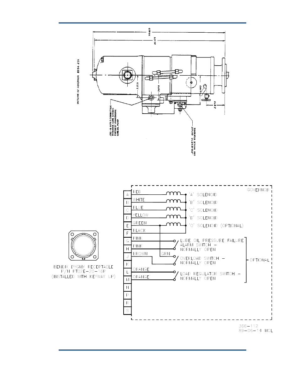
Figure 1-7b. Outline Drawing of PGEV Governor with Integral Vane Servo, Water 

Box, and Linear Output 

(Do not Use for Construction) 


Figure 1-8. Typical Wiring Diagram 


PGEV and PGE Locomotive Governors 

Manual 36703 


10 

Woodward 


Figure 1-9. Typical Wiring Diagram for 12 Pole Connector 


Figure 1-10. Typical Wiring Diagram for 16 Pole Connector 

Manual 36703 

PGEV and PGE Locomotive Governors 


Woodward 

11 

Chapter 2. 

Installation and Adjustment 


Introduction 

 
Refer to Figure 1-5, 1-6, or 1-7 for complete physical dimensions of the governor. 
Use care in handling the governor; be careful to avoid striking the drive shaft. Do 
not drop or rest the governor on its drive shaft. Such treatment could damage the 
governor. 


Installation 

 
Take care to ensure that the governor is mounted squarely and that the drive 
connection to the engine drive is properly aligned. Do not use force when making 
this connection. A gasket must be used between the governor base and 
mounting pad. Misalignment of the governor with respect to its mounting pad, or 
engine drive connection, or too tight a fit between governor drive and drive 
coupling can result in excessive wear or seizure and may also cause undesirable 
"jiggle" at the output shaft. 
 
The linkage from the governor to the engine fuel system must be properly aligned 
to eliminate binding and/or excessive backlash. The relationship of "piston gap" 
(see Figure 3-1) or terminal shaft angular position to rack position must be 
adjusted in accordance with the engine manufacturer's specifications. 


Due to the location of the compensation cutoff port in the power 
cylinder wall, the governor/fuel rack linkage must be adjusted so the 
power piston "gap" does not exceed 1-1/32 inches (26.2 mm) at no 
load idle. 

 
Make the hydraulic and electrical connections required for the particular model 
governor being installed. Fill governor with oil to a level between lines on oil 
gauge sight glass. Fill the governor with oil to the line on the oil gauge ( on 
models with only one line on the gauge). Oil must be clean and of a grade 
suitable for the particular operating conditions (see Specifications). Recheck oil 
level after engine is started and add oil as necessary. Do not overfill. 


Maintain the correct oil level at all times. 


On governors equipped with an integral vane servo and resistor 
pack, the cavity around the resistor pack (rheostat) must be 
completely filled with oil before putting a load on the unit. Without oil 
for cooling, sufficient heat can be generated to overheat the resistor 
wiring and insulation. This caution does not apply to governors with 
integral vane servos and ceramic resistors. 

PGEV and PGE Locomotive Governors 

Manual 36703 


12 

Woodward 

To fill the cavity when the governor is on a test stand, energize or de-energize 
the overriding solenoid. This lowers or raises the overriding valve plunger, raising 
or lowering the load control pilot valve plunger and releasing oil to the rheostat 
cavity. When filling the rheostat cavities on the engine, move the throttle from the 
IDLE position to number two position. The load control pilot valve plunger 
changes position, allowing oil to enter the rheostat cavity. Changing load with the 
throttle should be done a few times to be sure the cavity is full. The cavity is full 
when the oil completely fills the area behind the indicator glass. 
 
Check governor oil level and add oil if necessary. 


The engine, turbine, or other type of prime mover should be 
equipped with an overspeed shutdown device to protect against 
runaway or damage to the prime mover with possible personal injury, 
loss of life, or property damage. 
 
The overspeed shutdown device must be totally independent of the 
prime mover control system. An overtemperature or overpressure 
shutdown device may also be needed for safety, as appropriate. 


Adjustments 

 
Normally, the only requirements for putting a new or overhauled governor into 
service are bleeding entrapped air and adjusting the compensation needle valve 
to obtain maximum stability. All other operating adjustments are made during 
testing at the factory in accordance with the engine manufacturer's specifications 
and should not ordinarily require further adjustment. If found necessary to 
change or readjust speed settings or other operating adjustments, refer to the 
engine manufacturer's instructions. Do not attempt internal adjustment of the 
governor unless thoroughly familiar with the proper procedures. 


Compensation Needle Valve Adjustment 

 
The compensation needle valve is an adjustable part of the compensation 
system. Its setting, which directly affects governor stability, depends upon the 
individual characteristics of the prime mover: 
 
1.  With the prime mover operating at IDLE, open the compensation needle 

valve several turns to cause the engine to hunt. In some cases, opening of 
the needle valve alone may not cause the engine to hunt, but manually 
disturbing the governor speed setting will induce the governor to move 
through its full output stroke. Allow several minutes of hunting to remove 
trapped air in the hydraulic circuits. 

 
2.  Close the compensation needle valve gradually until hunting is just 

eliminated. Keep the needle valve open as far as possible to prevent 
sluggishness in the governor response. The needle valve setting varies from 
1/16 to 2 turns open. Never close it tight, the governor cannot operate 
satisfactorily when this condition exists. 

 
3.  Check the governor stability by manually disturbing the governor speed setting. 

The compensation adjustment is satisfactory when the governor returns to 
speed with only a slight over - or undershoot. Once the needle valve 
adjustment is correct, it is not necessary to change the setting except for large, 
permanent changes in temperature which affect governor oil viscosity. 


Content   ..  3  4  5  6   ..