Lotus Eleven/Elise/Exige. Manual - part 125


  Index      Lotus     Lotus Eleven/Elise/Exige (engine 1ZZ/2ZZ/1ZR) - service repair manual 2004 year


Search            


Content   ..  123  124  125  126   ..


Lotus Eleven/Elise/Exige. Manual - part 125


Lotus Service Notes   


       Exige S/C

Page 6

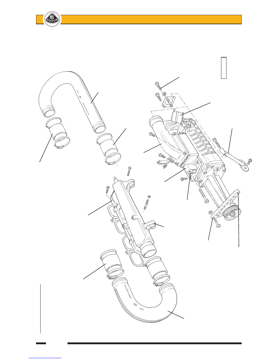
Supercharger & Ducting


Connection to chargecooler inlet

Connection to chargecooler outlet  


New inlet manifold


Chargecooler 


inlet duct 


Supercharger outlet connector


Supercharger outlet elbow 


Supercharger 


outlet adaptor


Mounting lug for


supercharger 


Fixing point 


Swan neck


Chargecooler 


to manifold 


adaptor fixings 


outlet duct 


(supercharger


inlet)


Fixed to engine 


mounting plinth 


By-pass valve


capsule


pl4207ls/pl4209lr


Strut to clutch 


Alternator anchor 


slave cylinder mounting

Page 7


Lotus Service Notes   


       Exige S/C


                                     Flexible bellows

      Adaptor to chargecooler

                                                Air duct

Chargecooler                                        from roof

radiator                                            scoop        FRONT


                                          Rubber mounting

                                            Bracket to inlet manifold

                                            and cam cover

Bracket to 

inlet manifold                                                 

                                      Fixing to inlet manifold

  Rubber mounting

Chargecooler outlet duct        Inlet manifold        Chargecooler

                                                        Chargecooler 

                                                        inlet duct

Boss 

for 5th

injector                                                        Standard

(240R)                                                        airbox

Supercharger

outlet elbow

      Supercharger

      outlet adaptor

                                      Electronic 

                Supercharger              throttle body


        FRONT                Throttle body 

                          adaptor                                      

le2047a

   pl4610mx


Lotus Service Notes   


       Exige S/C

Page 8

Air is drawn from the standard air cleaner through the throttle body and adaptor and into the supercharger 

axial intake port.  From the outlet port on the compressor top surface, the air is directed through a 'U' bend duct 

to the LH end of an air/air chargecooler rubber mounted above the engine, where airflow gathered from the roof 

duct is used to cool the compressed intake charge.  The chargecooler uses four rubber bobbins attached to two 

mounting brackets themselves secured to the inlet manifold and cam cover.  A charge air temperature sensor 

is mounted in the outlet tank of the chargecooler.  The cooled air exiting from the RH end of the chargecooler 

flows via another 'U' bend duct into a cast alloy intake plenum/manifold.  The whole intake tract has been kept 

as short as possible, and uses large diameter ducting and generously radiused bends to optimise airflow and 

efficiency to the particular benefit of throttle response and fuel economy. 

A re-shaped breather pipe is used to connect the crankcase breather spigot to the cam cover and circum-

navigate the supercharger.

On the 240R and Cup cars, a stainless steel 'level one' sports exhaust muffler (LOTAC05334) is fitted to 

provide an acoustic enhancement and features enlarged, slash cut tailpipes and a near 20% weight saving 

over the standard system.  Exige S models use a stainless muffler with a single, oval shaped, tailpipe design.

240R models use 4 standard port fuel injectors together with an additional 5th injector mounted in the 

intake end of the inlet manifold.  Other 240 and upwards versions, and all USA cars, use 4 special high-flow 

port injectors.  The Lotus engine management system is reprogrammed to suit each engine specification and 

incorporates additional functions to control the fifth injector (240R) and supercharger by-pass valve.  The boost 

characteristics have allowed the switching point from low to high lift cam profile to be modulated between 4,500 

and 6,200 rpm (at normal running temperature).  The airbox flap valve opens at 4,500 rpm.  240R models use 

a mechanical cable operated throttle body, whereas the Cup and Exige S cars use '06 model electronic throttle.  

Twin front mounted oil/air coolers are fitted to all supercharged Exige.

Accusump - 240R & Cup 240

To provide protection against the possibility of oil starvation caused by the extreme g-forces possible with 

track use on slick tyres, the 240R and Cup cars are fitted with an Accusump oil storage system.

A 2-litre Accusump reservoir is mounted in the rear luggage compartment, plumbed into the LH oil cooler 

return hose at the front of the engine bay, with the connecting hose routed over the RH rear wheelarch.  The 

device comprises an alloy cylinder divided by a sliding piston, one side of which is connected to the engine 

oil supply, with the other containing pressurised air.  With the engine running, the cylinder is charged with oil 

provided by the engine oil pump, but if the pressure should drop for a short period due to oil pump pick up pipe 

exposure during extreme braking or cornering events, the accumulator air pressure forces the stored oil into 

the engine lubrication system to maintain continuity of oil supply until normal conditions are resumed. 

A one-way valve at the oil cooler connection of the 'T'- piece ensures that the oil discharged from the Ac-

cusump is directed into the oil pump and not the cooler.  An Electric Pressure Control (EPC) non-return valve is 

fitted at the connection to the Accusump cylinder, to allow cylinder charging when oil pressure is above 35 - 40 

psi, and cylinder discharging at engine oil pressures below 35 - 40 psi.   The EPC is also linked to the ignition 

switch such that with the ignition switched on the valve is open to allow oil flow, and with ignition off the valve 

is closed to retain oil within the reservoir.

Normal Operation

When the ignition is turned on, the EPC valve is opened, allowing the pressurised oil stored in the reser-

voir to flow out into the engine and prime the oil galleries and bearings ready for start up.  When the reservoir 

has been emptied, the pressure gauge on the end of the reservoir will indicate the pre-charge pressure which 

should be 7 - 15 psi.

When the engine is started, engine oil pressure will force the reservoir piston back, such that the reservoir 

air pressure gauge will indicate engine oil pressure.  At pressures above 40 psi, the electric valve is switched 

off, enabling the non-return function to allow oil flow only from the engine to the Accusump.  The pressure of 

stored oil will accord with the highest engine oil pressure achieved until either; a) pressure falls below 40 psi, 

at which point the valve opens, or b) the ignition is switched off, and then on again, opening the valve as de-

scribed above.

With cold oil, 80 psi may be generated, but idling at normal running temperature should produce around 

30 - 40 psi.  Note that the pressure reading on the reservoir gauge is damped and will lag behind the actual 

instantaneous pressure.  A pressure relief valve in the end of the reservoir protects the equipment from over-

pressure damage.  If oil is seen to escape from this valve, a fault in the lubrication system is indicated, or 

excessive rpm have been used with cold oil.

When the ignition is switched off, the electric valve closes and the oil stored in the Accusump at that time 

is retained in the cylinder ready for re-starting.

Page 9


Lotus Service Notes   


       Exige S/C

Routine Checks

Be aware that the indicated oil level on the dipstick will depend on the amount of oil stored in the Accu-

sump, which itself is dependent on the both the Accusump pre-charge air pressure and the engine oil pressure 

when the ignition was switched off.

Before checking the oil level, the Accusump pre-charge pressure should first be checked; turn on the 

ignition to open the EPC valve and allow the stored oil to be discharged from the Accusump.  The pressure 

gauge reading will drop during this discharge, but should then register 7 - 15 psi representing the pre-charge.  

If necessary, adjust the air pressure using tyre inflator equipment on the Schraeder valve adjacent to the gauge 

and set to 15 psi.

The oil level should now be above the top mark on the engine dipstick.  To check for correct oil level, the 

engine should be started at idle to charge the Accusump until the pressure gauge registers 40 psi.  If idle oil 

pressure is below 40 psi, increase rpm until 40 psi is achieved and then switch off.  This pressure should then 

be retained in the cylinder.  If idle oil pressure is over 40 psi, the engine must be run to normal running tem-

perature before switching off and then re-starting as above.

 After a suitable oil drainback pause, the sump oil level may then be inspected on the disptick, and the 

level corrected to the top mark.  It is important to maintain oil at this level to accommodate the oil transfer into 

the Accusump at pressures greater than 40 psi.  Be aware that checking the oil level under any conditions other 

than 15 psi pre-charge and 40 psi oil pressure will produce inconsistent results.

Oil Changing

Before draining the sump, the ignition should first be switched on to open the EPC valve and allow the 

Accusump to discharge the stored oil into the sump.  Check that a pressure of 7 - 15 psi remains in the Ac-

cusump at the end of this process, and if necessary top up the pressure using tyre inflating equipment on the 

Schraeder valve next to the gauge and set to 15 psi.

The oil can then be drained in the usual way, with the quantity contained in the oil cooler lines disregarded 

for the purposes of routine maintenance.  If an engine failure has occurred, with possible debris contamination 

of oil hoses and coolers, it is recommended to replace both oil coolers, and to replace or thoroughly flush the 

feed and return hoses.  At each service interval the in-line filter gauze in the hose between the Accusump and 

'T'- piece, should be renewed. 

After renewing and pre-filling the engine oil filter, and replacing the in-line filter gauze (see above), refill the 

sump to about 10mm above the top mark on the dipstick.  Start the engine and allow to idle.  Do NOT rev the 

engine or drive the car.  The Accusump will take up to 2 litres of oil from the sump to store within the cylinder.  

        Accusump reservoir                             Air pressure gauge

    EPC valve

    assembly                                                    FRONT

                                                    Mounting clamp to 

                                                    boot floor

In-line 

filter                                To LH port                    From oil 

                                  on sandwich                  cooler

                                  plate


                pl4015cLR


Content   ..  123  124  125  126   ..