Lotus Eleven/Elise/Exige. Manual - part 64


  Index      Lotus     Lotus Eleven/Elise/Exige (engine 1ZZ/2ZZ/1ZR) - service repair manual 2004 year


Search            


Content   ..  62  63  64  65   ..


Lotus Eleven/Elise/Exige. Manual - part 64


   Lotus Service Notes

                Section JJ

Page 9

JJ.6 - PARKING BRAKE MECHANISM

Operation of the parking brake lever applies a pull to a short link cable which connects via a horseshoe

compensator to the centre of a single cable linking the two rear callipers.  At each calliper, the cable connects
to a lever which operates the hydraulic piston by mechanical means:

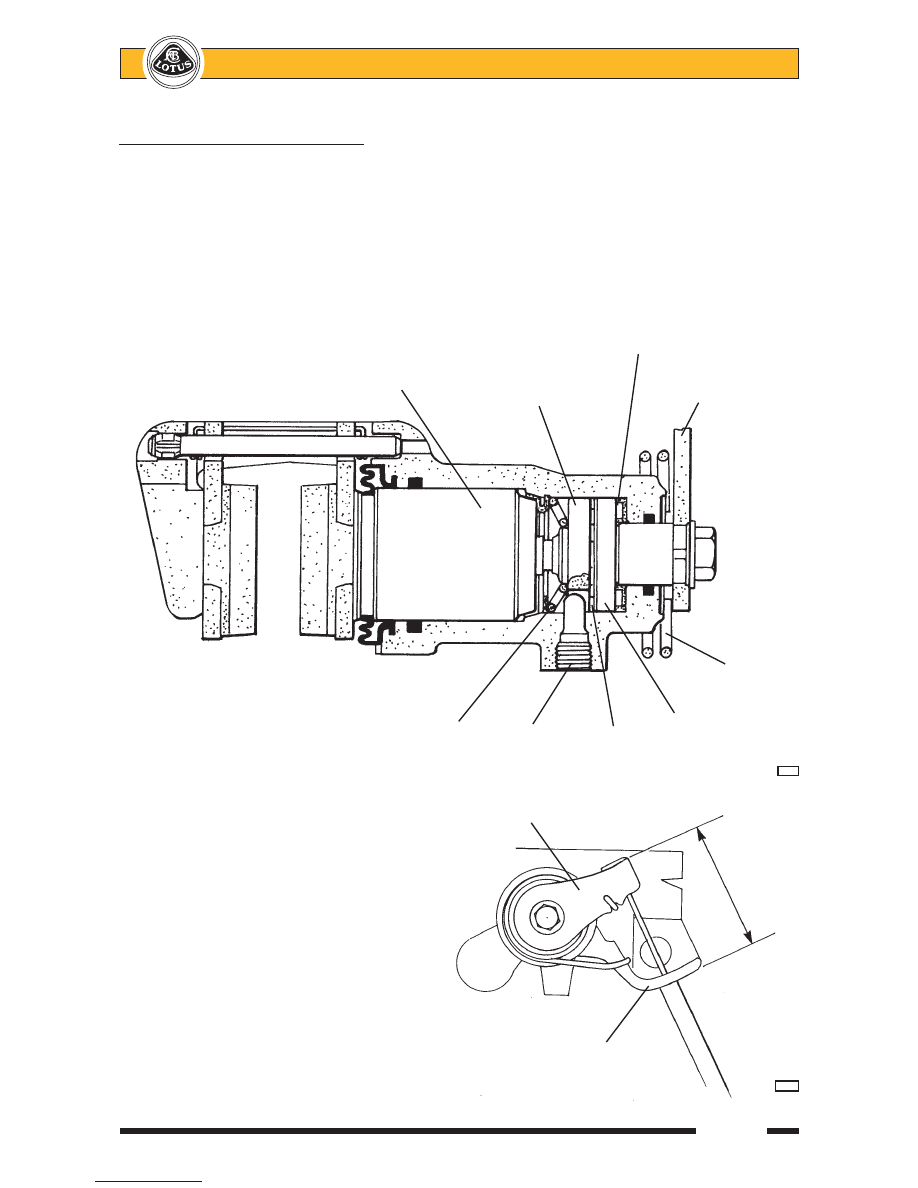
Movement of the calliper lever causes rotation of one of a pair of steel discs, rotation of the other being

restrained by a stop bolt in the cylinder.  Hardened balls housed in ramps machined in the discs, force the discs
apart, and in so doing, apply an axial force to the piston via a screwthread and nut.  The nut is restrained in the
piston by a one way clutch which grips the nut when the parking brake is applied, but  allows it to turn when the
mechanism relaxes, or when the piston is operated hydraulically by the footbrake.  In this way, the mechanical
mechanism is adjusted automatically to compensate for pad wear.

For the auto adjustment system to

function correctly, it is essential that each
calliper parking brake lever is allowed to return
fully when the brake is released, and is not
prevented from doing so by maladjustment of
the parking brake cable.  To check that the
calliper levers are fully returned; with the
parking brake ‘off’, measure the distance
between the cable abutment and calliper lever
as shown.

Needle roller
thrust bearing

Piston
assembly

Driven

Operating

disc

lever

Lever
return
spring

Driving

Return

Stop

Balls

disc

spring

bolt

in ramps

        j126

Calliper park brake lever

  76 mm

Cable abutment

          139


   Lotus Service Notes                                  Section JJ

Page 10

After verifying this dimension, any slack in the rear cable may be adjusted out at the left hand outer cable

abutment, which is integral with the pivot bracket for the front leg of the lower wishbone.  Remove the engine
bay undertray for access.  After adjustment, re-check the calliper lever ‘off’ dimension.

The parking brake lever is mounted in a steel bracket which also houses the gearchange lever, and is

bolted to the seat mounting crossmember at the front, and to the floor rear crossmember.  The parking brake
lever is secured by two bolts fixing the ratchet quadrant to the bracket.  Access to the lever is available after
removing the cockpit centre trim panel:

LH lower wishbone
front pivot bracket

Horseshoe compensator

Parking brake cable adjuster

         j169

Parking brake lever

Ratchet quadrant

Primary cable

Parking brake tell tale switch

Mounting bracket

Fixing point to
seat rear
crossmember

         j189

   Lotus Service Notes

                Section JJ

Page 11

-

Unscrew the gear lever knob.

-

Release the fixing screw at either side of the gear lever shroud base.

-

Remove the single screw retaining the rear bulkhead centre pocket, and then the two screws securing the
rear shroud.  Disconnect the auxiliary power socket.

-

Lift the centre trim panel, label and disconnect the CDL switch and (if fitted) hazard switch, and release
the gear lever gaiter.

Note that the parking brake/gearchange lever mounting bracket is not drive handed, but is offset, via

alternative fixing holes in the chassis, towards the passenger side.  The ratchet pawl operates a micro switch
to light the 'brakes' tell tale lamp in the instrument panel whenever the ignition is switched on and the parking
brake is applied.  The short front cable is connected to the lever assembly by a clevis pin with spring retaining
clip.  When carrying out any work in this area, take care not to damage or misroute the electrical main harness.

JJ.7 - BRAKE DISCS

All four wheel brakes use a brake disc which is sandwiched between the wheel and its hub flange, being

centralised by the hub spigot, and transmitting torque via the clamping force of the road wheel bolts.  A
countersunk screw is used to retain the discs for convenience when servicing.

The same disc is used at each corner of the car, and features cast iron construction with internal curved

vane cooling and cross-drilling.  The opposite direction of rotation of the curved vanes on each side of the car
does not significantly affect the cooling performance of the disc.  The condition of the brake disc friction
surface is a major factor in brake performance and feel, with a good surface quality and minimal run-out and
thickness variation being required.  After an extended lay up, some surface corrosion may develop on the discs
which will cause a degradation in braking quality until the surfaces are cleaned up by normal brake action.
Excessive run-out or thickness variation as a result of overheating or extended wear, may cause brake judder
and/or extended pedal travel due to pad 'knock off'.  Scoring and ridging of the braking surfaces will be exac-
erbated by operation in dusty or unmetalled road environments, and will reduce braking performance.

No skimming or re-surfacing of the brake discs is recommended.  If the disc becomes badly scored, or is

out of specification in any way, it should be renewed.  NOTE: Ensure that there is no discernible free play in the
wheel bearings before attempting to measure  brake disc run-out.  If disc run-out exceeds the service maximum,
check the hub run-out before replacing the disc.
Brake disc thickness:

New

26.0 mm (1.02 in)

Service  minimum

24.0 mm (0.98 in)

Runout:

New maximum

0.03 mm (0.001 in)

Service maximum

0.10 mm (0.004 in)

Hub:

Disc mounting face run-out max.

0.04 mm (0.0015 in)

Front Disc Replacement
1.

Remove the road wheel.

2.

Remove the two bolts securing the brake calliper to the hub carrier, and withdraw the calliper from the
disc. Secure clear without straining the flexible hose.

3.

Remove the single countersunk screw, and withdraw the disc from the hub.

4.

Before re-fitting a disc, ensure that the mating face between disc and hub is scrupulously clean.  Mount
the disc onto the hub and align the wheel bolt holes.

5.

Apply Permabond A130 (Blue - A912E7033) to the threads of the calliper fixing bolts.  Fit the calliper over
the disc and secure to the hub carrier with the two bolts.  Tighten to 45 Nm (33 lbf.ft).

6.

Refit the road wheel and operate the brakes before driving the car to set the brake pad position.

Rear Disc Replacement

Replacement of the rear discs is similar to that for the front discs, except that if the brake pads are

removed, it is not necessary to remove the brake calliper to enable the disc to be withdrawn from the hub.


   Lotus Service Notes                                  Section JJ

Page 12

JJ.8 - BRAKE CALLIPERS

The front brake callipers are manufactured by A.P. Racing, and are to be dismantled or overhauled only

by their factory at Wheeler Road, Seven Stars Industrial Estate, Coventry, CV3 4LB.
Torque settings:

Flexible hose to front caliper:

22 Nm

Front caliper to hub carrier: 45 Nm

The Brembo rear brake callipers may have the sliding pins overhauled as detailed below, but any signs of

hydraulic leakage from the cylinder indicate that the unit should be replaced.

Rear Calliper Sliding Pins

The sliding bushes and sleeves of the Brembo rear callipers may be replaced without disturbing the

hydraulic connection:

a)

Disconnect the parking brake cable from the calliper.

b)

Remove the cap head bolt securing the bottom guide bush to the hub carrier.

c)

Remove the hex. head bolt securing the top guide bush to the hub carrier, and withdraw the calliper from
the car with the brake hose still connected.

d)

Slide out the lower steel guide sleeve and withdraw the bush/boot from the calliper.  Pull the boots off the
top steel guide bush and slide out the bush from the calliper.

e)

Clean the guide bores in the calliper body with brake cleaner.  Lubricate the new bushes and boots with
silicone grease provided in the repair kit, and reassemble into the calliper in reverse order to disassembly.

f)

Refit the calliper to the hub carrier using Permabond A134 on the threads of both bolts, torque tightening
the two fixings to:
Upper M10 bolt;

45 - 50 Nm (33 - 37 lbf.ft)

Lower M8 caphead; 26 - 30 Nm (19 - 22 lbf.ft)

g)

Reconnect the parking brake cable and operate the footbrake to reposition the pads before driving the
car.

Top guide bush boots

Top guide bush

Lower guide
boot

         j163

Split plastic bush

Lower guide sleeve


Content   ..  62  63  64  65   ..