Lotus Eleven/Elise/Exige. Manual - part 29


  Index      Lotus     Lotus Eleven/Elise/Exige (engine 1ZZ/2ZZ/1ZR) - service repair manual 2004 year


Search            


Content   ..  27  28  29  30   ..


Lotus Eleven/Elise/Exige. Manual - part 29


Page 10


Lotus Service Notes   


    Section DH

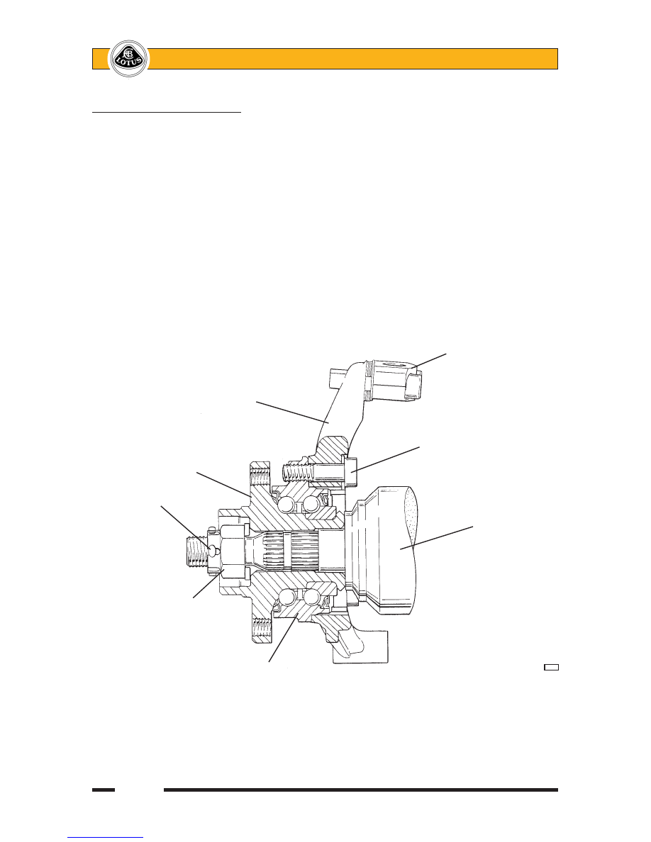
                                                    Top ball joint plinth

                Hub carrier

                                               Hub to carrier fixing bolt

            Hub

    Split pin

                                                        Driveshaft

    Castellated nut

          Double row ball bearing                 


 d39

To Replace Hub Bearing Assembly

1.  With the wheel removed, apply the parking brake, remove the split pin from the nut retaining the driveshaft 

in the hub, and release the nut.  

2.  Release the two fixing bolts, and remove the brake caliper from the hub carrier.  Support clear of the brake 

disc without straining the flexible hose.  Release the single countersunk screw and withdraw the brake 

disc from the hub.

3.  Disconnect the wheel speed sensor harness from the hub unit.

4.  Using a Torx socket, release the three bolts securing the hub bearing unit to the hub carrier, and withdraw 

the unit from the hub carrier and driveshaft.  If necessary, use a suitable puller tool to press the shaft from 

the hub, but on no account allow an extension force to be applied to the driveshaft. 

5.  Fit the new hub bearing unit in reverse order to disassembly, with the following notes:


- Torque tighten the three Torx bolts securing the hub bearing assembly to the hub carrier to 90 Nm.


- Torque tighten the driveshaft nut to 220 Nm and retain using a new split pin.


- Pump the brake pedal to reposition the pads before driving the car.

Page 11


Lotus Service Notes   


    Section DH

DH.5 - TRACK USE CHASSIS REAR BRACE KIT - LOTAC05377

The purpose of the kit is to provide a 'double shear' mounting for the inboard ends of the rear toe-links and 

spread the load distribution into the chassis over a wider base.  New spherical joints are used on the inboard 

ends of the toe-links, with a tubular steel crossbrace interconnecting the two pivot bolts and anchoring to the 

rear engine steady mounting on the subframe.  For cars used on closed circuits, this arrangement provides an 

increased tolerance to abuse.  It may be retrofitted on any Elise 111R/'04 Exige/USA Elise (i.e. Toyota power-

train cars).

The rear toe-links comprise the existing outboard taper shank ball joint and toe-link tube, but the inboard 

joint is replaced by a new spherical joint with no integral stud.  A bespoke spacer locates in the orientation 

groove in the (unchanged) subframe and provides a flat surface against which to clamp the pivot ball of the new 

joint.  A flange head bolt passes through the ball joint and inboard pivot bush of the lower wishbone in a similar 

manner to previously, but also locates a brace against the rear 'overhung' end of the ball joint.  The tubular 

crossbrace on factory built cars prior to December '05, links the two inboard joints via machined adaptor lugs 

and turnbuckle adjusters, and is braced directly to the subframe by a welded bracket secured by the engine 

rear steady mounting fixings.  On later factory built cars using a brace kit, the crossbrace is a simple tubular 

link (B120D0040H) without adjusters or subframe bracket.  On these cars, a flat washer A120W4199F is used 

beneath the head of the crossbrace bolts.

Kit Contents                      Part Number    Qty

Tubular Crossbrace, adjustable           A120D0040H    1 

Turnbuckle, crossbrace adjustment         A120D0039F    2 

Locknut, turnbuckle, M12, RH thread        A111W3150F    2 

Locknut, turnbuckle, M12, LH thread        A111W3149F    2 

Flange Nut, brace to subframe, M10        A111W3151F    2 

Adaptor Lug                       A120D0037F    2 

Spherical Joint, toe-link inboard           A120D0036F    2

Spacer, spherical joint to subframe         A120D0035F    2

Pivot Bolt, toe link inboad, M10x120x1.25p    A120W2212F    2

Locknut, pivot bolt, M10x1.25p            A117W3189F    2 

Fitting Instruction                    LSL489        1

Procedure (adjustable type crossbrace)

1.  Remove the rear undertray and diffuser.

2.  At both sides, remove the toe-link inboard/lower wishbone rear pivot fixing nut, release the adjacent heat-

shield fixings and withdraw the ball joint.

3.  Cut a vertical slot in the ball joint heatshield at each side, to accommodate the crossbrace adaptor lug, 

removing only as much material as necessary.

4.  Remove the two rearmost setscrews securing the engine mounting steady bracket to the subframe.  If 

these screws use weldnuts on the subframe, the nuts must be chiselled or ground off.

5.  Fit the locknuts onto the turnbuckles, and screw the LH thread of a turnbuckle into each end of the crossbrace 

tube.  Fit an adaptor lug onto the RH thread of each turnbuckle.  Loosely assemble the crossbrace to the 

underside of the subframe plinth using the original setscrews and new flange nuts.

6.  On each toe-link, measure the distance from the locknut to the centreline of the inboard pivot ball.  Remove 

the old joint from the link, and replace with a new spherical joint set to the same approximate position.

7.  Fit a new spacer into the orientation slot in the subframe before positioning the toe-link ball joint and sliding 

the new pivot bolt through the crossbrace adaptor lug (adjusting the turnbuckle as necessary), ball joint, 

spacer, subframe and wishone and retain with a new M10x1.25p locknut.  Repeat for the opposite side.  

Tighten the pivot bolts 

only at mid-laden ride height of 130mm to 50 Nm.  Re-secure heatshield.

Page 12


Lotus Service Notes   


    Section DH

8.  Tighten the turnbuckle locknuts to 45 Nm whilst holding the adjacent adaptor lug, and then tighten the 

engine steady mountings to 45 Nm.

9.  Adjust rear wheel alignment 

only at mid-laden ride height of 130mm to 1.5mm toe-in each side (± 

0.3mm) and tighten the toe-link ball joint locknuts to 45 Nm.  Ensure ball joints are phased at 90° to each 

other to allow maximum joint articulation.

10.  Refit undertray and diffuser.

Section A thro' lower 

link inboard fixing


                                            Heatshield

  Lower wishbone 

  rear bush                                          Adaptor lug

                                                    Pivot bolt

                                                    New spherical joint

  Self-locking nut


                                      Special spacer washer                 

d46a

                          Welded insert

Toe-link                  Adaptor lug     Turnbuckle      Adjustable type cross-brace tube

                                New spherical                  Brace to

                                joint                        chassis


d48

FRONT

FRONT

Viewed from below

Page 13


Lotus Service Notes   


    Section DH

Section B thro' steady mounting attachment

(adjustable type crossbrace)                                Engine steady mounting

                                                  Cross-brace 

                                                  welded bracket

      Chassis

                                                  Cross-brace tube


d47

FRONT

General view

                       Cross-brace fixing          Adaptor lug

                        to subframe

                                          Turnbuckle

                              Cross-brace                             

d45


Content   ..  27  28  29  30   ..