Lotus Eleven/Elise/Exige. Manual - part 10


  Index      Lotus     Lotus Eleven/Elise/Exige (engine 1ZZ/2ZZ/1ZR) - service repair manual 2004 year


Search            


Content   ..  8  9  10  11   ..


Lotus Eleven/Elise/Exige. Manual - part 10


Page 5


Lotus Service Notes   


    Section AH

AH.3 - REAR SUBFRAME

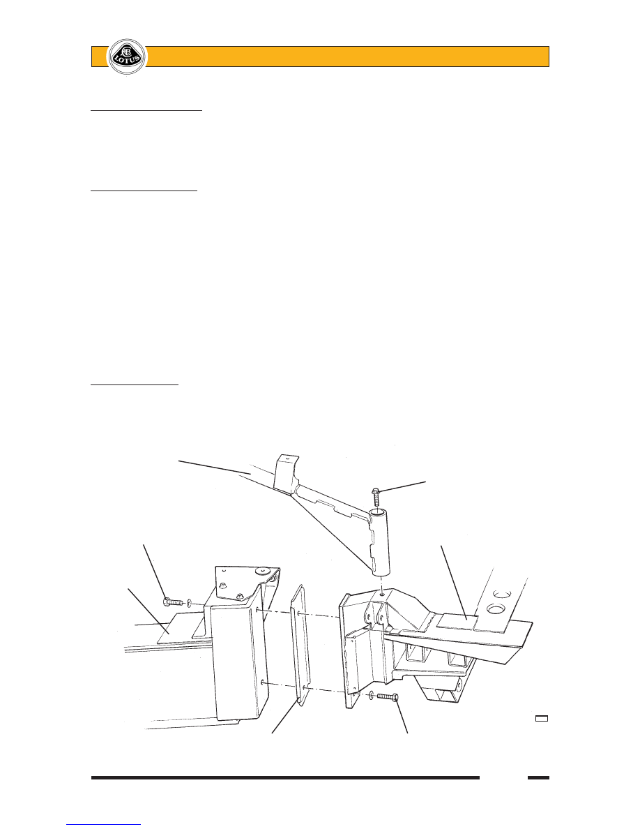
The rear ends of the chassis siderails are linked by a fabricated sheet steel subframe which provides 

mountings for the rear body section, rear suspension pivots, engine rear stabiliser, exhaust muffler and seat 

belt mounting frame struts.  The subframe is secured to the siderails by two M12 bolts at each side, with an 

anti-corrosion shim plate interposed.

To remove rear subframe

1.  Remove the rear clamshell (see section BR).

2.  Remove exhaust heatshields, catalytic converter and muffler.

3.  Disconnect the parking brake cables, wheel speed sensor harnesses and rear brake hydraulics.  Release 

the driveshafts from the hubs, and remove both rear suspension assemblies complete, providing alterna-

tive support for the driveshafts.

4.  Disconnect the inertia switch, and release from the subframe the oxygen sensor harness, wheel speed 

sensor harnesses and brake pipes.

5.  Release the engine rear stabiliser mounting from either the subframe or transmission.

6.  Release the roof hoop backstays from the subframe.  Remove the two bolts each side securing the subframe 

to the chassis flange and withdraw the subframe from the car.

Fitting rear subframe


When bolting the subframe at each side to the chassis rail rear flange, ensure that the anti-corrosion 

shim plate is interposed.  The lower fixing bolts should be inserted from the rear, using a washer and Nyloc nut 

inside the chassis extrusion.  Apply Permabond A130 (A912E7033V) to the threads of the upper bolts before 

fitting from the front into the weldnuts in the subframe.  Tighten all four bolts to 86 Nm.  Continue re-assembly 

in reverse order to disassembly.

Seat belt mounting

frame backstay

                                                  Backstay to subrame

                                                 fixing bolt

Subframe upper 

mounting bolt                                          Rear subframe

Chassis


 a30

                  Anti-corrosion shimplate        Subframe lower mounting bolt

Page 1


Lotus Service Notes   


    Section BQ


BODYCARE & REPAIR

SECTION BQ

                                                     Sub-Section   Page

    General Description                                    BQ.1      3

    Lotus Composite Body Features                            BQ.2      3

    Bodycare                                           BQ.3      4

    Accident Damage Assessment                              BQ.4      5

    Body Panel Bonding Materials                              BQ.5      6

    Replacement of Bonded-On Panels - General                    BQ.6      9

    Front Crash Structure                                   BQ.7      10

    Windscreen Frame                                     BQ.8      12

    Sill Panels                                          BQ.9      16

    Rear Bulkhead                                        BQ.10    17


Page 2


Lotus Service Notes   


    Section BQ

Body Panels

                                Door

                                shell

                Windscreen                           Sill panel

Front access        frame

panel                                     Rear 

                                        window

                                        shroud

                                                            Engine

                                                            cover lid

Front

clamshell

                                      Cabin rear

Door hinge                               bulkhead

cover panel

                                                      Rear clamshell

Front crash

structure

                Chassis frame


      b277b

Page 3


Lotus Service Notes   


    Section BQ

BQ.1 - GENERAL DESCRIPTION

The body panels of the Lotus Elise are constructed of composite materials, with the external panels not 

being required to contribute to chassis rigidity.  The panels are attached to the aluminium chassis and/or other 

body panels either by elastomeric polyurethane adhesive, or in the case of the front and rear clamshells, are 

bolted on for ease of dis-assembly and access to chassis parts.  The composite mouldings are manufactured 

by one of several processes (see later) dependent on application, with a nominal thickness of 2.2 - 2.5 mm.  

The windscreen frame incorporates foam beams to create closed box sections for optimum strength and a 

‘crash structure’ bonded to the front of the chassis incorporates longitudinal box sections to provide specific 

crush characteristics and absorb crash impact by progressive collapse. This structure also acts as a mounting 

and duct for the engine cooling radiator which is mounted horizontally on its top surface.

BQ.2 - LOTUS COMPOSITE BODY FEATURES

Composite structures have the ability to absorb high impact loads by progressive collapse, with impact 

damage being localised. In vehicle accidents this feature protects the occupants from injurious shock loads and 

greatly reduces the danger of entrapment by deformation of steel body panels. This behaviour also facilitates 

repair by either replacing the damaged bonded or bolt on panels, and/or integrating a replacement section 

with the undamaged area, using recognised approved methods which restore the panel to its original condition 

without residual strain or distortion.

The manufacturing process enables the thickness of composite mouldings to be varied in order to pro vide 

efficient structures of high strength and low weight.  Composites will not corrode, so the strength of composite 

components is retained regardless of age, unless physical damage is sustained.  On the Elise, the body con-

struction features an assembly of mouldings to form a single piece for the whole of the nose and front wings, 

and a similar assembly for the whole of the rear body aft of the doors.  These two 'clamshells' are fixed using 

threaded fasteners to permit easy removal for access to chassis or powertrain components, or to allow simple 

and economic accident repair.  Other composite mouldings include the door shells, sills, front compartment 

lid, windscreen frame and rear bulkhead, some panels being bonded to the aluminium alloy chassis with an 

elastomeric adhesive.

A composite panel may return to its original shape after deflection, but beyond a certain level of flexibility, 

such treatment may result in the formation of surface cracks which may not be immediately apparent due to 

the masking effect of the paint film.  A steel panel similarly treated would become dented or deformed.  The 

cracking may be confined to the surface layer with no reduction in panel strength, but if the damage is more 

severe the composite structure below the surface may be weakened.  Localised repairs can be made in either 

case.  Possible causes of surface cracking include:

Vehicle collision;

Sitting, leaning heavily or pushing on the body or any composite panel;

Knocking doors against obstructions when opening;

Dropping objects onto a panel;

Allowing unrestrained items to roll about in a luggage compartment;

Fitting a front access panel or closing the engine cover onto projecting objects, e.g. luggage or tools;

Applying excessive force to parts attached to composite panels e.g. mirrors, locks, aerial etc. (inc. action 

byvandals).

Incorrect jacking.

The composite body panels of the Elise are manufactured by one of several processes dependent on the 

requirements of the panel concerned:

The front and rear clamshells, sill panels, windscreen frame, door outer panels, hard top roof outer panel 

and front crash structure are produced by Injection Compression System Resin Transfer Moulding (ICS-

RTM), whereby a mix of polyester resin and glass fibres is injected into a heated, chrome steel surfaced, 

closed mould.  After filling, the gap between the two halves of the mould is then reduced in order to com-

press the moulding and ensure complete material flow and consistent structural quality.  Panel thickness 

is a nominal 2.2 mm.  The absence of the 'gel coat' used with other processes results in much greater 

resistance to surface damage, and minimum surface preparation for before painting.


Content   ..  8  9  10  11   ..