Seat Toledo. Service Manual - part 8


  Index      Seat     Seat Toledo. Service Manual


Search            copyright infringement  


Content      ..     6      7      8      9     ..


Seat Toledo. Service Manual - part 8


-------------------------------------------------------------------------------------------------------------------------------------------------------------
Lights and visibility

It lights up

Main beam on or flasher on 

››› 

page 118

.

It lights up

Bulb failure 

››› 

page 83

For example, the information display indicates:

Check front right dipped headlight!

Several warning and control lamps light up
for a few seconds when the ignition is switch-
ed on, signalling that the function is being
verified. They will switch off after a few sec-
onds.

WARNING

Observe the safety warnings 

››› 

 in Warning

and control lamps on page 98

.

Note

The rear side lights and number plate light
contain several bulbs. The control lamp 

lights up only when there is a fault in all the
number plate bulbs or side light bulbs (of a
combined tail light). Therefore it is advisable
to regularly check the bulb operation.

Side light and dipped beam headlight

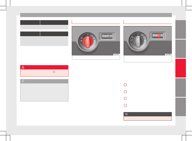
Fig. 129 

Instrument panel: light control.

Switching on side lights

Turn the light switch 

››› 

Fig. 129

 to position

.

Switching on dipped beam

Turn the light switch 

››› 

Fig. 129

 to position

.

Switching off lights (except daytime driving
lights)

Turn the light switch 

››› 

Fig. 129

 to position

0.

Main light range control 

Fig. 130 

Instrument panel: light range con-

trol.

Turn the control 

››› 

Fig. 130

 to set the lights

to the required setting.

Positions
The control positions roughly correspond to
the following vehicle load conditions.

Two front occupants, luggage compart-
ment empty.
All seats occupied, luggage compartment
empty.
All seats occupied, luggage compartment
fully loaded.
Driver only, luggage compartment fully
loaded.

CAUTION

Always adjust the range of the lights so that:

»

-

1

2

3

117

Tec

hnic

al

 d

at

a

Adv

ic

e

Oper

ation

Emer

genc

ie

s

Saf

ety

-------------------------------------------------------------------------------------------------------------------------------------------------------------

-------------------------------------------------------------------------------------------------------------------------------------------------------------

Operation

Your vehicle does not dazzle others, partic-

ularly oncoming traffic

The range of the headlights is sufficient for

safe driving

Note

Make sure you set the range of the main
lights when the dipped beam headlights are
switched on.

Daytime running lights

Daytime running lights are signalling devices
for improving road safety. The lights are built
into the headlights and come on each time
the ignition is turned on if the light switch is
in position 

0 or  

››› 

Fig. 129

. It is automat-

ically switched off when the side lights are
turned on.

Switching the daytime driving lights on

Remove the key from the ignition, move the

turn signal lever upward (right turn signal),
press it back to flash position and hold it
there.

Insert the key and switch on the ignition,

holding it in this position for 3 seconds.
Then, switch off the ignition. The daytime
running light is now activated and the corre-
sponding lights can come on.

Switching the daytime running light off

Remove the key from the ignition, press the

turn signal lever down (left turn signal), press
it back to flash position and hold it here.

Insert the key and switch on the ignition,

holding it in this position for 3 seconds.
Then, switch off the ignition. The daytime
running light is now deactivated and the cor-
responding lights cannot come on.

OR: activate and deactivate the daytime
lights using the Easy Connect system

››› 

page 21

.

Automatic control of the dipped beam in
combination with the daytime running lights
If the dipped beam control and the daytime
running lights
 are activated at the same
time, the dipped beams and the instrument
panel lighting will automatically come on as
required (e.g. when entering a tunnel) and
the daytime running lights will switch off.
When the automatic dipped beam control
switches off the dipped beams (e.g. when
coming out of a tunnel), the daytime running
lights come back on.

WARNING

The rear lights do not come on with the day-
time driving light. A vehicle which does not
have the rear lights on may not be visible to
other drivers in the darkness, if it is raining
or in conditions of poor visibility.

Note

Please observe any relevant legal require-
ments which may apply in your country.

Turn signal and main beam lever

Fig. 131 

Turn signal and main beam lever.

The turn signal and main beam lever also op-
erates the parking lights and the headlight
flasher.

Right and left-hand  turn signal 

Move the lever 

››› 

Fig. 131

 up 

1

 or down

2

.

Keep the lever held down at the point of re-

sistance for the turn signals to flash for as
long as you hold the lever, e.g. when chang-
ing lanes.

118

-------------------------------------------------------------------------------------------------------------------------------------------------------------

-------------------------------------------------------------------------------------------------------------------------------------------------------------

Lights and visibility

Convenience turn signals
For the convenience turn signals, move the
lever as far as possible upwards or down-
wards and release the lever. The turn signal
will flash three times.

The convenience turn signals are activated
and deactivated in the Easy Connect system
via the 



 key and the 

Setup

 function button

››› 

page 99

.

In vehicles that do not have the correspond-
ing menu, this function can be deactivated in
a specialised workshop.

Main beams 

Switch on the dipped beam 

››› 

page 117

.

Press the lever 

››› 

Fig. 131

 forward in the di-

rection indicated by arrow 

3

.

Pull the lever back to its original position in

the direction indicated by arrow 

4

 to switch

the main beam off.

Headlight flasher 

Pull the lever 

››› 

Fig. 131

 towards the steer-

ing wheel (point of resistance) in the direc-
tion indicated by arrow 

4

.

Parking lights 

Instructions for use 

››› 

page 121

.

CAUTION

Never use the main beam headlights or the
headlight flasher if they could dazzle other
drivers.

Note

If the convenience turn signals are operat-

ing (three flashes) and the other convenience
turn signals are switched on, the active part
stops flashing and only flashes once in the
new part selected.

The turn signals only work when the igni-

tion is switched on. The corresponding warn-
ing lamp 
 or  flashes in the general instru-
ment panel.

The turn signals switch off automatically

when the steering wheel is returned to the
straight-ahead position.

If a turn signal bulb is defective, the control

lamp flashes at double speed.

Automatic dipped beam control 

If the light switch is in this position 

››› 

Fig. 129

, the side lights, headlights and

the number plate lights will turn on or off au-
tomatically.

The light is adjusted according to the data re-
corded by the light sensor that is installed
between the windscreen and the inside rear
view mirror.

If the light switch is in position , the sym-
bol  located next to the light switch will il-
luminate. If the light illuminates automatical-
ly, symbol  located next to the light switch
will also illuminate.

Automatic headlights in case of rain
If the light switch is in position  and is
connected to the automatic wipe in case of
rain for more than 10 seconds or wipe (posi-
tion 

2

 or 

3

) for longer than 15 seconds,

››› 

page 125

 then the side lights and head-

lights will automatically switch on.

The light automatically switches off if more
than 4 minutes have elapsed and the auto-
matic wipe or wipe (position 

2

 or 

3

) have

not been switched on.

CAUTION

Do not cover the windscreen light sensor with
stickers or similar objects; this could impair
operation.

119

Tec

hnic

al

 d

at

a

Adv

ic

e

Oper

ation

Emer

genc

ie

s

Saf

ety

-------------------------------------------------------------------------------------------------------------------------------------------------------------

-------------------------------------------------------------------------------------------------------------------------------------------------------------

Operation

Front fog lights*

Fig. 132 

Instrument panel: light switch.

Switching on front fog lights

First turn the light switch 

››› 

Fig. 132

 to po-

sition ,  or .

Pull on the light switch to position 

1

.

The  warning lamp lights up on the general
instrument panel if the front fog lights are
switched on.

Front fog lights with cornering func-
tion*

3

 Not valid for vehicles fitted with Full-LED lights

Front fog lights with cornering function pro-
vide better lighting of the area around the car
when driving through a corner or parking,
etc.

Front fog lights with cornering function
switch on depending on how far you turn the
steering wheel or whether or not the turn sig-
nals

1)

 are switched on, if the following condi-

tions are met:

The vehicle is stationary, the ignition is

switched on or you are moving at a speed of
less than 40 km/h (25 mph);

The daytime driving light is switched off

The dipped beam is switched on

The fog lights are switched off

Reverse gear is not engaged

Rear fog light

Switching on the rear fog light

First turn the light switch 

››› 

Fig. 132

››› 

page 120

 to position ,  or .

Pull on the light switch to position 

2

.

If the vehicle is not equipped with front fog
lights 

››› 

page 120

, the rear fog light is

switched on by turning the switch to position

 or  and pulling it to position 

2

. This

type of switch only has one position.

The  

››› 

page 98

 warning lamp lights up on

the general instrument panel if the rear fog
lights are switched on.

If you are towing a trailer or caravan equip-
ped with a rear fog light on a vehicle with a
factory-fitted towing bracket or one installed
using parts from the original SEAT parts
catalogue
, only the rear fog light on the trail-
er or caravan will light up.

1)

In the event of a conflict between both functions,

i.e. if you turn the steering wheel to the left while the
right-hand turn signal is on, the turn signals will take
priority.

120

-------------------------------------------------------------------------------------------------------------------------------------------------------------

-------------------------------------------------------------------------------------------------------------------------------------------------------------

Lights and visibility

Function “Coming Home”/“Leaving
Home”*

This function makes it possible, under poor
visibility conditions, to automatically turn on
the lights for a brief period of time after the
vehicle has been parked or when approach-
ing the vehicle.

The function is automatically turned on if the
following conditions are met:

The light switch is in position 

››› 

page 119

.

The visibility around the vehicle is reduced.

The ignition is switched off.

To turn on this function, switch on the head-
light flasher prior to exiting the vehicle.

The light is adjusted according to the data re-
corded by the light sensor that is installed
between the windscreen and the inside rear
view mirror.

The function automatically turns on the side
lights and headlights, the lighting for the en-
try area on the exterior mirrors and the num-
ber plate light.

“Coming Home” function
The light is automatically switched on when
the driver door is opened (for 60 seconds af-
ter the ignition is switched off).

The lights is switched off when all the doors
and the boot lid are closed.

If a door or the boot lid remains open, the
light will switch off after 60 seconds.

“Leaving Home” function
The light is automatically switched on when
the vehicle is unlocked using the remote con-
trol.

The light is switched off after 10 seconds or
when the vehicle is locked.

Hazard warning lights switch

Fig. 133 

Instrument panel: switch for hazard

warning lights.

Press the button  

››› 

Fig. 133

 to switch

the hazard warning lights on or off.

The warning lamps on the instrument panel
and the warning lamp on the switch will flash

at the same time as the turn signals when
the hazard warning lights are switched on.
The hazard warning lights also work when
the ignition is switched off.

The hazard warning lights come on automati-
cally in the event of an accident in which an
airbag is triggered.

Note

Switch on the hazard warning lights to warn
other road users, for example:

When reaching the tail end of a traffic jam

if the vehicle has a technical fault or you

are involved in an emergency situation.

Parking lights*

Parking lights 

Switch the ignition off.

Move the turn signal lever 

››› 

Fig. 131

››› 

page 118

 up or down to turn on the right

or left-hand parking lights respectively.

Parking light on both sides

Turn the light switch 

››› 

Fig. 129

 

››› 

page 117

 to position  and engage the

steering lock.

»

121

Tec

hnic

al

 d

at

a

Adv

ic

e

Oper

ation

Emer

genc

ie

s

Saf

ety

-------------------------------------------------------------------------------------------------------------------------------------------------------------

-------------------------------------------------------------------------------------------------------------------------------------------------------------

Operation

Note

The parking lights  can only be activated

with the ignition disconnected.

The parking light will not come on automat-

ically after switching off the ignition if the
left- or right-hand turn signal is left on.

Adjusting the headlights

The light beam of the dipped beam lights is
asymmetric: the side of the road on which
you are driving is lit more intensely.

When a car that is manufactured in a country
that drives on the right travels to a country
that drives on the left (or vice versa), it is nor-
mally necessary to cover part of the headlight
bulbs with stickers or to change the adjust-
ment of the headlights to avoid dazzling oth-
er drivers.

In such cases, the regulations specify certain
light values that must be complied with for
designated points of the light distribution.
This is known as “Tourist light”.

The light distribution of the halogen and full-
LED headlights of the SEAT Toledo allows the
specific “tourist light” values to be met with-
out the need for stickers or changes in the
settings.

Note

“Tourist light” is only allowed temporarily. If
you are planning a long stay in a country that
drives on the other side, you should take the
vehicle to an Authorised Technical Service to
change the headlights.

Interior lights

Interior lighting

Fig. 134 

Interior lighting – version 1.

Fig. 135 

Interior lighting – version 2.

Read the additional information carefully

››› 

page 20

Where the courtesy light is on (switch 

A

››› 

Fig. 134

 in position ), the light will come

on if:

the vehicle is unlocked,

one of the doors is opened,

The key is removed from the ignition

When the courtesy light is on (switch 

A

 in

position ), the light will switch off if:

the vehicle is locked,

the ignition is switched on,

30 seconds after all of the doors have been

closed

If a door is left open or if switch 

A

 is in the

 position, the interior lighting switches off

after about 10 minutes to prevent the battery
from running flat.

122

-------------------------------------------------------------------------------------------------------------------------------------------------------------

-------------------------------------------------------------------------------------------------------------------------------------------------------------

Lights and visibility

Rear interior light

Fig. 136 

Rear interior light.

Press the button 

››› 

Fig. 136

 to switch the

lighting on or off.

Interior lights / ambient light*

The lighting in the central console area, the
door handles, the storage pockets in the
front doors, the footwell area and the instru-
ment panel trim will switch on fully when the
doors are opened and will decrease in inten-
sity while driving with the dipped beam
headlights on.

The intensity of the ambient light* can be ad-
justed using the menu 

Easy Connect >

Lighting settings > Vehicle inte-
rior lighting


››› 

page 21

.

Glove box light

The light will come on automatically when
the glove compartment is opened. The light
will go out when the glove compartment is
closed.

Luggage compartment light

The light switches on automatically when the
boot is open and switches off automatically
10 minutes after the boot lid has been
opened.

Visibility

Heated rear window

Fig. 137 

Heated rear window switch.

Switch the heated rear window on or off by
pressing the button 


››› 

Fig. 137

, the

warning lamp in the button will come on or
go off respectively.

The heated rear window only works when the
engine is running.

After approximately 7 minutes, the heating
device of the rear window 

switches off auto-

matically.

For the sake of the environment

The heated rear window should be switched
off as soon as the glass is demisted. By sav-
ing electrical power you can also save fuel

››› 

page 162

.

Note

In the event of a drop in voltage in the on-
board systems, the heated rear window
switches off automatically to ensure enough
power to control the engine 

››› 

page 214, Au-

tomatic disconnection of electrical equip-
ment

.

123

Tec

hnic

al

 d

at

a

Adv

ic

e

Oper

ation

Emer

genc

ie

s

Saf

ety

-------------------------------------------------------------------------------------------------------------------------------------------------------------

-------------------------------------------------------------------------------------------------------------------------------------------------------------

Operation

Sun visors

Fig. 138 

Driver's sun visor.

Fig. 139 

Front passenger's sun visor.

The sun visors for the driver and the front
passenger can be pulled out of their central
supports and turned towards the doors in the
direction of arrow 

1


››› 

Fig. 138

 and 

2

››› 

Fig. 139

 respectively.

The strip 

A

 is to store small objects such as

notepaper, etc.

The front passenger sun visor includes a van-
ity mirror 

B

 with a cover. The cover is

opened by sliding it in the direction indicated
by arrow 

3


››› 

Fig. 139

.

WARNING

Do not turn sun visors with attached objects
such as ball-pens, etc. toward the head pro-
tection airbag triggering zone on the side
windows. The head protection airbags could
injure occupants if triggered.

Windscreen wipers and wind-
screen washers

Introduction

The windscreen wipers and windscreen
washers only work when the ignition is
switched on.

The speed of the automatic wipe in case of
rain is automatically adjusted according to
the intensity of the rainfall.

The rear window is wiped once if the wind-
screen wipers are switched on and reverse
gear is engaged.

Fill the windscreen washer fluid 

››› 

page 210

.

WARNING

Make sure the blades 

››› 

page 53

 are in

perfect condition for good visibility and safe
driving.

In cold conditions, you should not use the

wash/wipe system unless you have warmed
the windscreen with the heating and ventila-
tion system. The windscreen washer fluid
could otherwise freeze on the windscreen and
obscure your view of the road.

CAUTION

During winter, always check that the wind-

screen wiper blades are not frozen to the
glass before each trip or before switching on
the ignition. If you switch on the windscreen
wipers when the wiper blades are frozen to
the glass, this could damage both the wiper
blades and the wiper motor.

If the ignition is switched off when the

windscreen wipers are on, they will start op-
erating in the same mode when the ignition
is switched back on. The wiper blades may be
frozen to the glass at low temperatures when
the ignition is switched off.

Carefully separate the frozen wipers from

the windscreen or rear window.

Remove snow and ice from the wipers be-

fore starting your journey.

Careless handling could lead to the wiper

arms damaging the windscreen.

124

-------------------------------------------------------------------------------------------------------------------------------------------------------------

-------------------------------------------------------------------------------------------------------------------------------------------------------------

Lights and visibility

For safety reasons, the wiper blades should

be changed once or twice a year. They can be
purchased at a SEAT Authorised Service.

The ignition cannot be switched on while

the windscreen wiper arms are in a raised po-
sition. Otherwise, the windscreen wipers
would return to their original position and
could damage the paintwork on the bonnet.

Note

Keep the wipers clean. The wipers can be
soiled with remains of wax solutions from car
washes 

››› 

page 194

.

On vehicles equipped with windscreen

washer jets, these are heated once the en-
gine is running.

Operating windscreen wipers and
washers

Fig. 140 

Window wiper lever.

Short wipe

Give the windscreen a 

brief wipe by moving

the lever down to position 

4


››› 

Fig. 140

.

Wipe intervals/automatic wipe in case of rain
rain sensor*

Push the lever up to position 

1

››› 

Fig. 140

.

With switch 

A

, adjust the wipe interval or

rain sensor sensitivity.

Switch 

A

 has 4 positions.

The rain sensor* is part of the intermittent
wipe function.

The rain sensor* controls the frequency of
the windscreen wiper intervals, depending
on the amount of rain.

Slow wipe

Push the lever up to position 

2

››› 

Fig. 140

.

Continuous wipe

Push the lever up to position 

3

››› 

Fig. 140

.

Automatic windscreen wash and wipe

Pull the lever towards the steering wheel,
position 

5


››› 

Fig. 140

, and the windscreen

washer and wipers are switched on.

Release the lever. The washer will stop and
the windscreen wipers will keep running for
1-3 wipes (depending on the windscreen
washer operating time).

Rear window wiper*

Press the lever forward to position 

6

››› 

Fig. 140

 and the rear window wiper will

run every 6 seconds.

Automatic rear window wash and wipe*

Press the lever fully forward to position 

7

››› 

Fig. 140

 and the rear window wiper and

washer switch on at the same time.

Release the lever. The rear window washer
will stop and the rear window wipers will
keep running for 1-3 wipes (depending on
the jet operating time). 

When released, the

lever remains in position 

6

.

Switching off the wipers

Move the lever to position 

0


››› 

Fig. 140

.

WARNING

The rain sensor may not detect enough rain
to switch on the wipers.

If necessary, switch on the wipers manually

when water on the windscreen obstructs visi-
bility.

»

125

Tec

hnic

al

 d

at

a

Adv

ic

e

Oper

ation

Emer

genc

ie

s

Saf

ety

-------------------------------------------------------------------------------------------------------------------------------------------------------------

-------------------------------------------------------------------------------------------------------------------------------------------------------------

Operation

Note

Do not put stickers on the windscreen in front
of the rain sensor*. This may cause sensor
disruption or faults.

Headlight washers*

The headlight washers operate briefly if the
dipped headlights or headlights are on and
the lever is moved to position 

5


››› 

Fig. 140

.

The headlight washer system also operates
every 10 windscreen wash cycles.

Clean off stubborn dirt (insects, etc.) from the
headlights at regular intervals, for instance
when filling the fuel tank. Please observe the
following indications 

››› 

page 196, Head-

lights

.

To ensure the system works properly in win-
ter, keep the nozzle holders free of snow and
remove any ice with a de-icer spray.

CAUTION

Never pull on the nozzle holders. Risk of
damage to the system!

Mirrors

Rear view mirror with manual anti-
dazzle device

Basic settings

Push the lever at the bottom of the mirror
forward.

Rear vision mirror anti-dazzle setting

Pull the lever at the bottom of the mirror to-
wards you.

Exterior mirrors

Read the additional information carefully

››› 

page 13

Before beginning any journey, adjust the rear
view mirrors for a good rear visibility.

WARNING

Convex (wide-angle) rear vision mirrors give

a larger field of vision. However, they make
objects appear smaller and further away than
they really are. For this reason, you should
not rely on these rear vision mirrors for judg-
ing the distance of vehicle behind.

If possible, use the interior rear vision mir-

ror to estimate distances to vehicles behind
you.

Note

Exterior mirrors are only heated when the

engine is running.

Do not touch the exterior mirrors when the

heating system is running.

If the electrical adjustment should ever fail

to operate, the rear vision mirrors can be ad-
justed by hand by pressing the edge of the
mirror glass.

Visit the technical service in the event of a

fault in the electrical rear vision mirror ad-
justment system.

126

-------------------------------------------------------------------------------------------------------------------------------------------------------------

-------------------------------------------------------------------------------------------------------------------------------------------------------------

Seats and head restraints

Seats and head restraints

Adjusting seats and head re-
straints

Introduction

Read the additional information carefully

››› 

page 11

Set the driver seat in such a way that the
pedals can be fully depressed with your legs
slightly bent.

Set the driver seat backrest so that you can
reach the upper point of the steering wheel
with your arms slightly bent.

The correct seat position is very important
for:

reaching all of the controls safely and

quickly,

a relaxed posture that will not produce fati-

gue,

maximum protection from the seat belts

and airbag system

WARNING

Adjust the driver seat only when the vehi-

cle is stationary. Risk of accident!

Be careful when adjusting the front seats!

Careless and uncontrolled adjustment can
cause injuries.

The backrests must not be reclined too far

back while driving. This could limit the effect
of the seat belts and the airbag system. Risk
of injury!

Never transport more than the permitted

amount of people in your vehicle.

Every occupant in the vehicle must properly

fasten and wear the seat belt belonging to
his or her seat. Children must be protected
with an appropriate child restraint system

››› 

page 72, Transporting children safely

.

The front seats, head restraints and seat

belts must always be adjusted to the size of
the vehicle occupant to provide you and your
passengers with the greatest possible protec-
tion.

Your feet should remain in the footwell

while the vehicle is moving; never rest them
on the dash panel, on the window or on the
seat! This also applies to passengers. An in-
correct sitting position exposes you to an in-
creased risk of injury in case of a sudden
braking or an accident. If the airbag is trig-
gered, you could sustain severe injuries due
to an incorrect sitting position!

It is important for the driver and front pas-

senger to keep a distance of at least 25 cm
from the steering wheel and dash panel. Fail-
ure to respect the minimum distance means
that the airbag will not protect you. Risk of
fatal injury if triggered!

Objects must not be placed in the footwell,

as they could move to the area of the pedals
in the event of a braking manoeuvre or
change of direction. This would prevent the

clutch, brake or accelerator from being press-
ed.

Do not place any items on the front passen-

ger seat other than those allowed (e.g. child
seat). Risk of accident!

Note

After a certain time, the backrest angle ad-
justment mechanism may gain a certain
amount of play.

127

Tec

hnic

al

 d

at

a

Adv

ic

e

Oper

ation

Emer

genc

ie

s

Saf

ety

-------------------------------------------------------------------------------------------------------------------------------------------------------------

-------------------------------------------------------------------------------------------------------------------------------------------------------------

Operation

head restraints

Fig. 141 

Front head restraint: adjust or re-

move.

Fig. 142 

Rear centre head restraint: release

point.

Read the additional information carefully

››› 

page 12

Head restraints cannot be moved up or down
or removed on sports seats.

Fitting and removing head restraints on front
seats

Push the head restraint up as far as it will
go.

Press catch 

1


››› 

Fig. 141

 and remove the

head restraint.

To refit, insert the head restraint into the
holes in the backrest, pushing it down until
it engages.

Fitting and removing head restraints on rear
seats
To remove the head restraint, the correspond-
ing backrest must be partially folded forward.

Unlock the backrest 

››› 

page 130

Move the head restraint upwards until it ar-
rives to the top.

Press button 

1


››› 

Fig. 142

, while simulta-

neously pressing on the security hole 

2

››› 

Fig. 142

 with a flat screwdriver a maxi-

mum of 5 mm wide, and remove the head
restraint.

To refit, insert the head restraint into the
holes in the backrest, pushing it down until
it engages.

For maximum head restraint protection, ad-
just the head restraint so that its upper edge
is at the same level as the top of your head.

The head restraint must be adjusted in line
with the height of users. Correct adjustment
of the head restraint, together with the seat
belts, ensure effective passenger protection

››› 

page 56

.

WARNING

Badly adjusted head restraints increase the

risk of injuries in the event of an accident.

Never drive with the head restraints re-

moved. Risk of injuries!

If the seats are in use, never drive with the

rear head restraints in their out-of-use posi-
tion.

Seat functions

Heated front seats*

Fig. 143 

Heated front seats.

128

-------------------------------------------------------------------------------------------------------------------------------------------------------------

-------------------------------------------------------------------------------------------------------------------------------------------------------------

Seats and head restraints

The cushion and backrest of the front seats
can be heated electrically.

Press the 

 or 


››› 

Fig. 143

 button to switch

on and adjust the heated front seats.

Press once to connect the heating at maxi-
mum force.

Press the button again to reduce the force of
the heating and switch it off. The force is indi-
cated by the number of warning lamps lit on
the button.

WARNING

Do not use the heated seat if your perception
of pain and/or temperature or that of your
passenger is limited, e.g. due to medication,
paralysis or chronic illness (e.g. diabetes). It
could cause burns on the back, buttocks and
legs that are difficult to heal. If you still want
to use the heated seat, take frequent breaks
on long journeys so that the body can recover
from the trip. Ask your doctor about your par-
ticular situation.

CAUTION

To avoid damaging the heating elements,

do not kneel on the seat or apply sharp pres-
sure at a single point to the seat cushion or
backrest.

Do not use the heated seats if nobody is

sitting on them or if there are items attached
to or lying on them, such as a child seat or a

bag, etc. This could lead to a fault in the seat
heating elements.

Do not clean the seats with anything damp

››› 

page 198

.

Note

Only connect the heated seats when the

engine is running. This provides considerable
savings on the battery capacity.

In the event of a drop in voltage in the on-

board systems, the heated seats switch off
automatically to ensure enough power to con-
trol the engine 

››› 

page 214, Automatic dis-

connection of electrical equipment

.

Armrest on front seats with inner stor-
age*

Fig. 144 

Armrest/Opening and closing the

storage compartment.

Adjusting armrest height

Lift the armrest as far as it will go and then
fold it downward.

»

129

Tec

hnic

al

 d

at

a

Adv

ic

e

Oper

ation

Emer

genc

ie

s

Saf

ety

-------------------------------------------------------------------------------------------------------------------------------------------------------------

-------------------------------------------------------------------------------------------------------------------------------------------------------------

Operation

Raise the armrest until it engages in one of
the 5 positions.

Opening storage compartment

Press the button located on the front of the
armrest 

››› 

Fig. 144

 - .

Lift the storage compartment lid 

››› 

Fig. 144

- .

Armrest on rear seats

Fig. 145 

Rear seats: armrest.

The armrest can be folded away for greater
comfort using the handle 

››› 

Fig. 145

.

Folding down the backrest

Fig. 146 

Unlocking the backrest.

Folding

Before folding the rear seats, adjust the po-
sition of the front seats so that the rear
seats are not damaged. When the front
seats are adjusted to the rear position,
their head restraints should be removed
before folding the backrests on the rear
seats. Store the removed head restraints in

such a way that they cannot be soiled or
damaged.

Insert the seat belt latch plate into hole 

A

››› 

Fig. 146

 located on the corresponding

side of the vehicle – safety position.

Press the lock button 

B

 to unlock the

backrest and fold it forward.

Returning to the initial position

Where the head restraint has been re-
moved, insert it into the backrest when par-
tially raised.

Push the backrest backwards to its original
position until the lock button engages –
check that it is locked by pulling on the
backrest 

››› 

.

Make sure the red protruding part 

C

 is not

visible.

WARNING

Once the backrests have been lifted, the

seat belts and their buckles must be in their
initial position – ready for use.

The backrests must be safely locked to en-

sure any items in the boot cannot move
around the interior of the vehicle in the event
of a sudden braking manoeuvre. Risk of inju-
ries!

Make sure the rear backrests are correctly

locked. Only then will the three-point auto-
matic seat belt on the rear central seat work
correctly.

130

-------------------------------------------------------------------------------------------------------------------------------------------------------------

-------------------------------------------------------------------------------------------------------------------------------------------------------------

Transport and practical equipment

CAUTION

Take care when handling the rear backrests
so as not to damage the seat belts. The seat
belt must never be left behind the lifted back-
rest.

Transport and practical
equipment

Practical equipment

Passenger side storage compartment

Fig. 147 

Instrument panel: passenger side

glove compartment.

Fig. 148 

Storage: cooling control.

Opening and closing passenger side glove
compartment

Pull the catch on the lid in the direction in-
dicated by the arrow 

››› 

Fig. 147

 and open

the lid.

Close the lid and push it until it engages.

Depending on the vehicle equipment, the CD
player is located in the glove compartment.
Separate operating instructions are enclosed
for this equipment in the corresponding In-
struction Manual.

Glove compartment cooling*
Open or close the air outlet by turning the
thumbwheel 

››› 

Fig. 148

.

If the air outlet is open and the air condition-
ing is on, the cooled air will be released into
the glove compartment.

If the air outlet is open and the air condition-
ing is off, outdoor air (not conditioned) will
be released into the glove compartment.

The air outlet should be closed if the air con-
ditioning is being used in heating mode or
where glove compartment cooling is not in
use.

WARNING

For safety reasons, all storage compart-

ments must be closed while the vehicle is
moving.

»

131

Tec

hnic

al

 d

at

a

Adv

ic

e

Oper

ation

Emer

genc

ie

s

Saf

ety

-------------------------------------------------------------------------------------------------------------------------------------------------------------

-------------------------------------------------------------------------------------------------------------------------------------------------------------

Operation

Never place any objects on the instrument

panel. These objects could be flown around
the interior while the vehicle is moving (on
accelerating or turning) and distract you. Risk
of accident!

Make sure objects remain in the centre con-

sole or other compartments while the vehicle
is moving. Otherwise, this could prevent you
from braking, changing gear or accelerating.
Risk of accident!

Note

The glove compartment can hold a bottle no
larger than 1 litre.

Storage compartment for reflective
vest

Fig. 149 

Driver's seat: storage compartment

There is a compartment below the driver seat

››› 

Fig. 149

 to store the reflective vests.

WARNING

The compartment is solely designed to store
the reflective vest and no other objects. Ob-
jects falling out of the storage compartment
could limit or prevent use of the pedals.

CAUTION

The compartment is solely designed to store
the reflective vest and no other objects, since
there is a risk of damaging the storage com-
partment.

Storage pocket under the front seats

There is a storage pocket on the rear part of
the backrest of the front seats.

These pockets are designed to hold maps,
magazines, etc.

WARNING

Do not place heavy objects in the pockets.
Risk of injury!

CAUTION

Do not place overly large objects in the pock-
ets (e.g. bottles) or objects with sharp edges.
Risk of damage to the pockets and the up-
holstery.

Drink holder in the centre console

Fig. 150 

Centre console: drink holder

Front drink holder in the centre console
Rear drink holder in the centre console

WARNING

Do not put hot drinks in the drink holders.

They could spill while the vehicle is moving.
Risk of scalding!

A

B

132

-------------------------------------------------------------------------------------------------------------------------------------------------------------


Content      ..     6      7      8      9     ..