Seat Toledo. Service Manual - part 1


  Index      Seat     Seat Toledo. Service Manual


Search            copyright infringement  


Content      ..       1      2      ..


Seat Toledo. Service Manual - part 1


-------------------------------------------------------------------------------------------------------------------------------------------------------------

The essentials

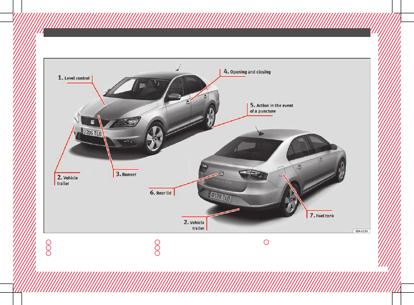
Exterior view

1


››› 

page 39

2


››› 

page 50

3


››› 

page 11

4


››› 

page 9

5


››› 

page 44

6


››› 

page 10

7


››› 

page 39

5

-------------------------------------------------------------------------------------------------------------------------------------------------------------

-------------------------------------------------------------------------------------------------------------------------------------------------------------

The essentials

Exterior view

1


››› 

page 40

2


››› 

page 40

3


››› 

page 43

4


››› 

page 41

5


››› 

page 40

6


››› 

page 41

7


››› 

page 41

8


››› 

page 75

9


››› 

page 45

10


››› 

page 137

6

-------------------------------------------------------------------------------------------------------------------------------------------------------------

-------------------------------------------------------------------------------------------------------------------------------------------------------------

The essentials

Interior view (left-hand drive)

1


››› 

page 13

2


››› 

page 18

3


››› 

page 19

4


››› 

page 31

5


››› 

page 32

6


››› 

page 20

7


››› 

page 23

8


››› 

page 19

9


››› 

page 21

10


››› 

page 14

11


››› 

page 36

12


››› 

page 18

13


››› 

page 34

14


››› 

page 11

15


››› 

page 11

16


››› 

page 43

17


››› 

page 11

18


››› 

page 12

19


››› 

page 13

7

-------------------------------------------------------------------------------------------------------------------------------------------------------------

-------------------------------------------------------------------------------------------------------------------------------------------------------------

The essentials

Interior view (right-hand drive)

1


››› 

page 19

2


››› 

page 31

3


››› 

page 19

4


››› 

page 21

5


››› 

page 20

6


››› 

page 23

7


››› 

page 32

8


››› 

page 18

9


››› 

page 13

10


››› 

page 14

11


››› 

page 36

12


››› 

page 11

13


››› 

page 34

14


››› 

page 13

15


››› 

page 11

16


››› 

page 12

17


››› 

page 18

18


››› 

page 43

19


››› 

page 11

8

-------------------------------------------------------------------------------------------------------------------------------------------------------------

-------------------------------------------------------------------------------------------------------------------------------------------------------------

The essentials

How it works

Unlocking and locking

Doors

Fig. 1 

Remote control key: buttons.

Fig. 2 

Centre console: central locking switch.

Locking and unlocking the vehicle using the
key

Locking: press the  

››› 

Fig. 1

 button.

Unlocking: press the  

››› 

Fig. 1

 button.

Unlocking the rear lid: press the 

››› 

Fig. 1

 button until all the turn signals on

the vehicle briefly light up.

Locking and unlocking with the central lock-
ing switch

Locking: press the  

››› 

Fig. 2

 button. The

warning lamp on the button will light up.
None of the doors can be opened from the
outside. The doors can be opened from the
inside by pulling the inside door handle.

Unlocking: press the  

››› 

Fig. 2

 button. The

warning lamp on the button will switch off.

››› 

 in Unlocking and locking the vehicle

on page 105

››› 

page 104

››› 

page 9

››› 

page 10

Unlocking and locking the driver's
door

Fig. 3 

Driver door lever: hidden lock cylinder.

If the central locking system should fail to op-
erate, the driver door can still be locked and
unlocked by turning the key in the lock.

Unfold the vehicle key shaft.

Insert the key shaft into the lower opening

in the cover on the driver door handle from
below 

››› 

Fig. 3

 (arrow) then remove the cover

upwards.

Insert the key blade into the lock cylinder

to unlock or lock the vehicle.

Special Characteristics

The anti-theft alarm will remain active when

vehicles are unlocked. However, it is not trig-
gered 

››› 

page 107

.

»

9

-------------------------------------------------------------------------------------------------------------------------------------------------------------

-------------------------------------------------------------------------------------------------------------------------------------------------------------

The essentials

After the driver door is opened, you have

15 seconds to switch on the ignition. Once
this time has elapsed, the alarm is triggered.

Switch the ignition on. The electronic im-

mobilizer recognises a valid vehicle key and
deactivates the anti-theft alarm system.

Note

The anti-theft alarm is not activated when the
vehicle is locked manually using the key
shaft 

››› 

page 107

.

Locking manually

Fig. 4 

Rear door: manual locking

On the front of a door with no lock cylinder
there is an emergency locking device that is
only visible when the door is open.

Locking

Remove the cap 

A


››› 

Fig. 4

.

Insert the key in the slot 

B

 and turn it in

the direction of the arrow until horizontal (on
the other direction on the right-hand door).

Replace the cap.

Once the door has been locked, it can no lon-
ger be opened from the outside. The door
can be opened from the inside by pulling the
door handle.

Rear lid

Fig. 5 

Rear lid: opening from the outside.

Opening the rear lid: Pull on the release

lever and lift it up 

››› 

Fig. 5

. The rear lid opens

automatically.

Closing the rear lid: Hold it by one of the

handles on the interior lining and close it by
pushing gently.

››› 

 in Rear lid on page 114

››› 

page 113

››› 

page 10

Manual release of the rear lid

Fig. 6 

Luggage compartment: access to man-

ual release.

The rear lid can be unlocked manually from
inside in the event of an emergency.

Insert the key in the opening in the lining

of the rear lid and move the key in the direc-
tion of the arrow until the lock is released.

10

-------------------------------------------------------------------------------------------------------------------------------------------------------------

-------------------------------------------------------------------------------------------------------------------------------------------------------------

The essentials

Bonnet

Fig. 7 

Unlocking the bonnet.

Opening the bonnet: Pull the lever under

the dashboard 

››› 

Fig. 7


1

.

Lifting up the bonnet: press the release

catch under the bonnet upwards 

››› 

Fig. 7


2

.

The arrester hook under the bonnet is re-
leased.

The bonnet can be opened. Release the

bonnet stay and secure it in the fixture de-
signed for this in the bonnet.

››› 

 in Introduction on page 202

››› 

page 202

Electric windows*

Fig. 8 

Detail of the driver door: controls for

the windows.

Opening the window: Press the  button.

Closing the window: Pull the  button.

Buttons on the driver door

Window on the front left door
Window on the front right door
Window on the rear left door
Window on the rear right door
Safety switch for deactivating the electric
window buttons in the rear doors.

1

2

3

4

5

››› 

 in Operation of the electric windows

on page 115

››› 

page 115

Before driving

Manually adjusting the front seats

Fig. 9 

Front seats: manual seat adjustment.

Forward/back: pull the lever and move
the seat forwards or backwards.
Raising/lowering: pull/push the lever.
Tilting the backrest: pull the lever back.

››› 

 in Introduction on page 127

1

2

3

11

-------------------------------------------------------------------------------------------------------------------------------------------------------------

-------------------------------------------------------------------------------------------------------------------------------------------------------------

The essentials

Adjusting the head restraints

Fig. 10 

Front seat: adjustment of the head re-

straint.

Grab the sides of the head restraints with
both hands and push upwards to the desired
position. To lower it, repeat the same action,
pressing the 

1

 button on the side.

››› 

 in head restraints on page 128

››› 

page 59

››› 

page 128

Adjustment of the seat belt

Fig. 11 

Positioning and removing the seat

belt buckle.

Fig. 12 

Correct seat belt and head restraint

positions, viewed from front and the side.

To adjust the seat belt around your should-
ers, adjust the height of the seats.

The shoulder part of the seat belt should be
well centred over it, never over the neck. The
seat belt lies flat and fits comfortably on the
upper part of the body.

The lap part of the seat belt lies across the
pelvis, never across the stomach. The seat
belt lies flat and fits comfortably on the pel-
vis.

››› 

page 62

››› 

page 64

12

-------------------------------------------------------------------------------------------------------------------------------------------------------------

-------------------------------------------------------------------------------------------------------------------------------------------------------------

The essentials

Seat belt tensioners

During a collision, the seat belts on the front
seats are retracted automatically.

The tensioner can be triggered only once.

››› 

 in Service and disposal of belt ten-

sioners on page 66

››› 

page 65

Adjusting the exterior mirrors

Fig. 13 

Detail of the driver door: control for

the exterior mirror.

Adjusting the exterior mirrors: Turn the knob
to the corresponding position:

Turning the knob to the desired posi-
tion, adjust the mirrors on the driver

L/R

side (L, left) and the passenger side (R,
right) to the direction desired.
Depending on the equipment fitted on
the vehicle, the mirrors may be heated
according to the outside temperature.

››› 

 in Exterior mirrors on page 126

››› 

page 126

Adjusting the steering wheel

Fig. 14 

Lever in the lower left side of the

steering column.

Adjusting the position of the steering wheel:
Pull the 

››› 

Fig. 14


1

 lever down, move the

steering wheel to the desired position and lift
the lever back up until it locks.

››› 

 in Adjusting the steering wheel po-

sition on page 57

13

-------------------------------------------------------------------------------------------------------------------------------------------------------------

-------------------------------------------------------------------------------------------------------------------------------------------------------------

The essentials

Airbags

Front airbags

Fig. 15 

Driver airbag in the steering wheel

and front passenger airbag in the dash panel

Fig. 16 

Airbag covers reacting when the front

airbags are triggered.

The front airbag for the driver is located in
the steering wheel 

››› 

Fig. 15

  and the front

passenger airbag is located in the dash pan-
el 

››› 

Fig. 15

 . Airbags are identified by the

word “AIRBAG”.

When the driver and front passenger airbags
are deployed, the covers remain attached to
the steering wheel and dashboard, respec-
tively 

››› 

Fig. 16

.

In conjunction with the seat belts, the front
airbag system gives the driver and the front
passenger additional protection for the head
and chest in the event of a severe frontal col-
lision.

Their special design allows the controlled es-
cape of the propellant gas when an occupant
puts pressure on the bag. Thus, the head and
chest are protected by the airbag. After the
collision, the airbag deflates sufficiently to
allow visibility.

››› 

 in Front airbags on page 69

Deactivating the front passenger front
airbag

Fig. 17 

Front passenger front airbag switch.

14

-------------------------------------------------------------------------------------------------------------------------------------------------------------

-------------------------------------------------------------------------------------------------------------------------------------------------------------

The essentials

To deactivate the front passenger front air-
bag:

Open the glove compartment on the front

passenger side.

Insert the key blade into the slot provided

in the deactivation switch.

Approximately ¾ of the length of the key

blade remains inserted (the maximum).

Turn the key blade, changing its position to



. Do not force it. If you have difficulty, en-

sure that you have inserted the key as far as
it will go.

Finally, check the control lamp on the in-

strument panel where it shows  


   the following should appear .

››› 

 in Front passenger front airbag

switch on page 72

››› 

page 71

Side airbags*

Fig. 18 

Side airbag in driver's seat.

Fig. 19 

Illustration of completely inflated side

airbag on left side of vehicle.

The side airbags are located in the driver's
seat and front passenger seat backrests

››› 

Fig. 18

The locations are identified by the

text “AIRBAG” in the upper region of the
backrests.

In conjunction with the seat belts, the side
airbag system provides additional protection
for the upper body in the event of a severe
side collision 

››› 

page 61, The whys

and wherefores of seat belts

.

In a side collision, the side airbags reduce
the risk of injury to passengers to the areas
of the body facing the impact. In addition to
the normal protection from the front seat
belts, passengers are also held fast in the
event of a side collision, and this is how
these airbags provide maximum protection.

››› 

 in Side airbags* on page 69

15

-------------------------------------------------------------------------------------------------------------------------------------------------------------

-------------------------------------------------------------------------------------------------------------------------------------------------------------

The essentials

Head-protection airbags*

Fig. 20 

Location of head-protection airbags.

Fig. 21 

Deployed head-protection airbags.

The head-protection airbags are located on
both sides in the interior above the doors

››› 

Fig. 20

 and are identified with the text

“AIRBAG”.

In conjunction with the seat belts, the head-
protection airbag system gives the vehicle
occupants additional protection for the head

and upper body in the event of a severe side
collision 

››› 

page 15

.

››› 

 in Curtain airbags* on page 70

Child seats

Important information regarding the
front passenger's airbag

Fig. 22 

Passenger's side sun visor: airbag

sticker.

Fig. 23 

On the rear frame of the passenger

side door: airbag sticker.

A sticker with important information about
the passenger airbag is located on the pas-
senger's sun visor and/or on the passenger
side door frame.

››› 

 in Important information regarding

the front passenger's airbag on page 73

››› 

page 73

Possible ways to secure child seats

You can secure a child seat to the rear seat or
front passenger seat in the following ways:

Child seats in groups 

0 to 3 can be secured

with a seat belt.

16

-------------------------------------------------------------------------------------------------------------------------------------------------------------

-------------------------------------------------------------------------------------------------------------------------------------------------------------

The essentials

Child seats for groups 

0, 0+ and 1 can be

fastened without seatbelts, using the “ISO-
FIX” and Top Tether* system, using the “ISO-
FIX” and Top Tether* securing rings

››› 

page 17

.

Weight

group

Seat locations

Front pas-

senger

a)

Rear

outer

Rear

centre

Group 0
<10 kg

U*

U/L

U

Group 0+
<13 kg

U*

U/L

U

Group I
9-18 kg

U*

U/L

U

Group II/III
15-36 kg

U*

U

U

a)

Compliance with current national legislation and the manu-

facturer's instructions is required when using or installing child
seats.

Suitable for universal approved restrain-
ing systems for use in this age category
(universal retention systems are those
fitted using the adult seat belt).
Move the front passenger seat as far
back as possible, as high as possible
and always disable the airbag.
Suitable for retention systems using the
“ISOFIX” and Top Tether* anchors.

U:

*:

L:

The systems include the child restraint sys-
tem mounting with an upper retaining strap
(Top Tether) and lower anchoring points on
the seat.

››› 

 in Safety instructions on page 74

“ISOFIX” and Top Tether child seat
mounting system*

Fig. 24 

ISOFIX securing rings.

Fig. 25 

Top Tether* securing ring.

Child seats with the “ISOFIX” or Top Tether*
system can be secured quickly, easily and
safely on the rear outer seats.

When removing or fitting the child seat,
please be sure to follow the manufacturer's
instructions.

Move the rear seat as far to the rear as it

will go.

Press the child seat onto the “ISOFIX” re-

taining rings until the child seat can be heard
to engage. If the child seat is equipped with
Top Tether* anchor points, secure it to the
correspondent ring. Observe the manufactur-
er's instructions.

Pull on both sides of the child seat to en-

sure that it is secure.

Two “ISOFIX” retaining rings are fitted on
each rear seat. In some vehicles, the rings
are secured to the seat frame and, in others,
they are secured to the rear floor. Access to

»

17

-------------------------------------------------------------------------------------------------------------------------------------------------------------

-------------------------------------------------------------------------------------------------------------------------------------------------------------

The essentials

the “ISOFIX” rings is between the rear seat
backrest and the seat cushioning. The Top
Tether* rings are located at the rear of the
backrests of the rear seats (behind the seat
backrest or in the boot).

Child seats with the “ISOFIX” and Top Tether*
attachment system are available from Techni-
cal Services.

››› 

 in Safety instructions on page 74

Starting the vehicle

Ignition lock

Fig. 26 

Ignition key positions.

Switch ignition on: Place the key in the igni-
tion and start the engine.

Locking and unlocking the steering wheel

Engaging the steering wheel lock: Remove

the key from the ignition and turn the wheel
until it locks. In vehicles with an automatic
gearbox, the gear lever must be in the 

P posi-

tion in order to remove the key. If necessary,
press the locking key on the selector lever
and release it again.

Unlocking the steering wheel: Put the key

into the ignition and turn it at the same time
as the steering wheel in the direction indica-
ted by the arrow. If it is not possible to turn
the steering wheel, it may be because it is
locked.

Turning on/switching off the ignition, glow
plugs reheating

Switch ignition on: Turn the key to the 

2

position.

Switch ignition off. Turn the key to the 

1

position.

Diesel vehicles : The glow plugs reheat

when the ignition is switched on

Starting the engine

Manual gearbox: press the clutch pedal all

the way down and move the gearbox lever in-
to neutral.

Automatic gearbox: Press the brake pedal

and move the selector lever to the 

P position

or into 

N.

Turn the key to the 

3

 position. The key au-

tomatically returns to the 

2

 position. Do not

press the accelerator.

Start-Stop System*
When you stop and release the clutch pedal,
the Start-Stop system* turns off the engine.
The ignition remains switched on.

››› 

 in Introduction on page 149

››› 

page 149

Lights and visibility

Light switch

Fig. 27 

Dash panel: light control.

18

-------------------------------------------------------------------------------------------------------------------------------------------------------------

-------------------------------------------------------------------------------------------------------------------------------------------------------------

The essentials

Turn the switch to the required position

››› 

Fig. 27

.

Sym-

bol

Ignition switch-
ed off

Ignition is switch-
ed on

Fog lights, dipped
beam and side
lights off.

Light off or daytime
driving light on.



The “Coming home”
and “Leaving
home” guide lights
may be switched
on.

Automatic control of
dipped beam and day-
time running light.

Side light on.

Dipped beam head-
light off

Dipped beam switch-
ed on.

 Front fog lights: move the switch to the

first position, from positions ,  or .

 Rear fog light: move the switch completely

from positions ,  or .

Switching off fog lights: Push the switch or
turn it to the  position.

››› 

 in Introduction on page 116

››› 

page 116

Turn signal and main beam lever

Fig. 28 

Turn signal and main beam lever

More the lever to the required position:

Right turn signal: Right-hand parking
light (ignition switched off).
Left turn signal: Left-hand parking light
(ignition switched off).
Main beam switched on: Control lamp 
lit up on the instrument panel.
Headlight flasher: lit up when the lever is
pushed. Control lamp  lit up.

Lever all the way down to switch it off.

››› 

page 118

1

2

3

4

Hazard warning lights

Fig. 29 

Dash panel: switch for hazard warn-

ing lights.

Switched on, for example:

When approaching a traffic jam

In an emergency

The vehicle has broken down

When towing or being towed

››› 

page 121

19

-------------------------------------------------------------------------------------------------------------------------------------------------------------

-------------------------------------------------------------------------------------------------------------------------------------------------------------

The essentials

Interior lights

Fig. 30 

Detail of headliner: version 1

Fig. 31 

Detail of headliner: version 2

Knob

Function

Switches interior lights off.

Switches interior lights on.

Knob

Function

Switches door contact control on (central po-
sition).
The interior lights come on automatically
when the vehicle is unlocked, a door is
opened or the key is removed from the igni-
tion.
The lights go off a few seconds after all the
doors are closed, the vehicle is locked or the
ignition is switched on.

Turning the reading light on and off

››› 

page 122

Windscreen wipers and window wiper
blade

Fig. 32 

Operating the windscreen wiper and

rear wiper

More the lever to the required position:

0



Windscreen wiper off.

1

Windscreen wipers interval wipe.
Using the control 

››› 

Fig. 32


A

 adjust the

interval (vehicles without rain sensor), or
the sensitivity of the rain sensor.

2



Slow wipe.

3



Continuous wipe.

4



Short wipe. Brief press, short clean. Hold
the lever down for more time to increase
the wipe frequency.

5

Automatic wipe. The windscreen washer
function is activated by pushing the lever
forwards, and simultaneously the wind-
screen wipers start.

6

Interval wipe for rear window. The wiper
will wipe the window approximately every
six seconds.

7

The rear window wash function is activa-
ted by pressing the lever, and the rear wip-
er starts simultaneously.

››› 

 in Introduction on page 124

››› 

page 124

››› 

page 53

20

-------------------------------------------------------------------------------------------------------------------------------------------------------------


Content      ..       1      2     ..