Seat Leon. Service Manual - part 7


  Index      Seat     Seat Leon. Service Manual


Search            copyright infringement  


Content      ..     5      6      7      8     ..


Seat Leon. Service Manual - part 7


-------------------------------------------------------------------------------------------------------------------------------------------------------------
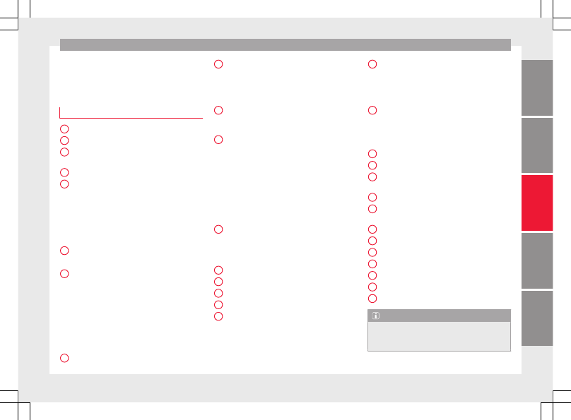
Controls and displays

Operation

Controls and displays

General instrument panel

Door release lever
Central locking switch

 . . . . . . . . . . . .

119

Electric control to adjust exterior
mirrors

 . . . . . . . . . . . . . . . . . . . . . . . . . . .

142

Air outlets

 . . . . . . . . . . . . . . . . . . . . . . . .

166

Control lever for:

Turn signals and main beam
headlights

 . . . . . . . . . . . . . . . . . . . . .

131

Lane Assist

 . . . . . . . . . . . . . . . . . . . . .

213

Main beam assist

 . . . . . . . . . . . . . . .

132

Cruise control system (CCS)

 . . . . .

195

Depending on equipment fitted:

Lever for cruise control

 . . . . . . . . . .

195

Steering wheel with horn and

Driver airbag

 . . . . . . . . . . . . . . . . . . .

16

On-board computer controls

 . . . .

30

Controls for radio, telephone,
navigation and speech dialogue
system 

››› 

Booklet Radio

Paddle levers for tiptronic gear-
shift (automatic gearbox)

 . . . . . . .

182

Instrument panel

 . . . . . . . . . . . . . . . . .

104

1

2

3

4

5

6

7

8

Control lever for:

Windscreen wipers and washer

 . .

139

Wipe and wash system

 . . . . . . . . . .

139

On-board computer

 . . . . . . . . . . . . .

30

Depending on equipment fitted: ra-
dio or display for Easy Connect
(navigation, radio, TV/video)

 . . . . . .

110

Depending on the equipment, but-
tons for:

SEAT driving modes

 . . . . . . . . . . . . .

219

Start-Stop system

 . . . . . . . . . . . . . . .

191

Park assist system

 . . . . . . . . . . . . . .

225

Hazard warning lights

 . . . . . . . . . .

135

Tyre pressure switch

 . . . . . . . . . . . .

277

Airbag off display

 . . . . . . . . . . . . . . .

81

Depending on the equipment,
glove compartment with:

 . . . . . . . . .

149

CD player* and/or SD card*

››› 

Booklet Radio

Tyre pressure switch

 . . . . . . . . . . . . . .

277

Front passenger airbag switch

 . . . .

81

Front passenger airbag

 . . . . . . . . . . .

16

Passenger seat heating control

 . . . .

145

Depending on the equipment, con-
trols for:

Heating and ventilation system or
manual air conditioner

 . . . . . . . . . .

48, 47

Automatic air conditioner

 . . . . . . .

45

9

10

11

12

13

14

15

16

17

Depending on the equipment:

USB/AUX-IN input

 . . . . . . . . . . . . . .

115

Connectivity Box*

 . . . . . . . . . . . . . . .

115

Storage compartment

Depending on equipment fitted,
gear lever or selector lever for:

Manual gearbox

 . . . . . . . . . . . . . . . .

179

Automatic gearbox

 . . . . . . . . . . . . .

180

Electronic parking brake switch

 . . .

172

Auto Hold switch

 . . . . . . . . . . . . . . . . .

194

Starter button (Keyless Access lock-
ing and ignition system)

 . . . . . . . . . .

169

Driver's seat heating control

 . . . . . .

145

Ignition lock (vehicles without Key-
less Access)

 . . . . . . . . . . . . . . . . . . . . . .

167

Knee airbag

 . . . . . . . . . . . . . . . . . . . . . .

17

Adjustable steering column

 . . . . . . .

16

Storage compartment
Bonnet lock release

 . . . . . . . . . . . . . . .

263

Headlight range control

 . . . . . . . . . . .

137

Headlight switch

 . . . . . . . . . . . . . . . . .

131

Electric windows

 . . . . . . . . . . . . . . . . .

127

Note

Some of the equipment listed in this sec-

tion is only fitted on certain models or are op-
tional extras.

»

18

19

20

21

22

23

24

25

26

27

28

29

30

31

103

Tec

hnic

al

 d

at

a

Adv

ic

e

Oper

ation

Emer

genc

ie

s

Saf

ety

-------------------------------------------------------------------------------------------------------------------------------------------------------------

-------------------------------------------------------------------------------------------------------------------------------------------------------------

Operation

A separate Instructions Manual is enclosed

if the vehicle is equipped with a factory-fitted
radio, CD player, AUX IN connection or navi-
gation system.

The arrangement of switches and controls

on right-hand drive models* may be slightly
different from the layout shown in

››› 

page 102

. However, the symbols used to

identify the controls are the same.

Instruments and warning/control lamps

Instruments

View of instrument panel

Fig. 120 

Instrument panel, on dash panel

Details of the instruments 

››› 

Fig. 120

:

Rev counter (with the engine running, in
hundreds of revolutions per minute).

1

The beginning of the red zone of the rev
counter indicates the maximum speed in
any gear after running-in and with the

104

-------------------------------------------------------------------------------------------------------------------------------------------------------------

-------------------------------------------------------------------------------------------------------------------------------------------------------------

Instruments and warning/control lamps

engine hot. However, it is advisable to
change up a gear or move the selector
lever to 

D (or lift your foot off the acceler-

ator) before the needle reaches the red
zone 

››› 

.

Engine coolant temperature display

››› 

page 107

 or 

the natural gas level indi-

cator in vehicles with natural gas engine
(CNG) 

››› 

page 108

.

Displays on the screen 

››› 

page 105

.

Adjuster button and display

››› 

page 107

.

Speedometer.
Fuel gauge 

››› 

page 108

.

WARNING

Any distraction may lead to an accident, with
the risk of injury.

Do not operate the instrument panel con-

trols when driving.

CAUTION

To prevent damage to the engine, the rev

counter needle should only remain in the red
zone for a short period of time.

When the engine is cold, avoid high revs

and heavy acceleration and do not make the
engine work hard.

2

3

4

5

6

For the sake of the environment

Changing up a gear in time reduces fuel con-
sumption and noise.

Rev counter

The rev counter indicates the number of en-
gine revolutions per minute 

››› 

Fig. 120


1

.

Together with the gear-change indicator, the
rev counter offers you the possibility of using
the engine of your vehicle at a suitable
speed.

The start of the red zone on the dial indicates
the maximum engine speed which may be
used briefly when the engine is warm and af-
ter it has been run in properly. Before reach-
ing this range, you should change to a higher
gear for vehicles with a manual gearbox or for
automatic gearboxes put the selector lever in
“D” or take your foot off the accelerator ped-
al.

We recommend that you avoid high revs and
that you follow the recommendations on the
gear-change indicator. Consult the additional
information in 

››› 

page 32, Gear-change

indicator

.

CAUTION

Never allow the rev counter needle 

1

››› 

Fig. 120

 to go into the red zone on the

scale for more than a very brief period, other-
wise there is a risk of engine damage.

For the sake of the environment

Changing up a gear early will help you to save
fuel and minimise emissions and engine
noise.

Indications on the display

A variety of information can be viewed on the
instrument panel display 

››› 

Fig. 120


3

, de-

pending on the vehicle equipment:

Bonnet, rear lid and doors open

››› 

page 33

.

Warning and information messages

››› 

page 33

.

Distance travelled 

››› 

page 107

.

Time 

››› 

page 106

.

Navigation instructions.

Outside temperature 

››› 

page 32

.

Compass 

››› 

page 106

.

Shift lever position 

››› 

page 180

.

Recommended gear (manual gearbox)

››› 

page 32

.

Multifunction display (MFD) and menus

with different setting options 

››› 

page 30

.

Service interval display 

››› 

page 37

.

»

105

Tec

hnic

al

 d

at

a

Adv

ic

e

Oper

ation

Emer

genc

ie

s

Saf

ety

-------------------------------------------------------------------------------------------------------------------------------------------------------------

-------------------------------------------------------------------------------------------------------------------------------------------------------------

Operation

Second speed display 

››› 

page 30

.

Speed warning function 

››› 

page 37

.

Start-Stop system status display

››› 

page 191

.

Active cylinder management display

(ACT

®

)* 

››› 

page 188

Signs recognised by the traffic signal de-

tection system 

››› 

page 222

Low consumption driving status (ECO)

››› 

page 106

Identifying letters on engine (MKB).

Distance travelled
The odometer registers the total distance
travelled by the car.

The odometer (

trip

) shows the distance

travelled since the last odometer reset. The
last digit of the trip recorder indicates distan-
ces of 100 metres or one tenths of a mile.

Briefly press the button 

››› 

Fig. 120


4

 to re-

set the trip recorder to 0.

Keep the button 

4

 pressed for about 3

seconds and the previous value will be dis-
played.

Time

To set the time, keep the button 

››› 

Fig. 120

4

 pressed for more than 3 seconds to select

the hour or minute display.

To continue setting the time, press the up-

per or lower part of the button 

4

. Hold but-

ton down to scroll through the numbers
quickly.

Press the button 

4

 again in order to finish

setting the time.

The time can also be set via the 



 button

and 

SETUP

 function button in the Easy Con-

nect system 

››› 

page 110

.

Compass
With the ignition on and the navigation sys-
tem on, the cardinal point corresponding to
the direction of travel of the vehicle is dis-
played on the instrument panel.

Selector lever position
The selected gear is displayed on the side of
the selector lever and on the instrument pan-
el display. In positions 

D and S, and with the

Tiptronic, the corresponding gear is also dis-
played.

Recommended gear (manual gearbox)
The recommended gear in order to save fuel
is displayed on the instrument panel while
you are driving 

››› 

page 32

.

Second speed display (mph or km/h)
In addition to the speedometer, the speed
can also be displayed in a different unit of
measurement (in miles or in km per hour).

This option cannot be deactivated in models
destined for countries in which the second
speed must always be visible.

The second speed display can be adjusted in
the Easy Connect system via the 



 button

and the 

SETUP

 function button 

››› 

page 110

.

Speed warning
When the speed setting is exceeded, this will
be indicated on the instrument panel display.
This is very useful, for example when using
winter tyres that are not designed for driving
at the maximum speed of the vehicle

››› 

page 37

.

The speed warning settings can be adjusted
in the Easy Connect system via the 



 button

and the 

SETUP

 function button 

››› 

page 110

.

Start-Stop operating display
Updated information relating to the status is
displayed on the instrument panel

››› 

page 191

.

Low consumption driving status (ECO)*
Depending on the equipment, when driving,
the “

ECO

” display appears on the instrument

panel when the vehicle is in low consump-
tion status due to active cylinder manage-
ment (ACT

®

)* 

››› 

page 188

.

106

-------------------------------------------------------------------------------------------------------------------------------------------------------------

-------------------------------------------------------------------------------------------------------------------------------------------------------------

Instruments and warning/control lamps

Identifying letters on engine (MKB)
Hold the button 

››› 

Fig. 120


4

 down for more

than 15 seconds to display the identifying
letters of the vehicle engine (MKB). To do
this, the ignition must be switched on and
the engine switched off.

WARNING

Observe the safety warnings 

››› 

 in Warning

and control lamps on page 109

.

WARNING

Even though outside temperatures are above
freezing, some roads and bridges may be icy.

At outside temperatures above +4°C

(+39°F), even when the “ice crystal symbol”
is not visible, there may still be patches of ice
on the road.

Do not rely on the outside temperature in-

dicator!

Note

Different versions of the instrument panel

are available and therefore the versions and
instructions on the display may vary. In the
case of displays without warning or informa-
tion texts, faults are indicated exclusively by
the warning lamps.

Depending on the equipment, some set-

tings and instructions can also be carried out
in the Easy Connect system.

When several warnings are active at the

same time, the symbols are shown succes-
sively for a few seconds and will stay on until
the fault is rectified.

Odometer

Fig. 121 

Instrument panel: odometer and re-

set button.

The distance covered is displayed in “kilome-
tres” or miles “m”. It is possible to change
the measurement units (kilometres
“km”/miles “m”) in the radio/Easy Connect*.
Please refer to the Easy Connect* Instructions
Manual for more details.

Odometer/trip recorder
The odometer shows the total distance cov-
ered by the vehicle.

The trip recorder shows the distance that has
been travelled since it was last reset. It is

used to measure short trips. The last digit of
the trip recorder indicates distances of 100
metres or tenths of a mile.

The trip recorder can be set to zero by press-
ing 

0.0/SET


››› 

Fig. 121

.

Fault display
If there is a fault in the instrument panel, the
letters 

DEF

 will appear in the trip recorder

display. Have the fault repaired immediately,
as far as is possible.

Coolant temperature gauge

For vehicles with no coolant temperature
gauge, a control lamp 

 appears for high

coolant temperatures 

››› 

page 266

. Please

note 

››› 

.

The coolant temperature gauge 

2

››› 

Fig. 120

 only works when the ignition is

switched on. In order to avoid engine dam-
age, please read the following notes for the
different temperature ranges.

Engine cold
If only the diodes in the lower part of the
scale light up, this indicates that the engine
has not yet reached operating temperature.
Avoid high revs and heavy acceleration and
do not make the engine work hard.

»

107

Tec

hnic

al

 d

at

a

Adv

ic

e

Oper

ation

Emer

genc

ie

s

Saf

ety

-------------------------------------------------------------------------------------------------------------------------------------------------------------

-------------------------------------------------------------------------------------------------------------------------------------------------------------

Operation

Normal temperature
If in normal operations, the diodes light up
until the central zone, it means that the en-
gine has reached operating temperature. At
high outside temperatures and when making
the engine work hard, the diodes may contin-
ue lighting up and reach the upper zone. This
is no cause for concern, provided the control
lamp 

 does not light up on the instrument

panel digital display.

Heat range
When the diodes light up in the upper area of
the display and the control lamp appears 

on the instrument panel display, the coolant
temperature is excessive 

››› 

page 266

.

CAUTION

To ensure a long useful life for the engine,

avoid high revs, driving at high speed and
making the engine work hard for approxi-
mately the first 15 minutes when the engine
is cold. The phase until the engine is warm al-
so depends on the outside temperature. If
necessary, use the engine oil temperature*

››› 

page 35

 as a guide.

Additional lights and other accessories in

front of the air inlet reduce the cooling effect
of the coolant. At high outside temperatures
and high engine loads, there is a risk of the
engine overheating.

The front spoiler also ensures proper distri-

bution of the cooling air when the vehicle is

moving. If the spoiler is damaged this can re-
duce the cooling effect, which could cause
the engine to overheat. Seek specialist assis-
tance.

Fuel - Gas level

Fig. 122 

Fuel gauge.

Displays 

2

 and 

6


››› 

Fig. 120

 only work

when the ignition is switched on. When the
display reaches the reserve mark, the lower
diode lights up in red and the control lamp 
appears 

››› 

page 104

. When the fuel level is

very low, the lower diode flashes in red.

The yellow control lamp  lights up when the
reserve level has been reached.

The green warning lamp  lights up when the
vehicle is running in natural gas operating
mode.

The green warning lamp  switches off when
the natural gas is exhausted. The engine
changes to operate with petrol.

Problem: If the vehicle is left parked for a
long time immediately after refuelling, the
natural gas level indicator may not accurately
indicate the same level shown after refuelling
when the vehicle is started up again. This is
not due to a leak in the system, but to a drop
in pressure in the gas tank for technical rea-
sons after a cooling phase just after refuel-
ling.

Fuel level - Petrol/Diesel

Fig. 123 

Fuel gauge.

The display 

6


››› 

Fig. 120

 only works when

the ignition is switched on. When the display
reaches the reserve mark, the lower diode

108

-------------------------------------------------------------------------------------------------------------------------------------------------------------

-------------------------------------------------------------------------------------------------------------------------------------------------------------

Instruments and warning/control lamps

lights up in red and the control lamp  ap-
pears 

››› 

page 104

. When the fuel level is very

low, the lower diode flashes in red.

The distance to empty fuel level is displayed
on the instrument panel 

3


››› 

Fig. 120

.

The capacity of the fuel tank of your vehicle is
given in the Technical data section

››› 

page 50

.

CAUTION

Never run the fuel tank completely dry. An ir-
regular fuel supply could cause misfiring. In
this way the unburned fuel can reach the ex-
haust system, which could cause the catalytic
converter to overheat resulting in damage.

Control lamps

Warning and control lamps

Read the additional information carefully

››› 

page 40

.

The control and warning lamps are indicators
of warnings, 

››› 

, faults 

››› 

 or certain func-

tions. Some control and warning lamps come
on when the ignition is switched on, and
switch off when the engine starts running, or
while driving.

Depending on the model, additional text
messages may be viewed on the instrument

panel display. These may be purely informa-
tive or they may be advising of the need for
action 

››› 

page 104, Instruments

.

Depending upon the equipment fitted in the
vehicle, instead of a warning lamp, some-
times a symbol may be displayed on the in-
strument panel.

When certain control and warning lamps are
lit, an audible warning is also heard.

WARNING

If the warning lamps and messages are ignor-
ed, the vehicle may stall in traffic, or may
cause accidents and severe injuries.

Never ignore the warning lamps or text

messages.

Stop the vehicle safely as soon as possible.

Park the vehicle away from traffic and en-

sure that there are no highly flammable ma-
terials under the vehicle that could come into
contact with the exhaust system (e.g. dry
grass, fuel).

A faulty vehicle represents a risk of acci-

dent for the driver and for other road users. If
necessary, switch on the hazard warning
lamps and put out the warning triangle to ad-
vise other drivers.

Before opening the bonnet, switch off the

engine and allow it to cool.

In any vehicle, the engine compartment is a

hazardous area and could cause severe inju-
ries 

››› 

page 262

.

CAUTION

Failure to heed the control lamps and text
messages when they appear may result in
faults in the vehicle.

109

Tec

hnic

al

 d

at

a

Adv

ic

e

Oper

ation

Emer

genc

ie

s

Saf

ety

-------------------------------------------------------------------------------------------------------------------------------------------------------------

-------------------------------------------------------------------------------------------------------------------------------------------------------------

Operation

Introduction to the Easy
Connect system*

System settings (CAR)*

CAR menu

Read the additional information carefully

››› 

page 27

To select the settings menus, press the Easy
Connect 



 button and the 

SETUP

 function

button.

The actual number of menus available and
the name of the various options in these me-
nus will depend on the vehicle’s electronics
and equipment.

Pressing the menu button will always take
you to the last menu used.

When the function button check box is activa-
ted , the function is active.

Pressing the menu button 

 will always take

you to the last menu used.

Any changes made using the settings menus
are automatically saved on closing those me-
nus.

Function buttons in the

vehicle settings

menu

Page

ESC system

››› 

page 176

Tyres

››› 

page 275

Driver assistance

››› 

table on page 27

Parking and manoeuvring

››› 

page 225

Vehicle lights

››› 

table on page 27

Mirrors and windscreen wipers

››› 

table on page 27

Opening and closing

››› 

table on page 27

Multifunction display

››› 

table on page 27

Date and time

››› 

table on page 27

Units

››› 

table on page 27

Service

››› 

page 105

Factory settings

››› 

table on page 27

WARNING

Any distraction may lead to an accident, with
the risk of injury. Operating the Easy Connect
system while driving could distract you from
traffic.

110

-------------------------------------------------------------------------------------------------------------------------------------------------------------

-------------------------------------------------------------------------------------------------------------------------------------------------------------

Communications and multimedia

Communications and multi-
media

Steering wheel controls*

General information

The steering wheel includes a multifunction
module from where it is possible to control
the audio, telephone and radio/navigation
functions without needing to distract the
driver.

There are two versions of the multifunction
module:

Audio system + telephone without voice

control version (MID): for controlling the au-
dio functions available (radio, audio CD,
MP3, iPod

®1)

, USB

1)

, SD

1)

) and Bluetooth sys-

tem from the steering wheel.

Audio system + telephone with voice con-

trol version (HIGH): for controlling the audio
functions available (radio, audio CD, MP3,
iPod

®1)

, USB

1)

, SD

1)

) and Bluetooth system

from the steering wheel.

1)

Depending on the vehicle equipment.

111

Tec

hnic

al

 d

at

a

Adv

ic

e

Oper

ation

Emer

genc

ie

s

Saf

ety

-------------------------------------------------------------------------------------------------------------------------------------------------------------

-------------------------------------------------------------------------------------------------------------------------------------------------------------

Operation

Operating the telephone and audio system without voice control (MID)

Fig. 124 

Controls on the steering wheel.

Button

Radio

Media (except AUX)

AUX

Telephone

Navigation

A

Turn: Turn volume up/down

Press: Mute

Turn: Turn volume up/down

Press: Mute

Turn: Turn volume up/down

Press: Mute

Turn: Turn volume up/down

Press: Mute

Turn: Turn volume up/down

Press: Mute

B

Short press: access to the tele-

phone menu in the instrument

panel

a)

.

Short press: access to the tele-

phone menu in the instrument

panel

a)

.

Short press: access to the tele-

phone menu in the instrument

panel

a)

.

Short press: answer/hang up

calls, enable/open the tele-

phone menu.

Hold down: reject an incoming

call/switch to private mode/re-

dial

a)

.

Short press: access to the tele-

phone menu in the instrument

panel

a)

.

C

Search for last station

Short press: switch to the previ-

ous song

Hold down: quick rewind

No function

No function

No function

D

Search for the next station

Short press: switch to the next

song

Hold down: fast forward

No function

No function

No function

E

F

Change menu on instrument

panel

a)

Change menu on instrument

panel

a)

Change menu on instrument

panel

a)

Change menu on instrument

panel

a)

Change menu on instrument

panel

a)

G

MID: change source

MID: change source

MID: change source

MID: change source

MID: change source

112

-------------------------------------------------------------------------------------------------------------------------------------------------------------

-------------------------------------------------------------------------------------------------------------------------------------------------------------

Communications and multimedia

Button

Radio

Media (except AUX)

AUX

Telephone

Navigation

H

Turn: Next/previous preset

b)

Press: Acts on the MFD

Turn: Next/previous song

b)

Press: Acts on the MFD

Turn: No function

Press: Acts on the MFD

Turn: Acts on the MFD

Press: Confirm

Turn: Changes menu or memory

on instrument panel

Press: Operates on instrument

panel

a)

According to the vehicle's equipment package.

b)

Only if the dash panel is in audio menu.

Operating the telephone and audio system with voice control (HIGH)

Fig. 125 

Controls on the steering wheel.

Button

Radio

Media (except AUX)

AUX

Telephone

a)

Navigation

a)

A

Turn: Turn volume up/down

Press: Mute

Turn: Turn volume up/down

Press: Mute

Turn: Turn volume up/down

Press: Mute

Turn: Turn volume up/down

Press: Mute

Turn: Turn volume up/down

Press: Mute

B

Short press: access to the tele-

phone menu on the dash pan-

el

a)

.

Hold down: redial

a)

Short press: access to the tele-

phone menu on the dash pan-

el

a)

.

Hold down: redial

a)

Short press: access to the tele-

phone menu on the dash pan-

el

a)

.

Hold down: redial

a)

Short press: answer/hang up

calls, enable/open the tele-

phone menu.

Hold down: reject an incoming

call/switch to private/redial

mode

Short press: access to the tele-

phone menu on the dash pan-

el

a)

.

Hold down: redial

a)

»

113

Tec

hnic

al

 d

at

a

Adv

ic

e

Oper

ation

Emer

genc

ie

s

Saf

ety

-------------------------------------------------------------------------------------------------------------------------------------------------------------

-------------------------------------------------------------------------------------------------------------------------------------------------------------

Operation

Button

Radio

Media (except AUX)

AUX

Telephone

a)

Navigation

a)

C

Search for last station

Short press: switch to the previ-

ous song

Hold down: quick rewind

No function

No function

b)

Radio/media functionality (ex-

cept AUX )

D

Search for the next station

Short press: switch to the next

song

Hold down: fast forward

No function

No function

b)

Radio/media functionality (ex-

cept AUX )

E

F

Change menu on instrument

panel

Change menu on instrument

panel

Change menu on instrument

panel

Change menu on instrument

panel

Change menu on instrument

panel

G

Enable/disable voice control

a)

Enable/disable voice control

a)

Enable/disable voice control

a)

No function

b)

Enable/disable voice control

H

Turn: Next/previous preset

c)

Press: Acts on the MFD or con-

firms the menu option of the

dash panel depending on the

menu option

Turn: Next/previous song

c)

Press: Acts on the MFD or con-

firms the menu option of the

dash panel depending on the

menu option

Turn: Acts upon the dash panel
menu depending on where it is

located

Press: Acts on the MFD or con-

firms the menu option of the

dash panel depending on the

menu option

Turn: Acts upon the dash panel
menu depending on where it is

located

Press: Acts on the MFD or con-

firms the menu option of the

dash panel depending on the

menu option

Turn: Acts upon the dash panel
menu depending on where it is

located

Press: Acts on the MFD or con-

firms the menu option of the

dash panel depending on the

menu option

a)

According to the vehicle's equipment package.

b)

When a call is being made, radio/media functionality (except AUX).

c)

Only if the dash panel is in audio menu.

114

-------------------------------------------------------------------------------------------------------------------------------------------------------------

-------------------------------------------------------------------------------------------------------------------------------------------------------------

Communications and multimedia

Multimedia

USB/AUX-INPort

Fig. 126 

Centre console: USB/AUX-IN input.

Depending on the special characteristics and
the country, the vehicle may have a
USB/AUX-IN port.

The USB/AUX-IN port can be found in the
storage compartment area of the centre con-
sole 

››› 

Fig. 126

.

The operating description is located in the re-
spective Instruction Manuals of the audio
system or the navigation system.

Connectivity Box*

Fig. 127 

Centre console: Connectivity Box

Depending on the special features and the
country, the vehicle may have a Connectivity
Box.

With the Connectivity Box you can charge
your mobile device wirelessly with Qi

1)

 tech-

nology as well as reduce the radiation in the
vehicle and have better reception.

The Connectivity Box can be found in the
storage compartment area of the centre con-
sole 

››› 

Fig. 127

.

The operating description is located in the re-
spective Instruction Manuals of the audio
system or the navigation system.

Note

Your mobile device must support the Qi wire-
less inductive charging interface standard for
proper operation.

1)

Qi technology allows you to charge your mobile

phone wirelessly.

115

Tec

hnic

al

 d

at

a

Adv

ic

e

Oper

ation

Emer

genc

ie

s

Saf

ety

-------------------------------------------------------------------------------------------------------------------------------------------------------------

-------------------------------------------------------------------------------------------------------------------------------------------------------------

Operation

Opening and closing

Central locking system

Description

Read the additional information carefully

››› 

page 10

The vehicle can be locked and unlocked via
the central locking system. There are several
methods, depending on the vehicle equip-
ment:

key with remote control 

››› 

page 118

,

lock on driver door (emergency opening

››› 

page 10

) or

interior central locking switch 

››› 

page 119

.

Unlocking one side of the vehicle only
When you lock the vehicle with the key, the
doors and the rear lid are locked. When you
open the door, you can either unlock only the
driver door, or all the vehicle doors. To select
the required option, use Easy Connect*

››› 

page 119

.

Automatic locking (Auto Lock)*
The Auto Lock function locks the doors and
the rear lid when the vehicle exceeds a speed
of about 15 km/h (9 mph).

The vehicle is unlocked again when the igni-
tion key is removed. Alternatively, the vehicle
can also be unlocked via the central locking
switch or by pulling one of the inside door
handles. The Auto Lock function can be
switched on and off on the sound system or
on the Easy Connect* system 

››› 

page 119

.

In the event of an accident in which the air-
bags inflate, the doors will be automatically
unlocked to facilitate access and assistance.

Anti-theft alarm system*
If the anti-theft alarm system senses interfer-
ence with the vehicle it triggers an audible
and visible alarm.

The anti-theft alarm system is automatically
switched on when locking the vehicle. It
switches off when the vehicle is unlocked
from a distance.

When the driver door is unlocked with the
key, you should switch on the ignition within
15 seconds. Otherwise the alarm will be trig-
gered. On some export versions, the alarm is
triggered immediately when you open a door.

To deactivate the alarm, press the button 

on the remote control key, or switch on the
ignition. After a certain time, the alarm will
automatically switch off.

Switch off the vehicle interior monitoring and
tow-away protection if you wish to prevent

the alarm from being triggered accidentally

››› 

page 126

.

Turn signals
The turn signals will flash twice when the ve-
hicle is unlocked and once when the vehicle
is locked.

If it does not flash, this indicates that one of
the doors, the rear lid or the bonnet is not
closed correctly.

Accidental lock-out
The central locking system prevents you from
being locked out of the vehicle in the follow-
ing situations:

If the driver door is open, the vehicle can-

not be locked with the central locking switch

››› 

page 119

.

Lock the vehicle with the remote control key,
when all the doors and the rear lid have been
closed. This prevents the accidental locking
of the vehicle.

WARNING

Do not leave anyone (especially children) in
the vehicle if it is locked from the outside and
the anti-theft security system* is enabled, as
the doors and windows cannot then be
opened from the inside. Locked doors could
delay assistance in an emergency, potentially
putting lives at risk.

116

-------------------------------------------------------------------------------------------------------------------------------------------------------------

-------------------------------------------------------------------------------------------------------------------------------------------------------------

Opening and closing

Note

Never leave any valuable items in the vehi-

cle unattended. Even a locked vehicle is not a
safe.

If the diode on the driver door sill lights up

for about 30 seconds when the vehicle is
locked, the central locking system or anti-
theft alarm* is not working properly. You
should have the fault repaired at a SEAT Offi-
cial Service or specialised workshop.

The vehicle interior monitoring of the anti-

theft alarm* system will only function as in-
tended if the windows and the sunroof* are
closed.

Car key

Fig. 128 

Vehicle key

Fig. 129 

Vehicle key with alarm button

Vehicle key
With the vehicle key the vehicle may be
locked or unlocked remotely 

››› 

page 116

.

The vehicle key includes an emitter and bat-
tery. The receiver is in the interior of the vehi-
cle. The range of the vehicle key with remote
control and new battery is several metres
around the vehicle.

If it is not possible to open or close the vehi-
cle using the remote control key, this should
be re-synchronised 

››› 

page 123

 or the bat-

tery changed 

››› 

page 122

.

Different keys belonging to the vehicle may
be used.

Control lamp on the vehicle key
When a button on the vehicle key is pressed,
the control lamp flashes 

››› 

Fig. 128

 (arrow)

once briefly, but if the button is held down for

a longer period the control lamp flashes sev-
eral times, such as in convenience opening.

If the vehicle key control lamp does not light
up when the button is pressed, replace the
key's battery 

››› 

page 122

.

Unfolding and folding the key shaft
Press button 

1


››› 

Fig. 128

 or 

››› 

Fig. 129

 to

unlock and unfold the key shaft.

To fold the shaft away, press button 

1

 and

fold the key shaft in until it locks in place.

Alarm button*
Only press alarm button 

2

 in the event of an

emergency! When the alarm button is press-
ed, the vehicle horn is heard and the turn sig-
nals are switched on for a short time. When
the alarm button is pressed again, the alarm
is switched off.

Spare key
To obtain a spare key and other vehicle keys,
the vehicle chassis number is required.

Each new key contains a microchip which
must be coded with the data from the vehicle
electronic immobiliser. A vehicle key will not
work if it does not contain a microchip or the
microchip has not been encoded. This is also
true for keys which are specially cut for the
vehicle.

»

117

Tec

hnic

al

 d

at

a

Adv

ic

e

Oper

ation

Emer

genc

ie

s

Saf

ety

-------------------------------------------------------------------------------------------------------------------------------------------------------------

-------------------------------------------------------------------------------------------------------------------------------------------------------------

Operation

The vehicle keys or new spare keys can be
obtained from a SEAT Official Service, a spe-
cialised workshop or an approved key service
qualified to create this kind of key.

New keys or spare keys must be synchron-
ised before use 

››› 

page 123

.

CAUTION

All of the vehicle keys contain electronic com-
ponents. Protect them from damage, impacts
and humidity.

Note

Only use the key button when you require

the corresponding function. Pushing the but-
ton unnecessarily could accidentally unlock
the vehicle or trigger the alarm. It is also pos-
sible even when you are outside the radius of
action.

Key operation can be greatly influenced by

overlapping radio signals close to the vehicle
working in the same range of frequencies, for
example, radio transmitters or mobile tele-
phones.

Obstacles between the remote control and

the vehicle, bad weather conditions and dis-
charged batteries can considerably reduce
the range of the remote control.

If the buttons of the vehicle key are press-

ed 

››› 

Fig. 128

 or 

››› 

Fig. 129

 or one of the cen-

tral locking buttons 

››› 

page 119

 is pressed

repeatedly in short succession, the central
locking briefly disconnects as protection

against overloading. The vehicle is then un-
locked. Lock it if necessary.

Unlocking/Locking by remote control

Read the additional information carefully

››› 

page 10

The vehicle will be locked again automatical-
ly if you do not open one of the doors or the
rear lid within 30 seconds after unlocking the
car. This function prevents the vehicle from
remaining unlocked if the unlocking button is
pressed by mistake. This does not apply if
you press the button 

 for at least one sec-

ond.

In vehicles with a 

security central locking

feature (selective unlocking of side doors)

››› 

page 118

, when the button 

 is pressed

once, only the driver door and the fuel tank
flap are unlocked. When the button is press-
ed a second time, all the vehicle doors are
unlocked.

WARNING

Observe the safety warnings 

››› 

 in Descrip-

tion on page 116

.

Note

Do not use the remote control key until the

vehicle is visible.

Other functions of the remote control key

››› 

page 128, Convenience opening/closing

.

Selective unlocking system

The selective unlocking system allows you to
only unlock the driver door and the fuel tank
flap. All other doors and the rear lid remain
locked.

Unlocking the driver door and tank flap

Press button 

 on the remote control key

once, or turn the key once to open.

Unlocking all the doors, the rear lid and the
tank flap simultaneously.

Within 5 seconds, press button 

 on the

remote control key twice, or turn the key to
open twice within 5 seconds.

The anti-theft security system* and the anti-
theft alarm* are immediately disabled if you
unlock only the driver door, without unlock-
ing the other doors.

In vehicles with Easy Connect*, you can pro-
gramme the security central locking system
directly 

››› 

page 119

.

118

-------------------------------------------------------------------------------------------------------------------------------------------------------------


Content      ..     5      6      7      8     ..