Seat Leon 1M. Service Manual - part 7


  Index      Seat     Seat Leon 1M. Service Manual


Search            copyright infringement  


Content      ..     5      6      7      8     ..


Seat Leon 1M. Service Manual - part 7


-------------------------------------------------------------------------------------------------------------------------------------------------------------
2.62

–––––––––––––––––––––––––––––––––––––––––––––––––––

SEATS AND LUGGAGE COMPARTMENT

HANDLING INSTRUCTIONS

H

He

ea

ad

d rre

es

sttrra

aiin

ntts

s*

*

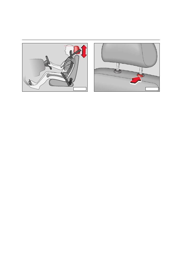
The head restraints are height adjustable
and  should  be  set to  suit the  size  of the
occupant. 

Correctly

adjusted 

head

restraints together  with  the  seat belts
offer  effective  protection.  The  front head
restraints can also be adjusted to a differ-
ent angle.

A

Ad

djju

us

sttiin

ng

g h

he

eiig

gh

htt

• 

Grip  sides of head  restraint with  both

hands and pull up or push down.

• 

The  best protection  is obtained  when

the  upper  edge  of restraint is a

att  lle

ea

as

stt at

eye level or higher.

R

Re

em

mo

ov

viin

ng

g a

an

nd

d iin

ns

stta

alllliin

ng

g

To  remove,  pull restraints up  to  the  stop,
press button (arrow) and at the same time
take restraints out.

To remove the rear head restraint first pull
the backrest forwards a little.

To  install again,  push  the  restraint rods
into  the  guides until they are  heard  to
engage. You do not need to press the key.

B45-016C

B1S-017P

-------------------------------------------------------------------------------------------------------------------------------------------------------------

-------------------------------------------------------------------------------------------------------------------------------------------------------------

SEATS AND LUGGAGE COMPARTMENT 

–––––––––––––––––––––––––––––––––––––––––––––––––––

2.63

HANDLING INSTRUCTIONS

A

Arrm

mrre

es

stt*

*

F

Frro

on

ntt a

arrm

mrre

es

stt*

*

The  armrest can  be  adjusted  to  several
different positions.

To  adjust,  press the  button  in  the  front
end  of the  armrest A

A and  fold  down  the

rest.  Then  raise  the  rest notch  by notch
until the  desired  position  has been
reached.

There  is a  stowage  compartment in  the
armrest. To open, press button B

B.

When  the  armrest is folded  down,  free-
dom  of movement.  For  this reason,  the
armrest should not be folded down when
driving in town traffic

B45-022C

-------------------------------------------------------------------------------------------------------------------------------------------------------------

-------------------------------------------------------------------------------------------------------------------------------------------------------------

2.64

–––––––––––––––––––––––––––––––––––––––––––––––––––

SEATS AND LUGGAGE COMPARTMENT

HANDLING INSTRUCTIONS

6

6 –

– S

Se

ea

att h

he

ea

attiin

ng

g*

* ffo

orr lle

efftt s

se

ea

att

The  cushion  and  backrest of the  front
seats can be heated electrically when the
ignition is on.

The heating is switched on and regulated
to your comfort with the knurled wheel.

To  switch  heating  off,  turn  knurled  wheel
to the basic position (

0).

7

7 –

– S

Se

ea

att h

he

ea

attiin

ng

g*

* ffo

orr rriig

gh

htt s

se

ea

att

The  cushion  and  backrest of the  front
seats can be heated electrically when the
ignition is on.

The heating is switched on and regulated
to your comfort with the knurled wheel.

To  switch  heating  off,  turn  knurled  wheel
to the basic position (

0).

The  steering  column  can  be  adjusted  at
will both  for  reach  and  for  height.  Press
the  lever  A

A beneath  the  steering  column

down and move the steering wheel to the
desired  position.  Then  press the  lever
firmly up again.

W

Wa

arrn

niin

ng

g

T

Th

he

e  s

stte

ee

erriin

ng

g  c

co

ollu

um

mn

n  m

ma

ay

y  o

on

nlly

y

b

be

e  a

ad

djju

us

stte

ed

d  w

wh

hiills

stt  tth

he

e  v

ve

eh

hiic

clle

e  iis

s

s

stta

attiio

on

na

arry

y..

F

Fo

orr  s

sa

affe

etty

y  rre

ea

as

so

on

ns

s,,  tth

he

e  lle

ev

ve

err

m

mu

us

stt a

allw

wa

ay

ys

s b

be

e ffiirrm

mlly

y p

prre

es

ss

se

ed

d u

up

p,,

s

so

o tth

ha

att tth

he

e p

po

os

siittiio

on

n o

off tth

he

e s

stte

ee

erriin

ng

g

c

co

ollu

um

mn

n d

do

oe

es

s n

no

ott s

su

ud

dd

de

en

nlly

y c

ch

ha

an

ng

ge

e

w

wh

hiille

e tth

he

e v

ve

eh

hiic

clle

e iis

s iin

n m

mo

ottiio

on

n..

H

He

ea

atte

ed

d s

se

ea

atts

s*

*

A

Ad

djju

us

stta

ab

blle

e s

stte

ee

erriin

ng

g c

co

ollu

um

mn

n*

*

BAL

FAD

R.D.S

E-O-N

LOUD

MONO

TAPE

CD

CHANGER
CONTROL

FM
AM

RDS

TP
AS

SCAN

CD

AURA

1

2

3

SCAN

TRACK

SOUND SYSTEM

Cr

6

7

TO8-018

A

TO8-018A

-------------------------------------------------------------------------------------------------------------------------------------------------------------

-------------------------------------------------------------------------------------------------------------------------------------------------------------

SEATS AND LUGGAGE COMPARTMENT

––––––––––––––––––––––––––––––––––––––––––––––––––––

2.65

HANDLING INSTRUCTIONS

T

Th

he

e m

mo

ov

ve

em

me

en

ntt o

off tth

he

e p

pe

ed

da

alls

s m

mu

us

stt n

no

ott

b

be

e rre

es

sttrriic

ctte

ed

d!!

F

Fo

orr  tth

hiis

s  rre

ea

as

so

on

n,,  d

do

o  n

no

ott  llo

oc

ca

atte

e  a

an

ny

y

iitte

em

ms

s iin

n tth

he

e ffo

oo

ottw

we

ellll w

wh

hiic

ch

h c

co

ou

ulld

d rro

ollll

o

orr s

slliid

de

e u

un

nd

de

errn

ne

ea

atth

h tth

he

e p

pe

ed

da

alls

s..

Around  the  pedal area  there  should  not
be any foot mats or other additional floor
covering materials:

• 

In the case of defects in the brake sys-

tem, a greater pedal travel may be neces-
sary.

• 

It should always be possible to depress

the clutch and accelerator pedals fully.

• 

All pedals must be  able  to  return,

unhindered, to their rest positions.

For  these  reasons,  the  only foot mats
which may be used are those which leave
the pedal area completely free and which
are prevented from slipping.

W

Wa

arrn

niin

ng

g

U

Un

nd

de

err  n

no

o  c

ciirrc

cu

um

ms

stta

an

nc

ce

es

s  s

sh

ho

ou

ulld

d

a

an

ny

y  iitte

em

ms

s  b

be

e  k

ke

ep

ptt  iin

n  tth

he

e  ffo

oo

ottw

we

ellll,,

a

as

s  tth

he

ey

y  c

co

ou

ulld

d  b

bllo

oc

ck

k  tth

he

e  p

pe

ed

da

alls

s  iin

n

c

ca

as

se

e o

off a

a s

su

ud

dd

de

en

n b

brra

ak

kiin

ng

g m

ma

an

no

oe

eu

u--

v

vrre

e..

Y

Yo

ou

u  w

wo

ou

ulld

d  n

no

o  llo

on

ng

ge

err  b

be

e  a

ab

blle

e  tto

o

b

brra

ak

ke

e,, c

ch

ha

an

ng

ge

e g

ge

ea

arr o

orr a

ac

cc

ce

elle

erra

atte

e!!

In  the  interests of good  handling  ensure
that the  load  (persons and  luggage)  is
distributed  evenly.  Heavy items should
always be carried as near to the rear axle
as possible  or  better  still,  between  the
axles.

Stale  air  escapes through  ventilation
openings in the side trim* of the luggage
compartment. For this reason, it is best to
keep these openings uncovered.

P

Pe

ed

da

alls

s

L

Lu

ug

gg

ga

ag

ge

e c

co

om

mp

pa

arrttm

me

en

ntt

-------------------------------------------------------------------------------------------------------------------------------------------------------------

-------------------------------------------------------------------------------------------------------------------------------------------------------------

2.66

–––––––––––––––––––––––––––––––––––––––––––––––––––

SEATS AND LUGGAGE COMPARTMENT

HANDLING INSTRUCTIONS

W

Wa

arrn

niin

ng

g n

no

otte

es

s

W

Wa

arrn

niin

ng

g

T

Th

he

e  p

pe

errm

miis

ss

siib

blle

e  p

pa

ay

yllo

oa

ad

ds

s  a

an

nd

d

G

GV

VW

W  m

mu

us

stt  n

no

ott  b

be

e  e

ex

xc

ce

ee

ed

de

ed

d  –

–  s

se

ee

e

c

ch

ha

ap

ptte

err "

"T

Te

ec

ch

hn

niic

ca

all D

Da

atta

a"

"..

IItt  s

sh

ho

ou

ulld

d  b

be

e  n

no

otte

ed

d  tth

ha

att  w

wh

he

en

n

ttrra

an

ns

sp

po

orrttiin

ng

g  h

he

ea

av

vy

y  iitte

em

ms

s  tth

he

e  h

ha

an

n--

d

dlliin

ng

g  w

wiillll  c

ch

ha

an

ng

ge

e  d

du

ue

e  tto

o  tth

he

e  d

diis

s--

p

plla

ac

ce

em

me

en

ntt o

off tth

he

e c

ce

en

nttrre

e o

off g

grra

av

viitty

y..

D

Drriiv

viin

ng

g  s

stty

ylle

e  a

an

nd

d  s

sp

pe

ee

ed

d  m

mu

us

stt,,

tth

he

erre

effo

orre

e,, b

be

e a

alltte

erre

ed

d tto

o s

su

uiitt..

T

Th

he

e llo

oa

ad

d m

mu

us

stt b

be

e s

stto

ow

we

ed

d iin

n s

su

uc

ch

h

a

a w

wa

ay

y tth

ha

att n

no

o iitte

em

ms

s c

ca

an

n fflly

y ffo

orrw

wa

arrd

d

iiff tth

he

e b

brra

ak

ke

es

s a

arre

e a

ap

pp

plliie

ed

d s

su

ud

dd

de

en

nlly

y

–  u

us

se

e  tth

he

e  lla

as

sh

hiin

ng

g  e

ey

ye

es

s*

*  iiff  n

ne

ec

ce

es

s--

s

sa

arry

y..

N

No

o  p

pe

eo

op

plle

e  o

orr  c

ch

hiilld

drre

en

n  a

arre

e  tto

o

ttrra

av

ve

ell  iin

n  tth

he

e  llo

oa

ad

diin

ng

g  a

arre

ea

a  o

orr  tth

he

e

b

bo

oo

ott..  A

Allll  p

pa

as

ss

se

en

ng

ge

errs

s  m

mu

us

stt  w

we

ea

arr

s

se

ea

att  b

be

elltts

s..  S

Se

ee

e  "

"S

Se

ea

att  b

be

elltts

s"

"  c

ch

ha

ap

p--

tte

err..

N

Ne

ev

ve

err  d

drriiv

ve

e  w

wiitth

h  tth

he

e  b

bo

oo

ott

lliid

d/

/tta

aiillg

ga

atte

e  o

op

pe

en

n  o

orr  n

no

ott  p

prro

op

pe

errlly

y

c

cllo

os

se

ed

d.. E

Ex

xh

ha

au

us

stt g

ga

as

s c

co

ou

ulld

d tth

he

en

n b

be

e

d

drra

aw

wn

n iin

ntto

o tth

he

e v

ve

eh

hiic

clle

e iin

ntte

erriio

orr..

L

La

as

sh

hiin

ng

g e

ey

ye

es

s*

*

On  the  saloon,  four  eyelets are  provided
in  the  luggage  compartment for  securing
items of luggage. There are two eyelets in
the  front sides of the  luggage  compart-
ment,  one  left and  one  right.  The  other
two  eyelets are  near  the  loading  edge
(see illustration). 

The  lashing  eyes comply with  Standard
DIN 75410.

LEO-020

-------------------------------------------------------------------------------------------------------------------------------------------------------------

-------------------------------------------------------------------------------------------------------------------------------------------------------------

SEATS AND LUGGAGE COMPARTMENT 

–––––––––––––––––––––––––––––––––––––––––––––––––––

2.67

HANDLING INSTRUCTIONS

R

Re

ea

arr s

sh

he

ellff

R

Re

em

mo

ov

viin

ng

g tth

he

e s

sh

he

ellff

From the rear end of the car, with the tail-
gate raised, unhitch the stays B

B from their

housings A

A.  Remove  the  shelf from  its

housing, pulling outwards.

The rear shelf can be used to place cloth-
ing  but care  should  be  taken  to  avoid
reducing  visibility through  the  rear  win-
dow.

To  ensure  correct ventilation  of the  car
interior,  the  slot between  the  shelf and
the rear window must not be obstructed. 

W

Wa

arrn

niin

ng

g

N

No

o  h

he

ea

av

vy

y  o

orr  h

ha

arrd

d  o

ob

bjje

ec

ctts

s  m

mu

us

stt  b

be

e

s

stto

orre

ed

d  o

on

n  tth

he

e  s

sh

he

ellff  s

siin

nc

ce

e  tth

hiis

s

c

co

ou

ulld

d  e

en

nd

da

an

ng

ge

err  tth

he

e  s

sa

affe

etty

y  o

off  tth

he

e

o

oc

cc

cu

up

pa

an

ntts

s  o

off  tth

he

e  v

ve

eh

hiic

clle

e  iin

n  tth

he

e

c

ca

as

se

e o

off s

su

ud

dd

de

en

n b

brra

ak

kiin

ng

g..

T

Th

he

e s

stto

orra

ag

ge

e o

off s

su

uc

ch

h h

he

ea

av

vy

y o

orr h

ha

arrd

d

o

ob

bjje

ec

ctts

s  o

on

n  tth

he

e  rre

ea

arr  s

sh

he

ellff  c

co

ou

ulld

d

rre

es

su

ulltt iin

n d

da

am

ma

ag

ge

e tto

o tth

he

e h

he

ea

atte

err e

elle

e--

m

me

en

ntts

s iin

n tth

he

e rre

ea

arr w

wiin

nd

do

ow

w..

A

B

IB9-019

-------------------------------------------------------------------------------------------------------------------------------------------------------------

-------------------------------------------------------------------------------------------------------------------------------------------------------------

2.68

–––––––––––––––––––––––––––––––––––––––––––––––––––

SEATS AND LUGGAGE COMPARTMENT

HANDLING INSTRUCTIONS

IIn

nc

crre

ea

as

siin

ng

g b

bo

oo

ott s

sp

pa

ac

ce

e*

*

You  may tip  the  rear  seats forwards to
increase the boot space: if it is a split seat
each half can be tipped separately.

Headrests must be removed before lower-
ing the back seat*. To do so you will need
to push the back of the seat forward a lit-
tle. See the "Headrests" chapter.

Place  the  safety belts through  the
tongues in  the  housing  provided  for  this
purpose.

The front seats must be placed so that the
back seats do  not collide  with  them,  to
avoid damage.

F

Fo

olld

diin

ng

g d

do

ow

wn

n tth

he

e s

se

ea

att

• 

Pull on  the  tape  (arrow  1

1)  to  raise  the

cushion  a  little  and  then  pull it forwards
as far as possible. Then raise the rear part
of the cushion (arrow 2

2).

R

Re

ea

arr s

se

ea

att

1

2

B1J-007D

TO2-003

-------------------------------------------------------------------------------------------------------------------------------------------------------------

-------------------------------------------------------------------------------------------------------------------------------------------------------------

SEATS AND LUGGAGE COMPARTMENT 

–––––––––––––––––––––––––––––––––––––––––––––––––––

2.69

HANDLING INSTRUCTIONS

• 

Pull the release lever on the backrest in

the  direction  of the  arrow  (or  both  levers
at the  same  time  if the  seat is not split)
and lower the backrest.

R

Ra

aiis

siin

ng

g tth

he

e s

se

ea

att

• 

First lift up the backrest.

• 

Lift the cushion and then push it back-

wards until it fits into place. When you do,
p

pu

ullll  tth

he

e  m

miid

dd

dlle

e  s

se

ea

att  b

be

elltt  o

ou

utt,,  o

otth

he

err--

w

wiis

se

e  iitt  w

wiillll  b

be

e  ttrra

ap

pp

pe

ed

d  b

be

ettw

we

ee

en

n  tth

he

e

s

se

ea

att a

an

nd

d tth

he

e b

ba

ac

ck

krre

es

stt a

an

nd

d y

yo

ou

u w

wiillll n

no

ott

b

be

e a

ab

blle

e tto

o u

us

se

e iitt..

A

Alls

so

o m

ma

ak

ke

e s

su

urre

e tth

he

e s

siid

de

e b

be

elltts

s a

arre

e n

no

ott

ttrra

ap

pp

pe

ed

d b

by

y tth

he

e b

ba

ac

ck

krre

es

stt..

W

Wa

arrn

niin

ng

g

T

Th

he

e  rre

ea

arr  s

se

ea

att  b

ba

ac

ck

krre

es

stt  m

mu

us

stt  b

be

e

p

prro

op

pe

errlly

y  e

en

ng

ga

ag

ge

ed

d  s

so

o  tth

ha

att  a

arrttiic

clle

es

s

iin

n  tth

he

e  llu

ug

gg

ga

ag

ge

e  a

arre

ea

a  d

do

o  n

no

ott  s

slliid

de

e

ffo

orrw

wa

arrd

d  iiff  tth

he

e  b

brra

ak

ke

es

s  a

arre

e  a

ap

pp

plliie

ed

d

s

su

ud

dd

de

en

nlly

y..

B1J-008D

B1J-004D

-------------------------------------------------------------------------------------------------------------------------------------------------------------

-------------------------------------------------------------------------------------------------------------------------------------------------------------

2.70

–––––––––––––––––––––––––––––––––––––––––––––––––––

SEATS AND LUGGAGE COMPARTMENT

HANDLING INSTRUCTIONS

When loads are to be carried on the roof,
the following should be noted:

• 

As the rain channels are moulded into

the roof for streamlining reasons, the nor-
mal type  of roof rack cannot be  used.  To
avoid  risks we  advise  that only the  cross
bars provided by the factory are used.

• 

These  cross bars are  the  basis for  a

complete  roof load  carrying  system.  For
safety reasons when  carrying  luggage,
bicycles, surf boards, skis and boats, the
appropriate 

special

adapters

are

required.

The roof rack system must be installed

according  to  the  enclosed  instructions.
Open the plastic covers to secure the feet
of the rack to the roof.

When fitting the feet to the roof make sure
they fit exactly into  the  special grooves
and  properly attach  to  the  appropriate
part of the groove.

• 

Distribute  the  load  evenly.  Each  cross

bar  may carry 40  kg  if loaded  uniformly
over  the  full length.  The  permissible  roof
load  (including  the  carrier  system)  of 75
kg  and  the  permissible  gross vehicle
weight must not be  exceeded.  See  chap-
ter "Technical Data".

W

Wa

arrn

niin

ng

g

W

Wh

he

en

n  c

ca

arrrry

yiin

ng

g  h

he

ea

av

vy

y  o

orr  lla

arrg

ge

e

o

ob

bjje

ec

ctts

s  o

on

n  tth

he

e  rro

oo

off,,  b

be

ea

arr  iin

n  m

miin

nd

d

tth

ha

att tth

he

e v

ve

eh

hiic

clle

e h

ha

an

nd

dlliin

ng

g c

ch

ha

an

ng

ge

es

s

d

du

ue

e  tto

o  tth

he

e  d

diis

sp

plla

ac

ce

em

me

en

ntt  o

off  tth

he

e

c

ce

en

nttrre

e o

off g

grra

av

viitty

y a

an

nd

d tth

he

e iin

nc

crre

ea

as

se

ed

d

a

arre

ea

a e

ex

xp

po

os

se

ed

d tto

o tth

he

e w

wiin

nd

d.. 

D

Drriiv

viin

ng

g  s

stty

ylle

e  a

an

nd

d  s

sp

pe

ee

ed

d  m

mu

us

stt  b

be

e

a

ad

da

ap

ptte

ed

d tto

o a

allllo

ow

w ffo

orr tth

hiis

s..

• 

If your vehicle has a sliding/lifting sun

roof make sure it does not collide with the
load.

R

Ro

oo

off rra

ac

ck

k*

*

-------------------------------------------------------------------------------------------------------------------------------------------------------------

-------------------------------------------------------------------------------------------------------------------------------------------------------------

SEATS AND LUGGAGE COMPARTMENT 

–––––––––––––––––––––––––––––––––––––––––––––––––––

2.71

HANDLING INSTRUCTIONS

Press forcefully on  the  cover  on  the
marked side in the direction of the arrow.
Lift the  aforementioned  cover  until there
is a 90° angle in relation to the roof of the
vehicle.

Then place the roof rack* in the mounting
for  roof racks (note  instructions included
in the roof rack*).

To  close  proceed  in  reverse.  Ensure  that
the  cover  is well closed.  It must be  flush
to the roof channels.

90°

90°

LEO-045

-------------------------------------------------------------------------------------------------------------------------------------------------------------

-------------------------------------------------------------------------------------------------------------------------------------------------------------

2.72

–––––––––––––––––––––––––––––––––––––––––––––––––––

SEATS AND LUGGAGE COMPARTMENT

HANDLING INSTRUCTIONS

F

Frro

on

ntt a

as

sh

httrra

ay

y

O

Op

pe

en

niin

ng

g

Push the front of the ashtray B

B. See figure.

E

Em

mp

ptty

yiin

ng

g

Take  the  ashtray by the  side  groves (A

A)

pulling it upwards.

R

Re

ep

plla

ac

ciin

ng

g

Push in.

C

Cllo

os

siin

ng

g

It can  only be  closed  by pressing  on  the
llo

ow

we

err p

pa

arrtt o

off tth

he

e a

as

sh

httrra

ay

y (C

C)..

R

Re

ea

arr

O

Op

pe

en

niin

ng

g

Open the lid.

E

Em

mp

ptty

yiin

ng

g

Remove  the  inside  by pulling  it upwards,
with the lid open.

R

Re

ep

plla

ac

ciin

ng

g

Push in and downwards.

A

As

sh

httrra

ay

ys

s

B8L-067

B

C

A

B8L-098

-------------------------------------------------------------------------------------------------------------------------------------------------------------

-------------------------------------------------------------------------------------------------------------------------------------------------------------

SEATS AND LUGGAGE COMPARTMENT 

–––––––––––––––––––––––––––––––––––––––––––––––––––

2.73

HANDLING INSTRUCTIONS

The  cigarette  lighter  is switched  on  by
pushing in the element. When the heating
element glows,  the  lighter  springs out
automatically –  pull it out immediately
and use it.

W

Wa

arrn

niin

ng

g

E

Ex

xc

ce

errc

ciis

se

e  c

ca

au

uttiio

on

n  w

wh

he

en

n  u

us

siin

ng

g  tth

he

e

c

ciig

ga

arre

etttte

e  lliig

gh

htte

err..  IItt  c

ca

an

n  c

ca

au

us

se

e

b

bu

urrn

ns

s..

T

Th

he

e  c

ciig

ga

arre

etttte

e  lliig

gh

htte

err  a

an

nd

d  tth

he

e

s

so

oc

ck

ke

ett a

alls

so

o w

wo

orrk

k w

wh

he

en

n tth

he

e iig

gn

niittiio

on

n

iis

s  s

sw

wiittc

ch

he

ed

d  o

offff  a

an

nd

d  tth

he

e  k

ke

ey

y

rre

em

mo

ov

ve

ed

d..

F

Fo

orr  tth

hiis

s  rre

ea

as

so

on

n  c

ch

hiilld

drre

en

n  s

sh

ho

ou

ulld

d

n

ne

ev

ve

err b

be

e lle

efftt iin

n tth

he

e v

ve

eh

hiic

clle

e o

on

n tth

he

eiirr

o

ow

wn

n..

The  1

12

2--V

Vo

olltt  s

so

oc

ck

ke

ett of the  lighter  can  be

used  for  other  electrical accessories with
a  capacity of up  to  120  Watts.  When  the
engine  is not running  this will however
discharge the battery. For further informa-
tion see “Accessories”.

E

Elle

ec

cttrriic

c s

so

oc

ck

ke

ett iin

n tth

he

e b

bo

oo

ott*

*

The electric socket is located in the wheel
area on the left side.

It can  be  used  for  electrical accessories
with a maximum capacity of 150 W. When
the engine is not running, however, it will
discharge the battery. For further informa-
tion see the chapter on “Accessories”.

W

Wa

arrn

niin

ng

g

F

Fo

orr  s

sa

affe

etty

y  rre

ea

as

so

on

ns

s  tth

he

e  g

gllo

ov

ve

e  c

co

om

m--

p

pa

arrttm

me

en

ntt  lliid

d  s

sh

ho

ou

ulld

d  a

allw

wa

ay

ys

s  b

be

e

c

cllo

os

se

ed

d w

wh

hiille

e d

drriiv

viin

ng

g..

Lift the catch in order to open the passen-
ger side glove compartment*.

S

Stto

ow

wa

ag

ge

e b

bo

ox

x w

wiitth

h C

CD

D--C

Ch

ha

an

ng

ge

err*

*

Depending  on  which  car  radio  they are
equipped with, some vehicles have a CD-
Changer* for up to 6 compact disks in the
stowage box.

C

Ciig

ga

arre

etttte

e lliig

gh

htte

err/

/

e

elle

ec

cttrriic

c s

so

oc

ck

ke

ett

S

Stto

ow

wa

ag

ge

e b

bo

ox

x

TO8-020

-------------------------------------------------------------------------------------------------------------------------------------------------------------

-------------------------------------------------------------------------------------------------------------------------------------------------------------

2.74

–––––––––––––––––––––––––––––––––––––––––––––––––––

SEATS AND LUGGAGE COMPARTMENT

HANDLING INSTRUCTIONS

V

Ve

eh

hiic

clle

e w

wa

alllle

ett s

stto

ow

wa

ag

ge

e

c

co

om

mp

pa

arrttm

me

en

ntt

This stowage box is intended for the vehi-
cle wallet.

N

No

otte

e

If the  vehicle  wallet does not fit in  this
compartment you may store it in the glove
compartment on the passenger side or in
any of the stowage boxes on the doors.

Located in the central console.

O

Op

pe

en

niin

ng

g

Press the edge of the drink can holder and
it will spring open.

C

Cllo

os

siin

ng

g

Push the drink can holder closed.

W

Wa

arrn

niin

ng

g

T

Th

he

e  d

drriin

nk

k  c

ca

an

n  h

ho

olld

de

err  s

sh

ho

ou

ulld

d

a

allw

wa

ay

ys

s  rre

em

ma

aiin

n  c

cllo

os

se

ed

d  w

wh

hiille

e  d

drrii--

v

viin

ng

g  tto

o  rre

ed

du

uc

ce

e  rriis

sk

k  iin

n  tth

he

e  e

ev

ve

en

ntt  o

off

s

su

ud

dd

de

en

n b

brra

ak

kiin

ng

g o

orr a

an

n a

ac

cc

ciid

de

en

ntt..

D

Drriin

nk

k c

ca

an

n h

ho

olld

de

err*

*

LEO-022

-------------------------------------------------------------------------------------------------------------------------------------------------------------

-------------------------------------------------------------------------------------------------------------------------------------------------------------

CLIMATE CONTROL 

––––––––––––––––––––––––––––––––––––––––––––––––––––––––––––––––––––––

2.75

HANDLING INSTRUCTIONS

W

Wa

arrn

niin

ng

g

F

Fo

orr  rro

oa

ad

d  s

sa

affe

etty

y  iitt  iis

s  iim

mp

po

orrtta

an

ntt

tth

ha

att  a

allll  w

wiin

nd

do

ow

ws

s  a

arre

e  ffrre

ee

e  o

off  iic

ce

e,,

s

sn

no

ow

w  a

an

nd

d  m

miis

stt..  O

On

nlly

y  tth

he

en

n  c

ca

an

n

c

clle

ea

arr v

viis

siio

on

n b

be

e g

gu

ua

arra

an

ntte

ee

ed

d..

Y

Yo

ou

u  s

sh

ho

ou

ulld

d  tth

he

erre

effo

orre

e  ffa

am

miilliia

arriis

se

e

y

yo

ou

urrs

se

ellff w

wiitth

h tth

he

e c

co

orrrre

ec

ctt o

op

pe

erra

attiio

on

n

o

off tth

he

e h

he

ea

attiin

ng

g a

an

nd

d v

ve

en

nttiilla

attiio

on

n s

sy

ys

s--

tte

em

m  a

as

s  w

we

ellll  a

as

s  rre

em

mo

ov

viin

ng

g  d

da

am

mp

p--

n

ne

es

ss

s a

an

nd

d ffrro

os

stt ffrro

om

m tth

he

e w

wiin

nd

do

ow

ws

s..

T

Th

he

e  h

hiig

gh

he

es

stt  p

po

os

ss

siib

blle

e  lle

ev

ve

ell  o

off

h

he

ea

attiin

ng

g  a

an

nd

d  q

qu

uiic

ck

k  d

de

effrro

os

sttiin

ng

g  o

off

tth

he

e w

wiin

nd

do

ow

ws

s c

ca

an

n o

on

nlly

y b

be

e a

ac

ch

hiie

ev

ve

ed

d

w

wh

he

en

n  tth

he

e  e

en

ng

giin

ne

e  h

ha

as

s  a

ac

ch

hiie

ev

ve

ed

d  iitts

s

o

op

pe

erra

attiin

ng

g tte

em

mp

pe

erra

attu

urre

e..

V

Ve

en

ntts

s

The illustration shows the air vents on the
dashboard.

Cooled, heated or unheated air comes out
of all the vents.

All vents can  be  adjusted  by swivelling
control C

C (see illustration on next page).

Vents 3

3 and 4

4 open and close separately,

with knurled wheels at the side.

The  air  flow  from  the  vents can  be
adjusted horizontally or vertically.

H

He

ea

attiin

ng

g a

an

nd

d v

ve

en

nttiilla

attiio

on

n

5

5

5

5

5

5

3

2

3

2

1

1

1

4

4

LEO-023

-------------------------------------------------------------------------------------------------------------------------------------------------------------

-------------------------------------------------------------------------------------------------------------------------------------------------------------

2.76

––––––––––––––––––––––––––––––––––––––––––––––––––––––––––––––––––––––

CLIMATE CONTROL

HANDLING INSTRUCTIONS

C

Co

on

nttrro

olls

s

A

A –

– T

Te

em

mp

pe

erra

attu

urre

e s

se

elle

ec

ctto

orr

The  temperature  can  be  gradually
increased  by turning  the  control clock-
wise.

B

B –

– B

Bllo

ow

we

err

Air flow can be adjusted to four speeds. 

In position 

0 the fan is switched off.

C

C –

– S

Sw

wiiv

ve

ell k

kn

no

ob

b ffo

orr a

aiirr d

diis

sttrriib

bu

uttiio

on

n

A

Aiirr ffllo

ow

w ffo

orr 

ffo

oo

ott w

we

ellll

Vents 5

5 are opened.

Vents 3

3 and  4

4 must be  closed  for  all the

air to go to the feet.

A

Aiirr ffllo

ow

w ffo

orr tth

he

w

wiin

nd

ds

sc

crre

ee

en

n

In  this position  you  cannot connect posi-
tion D

D for air recirculation.

Additionally, vents 3

3 can be used to direct

hot air to the side windows.

Vents 1

1 and 2

2 are opened.

A

Aiirr ffllo

ow

w ffrro

om

tth

he

e v

ve

en

ntts

s

Vents 1

1, 2

2 and 5

5 are closed. The air comes

out of vents 3

3 and 4

4.

In  the  above  positions there  is always
some air leaking out of the other vents.

D

D –

– A

Aiirr rre

ec

ciirrc

cu

ulla

attiio

on

n

In this mode, no air is drawn from outside
and  air  is drawn  in  from  the  vehicle  inte-
rior and recirculated.

The  air  recirculation  function  stops pol-
luted  air  from  outside  entering  the  vehi-
cle.  Y

Yo

ou

u  s

sh

ho

ou

ulld

d  n

no

ott  d

drriiv

ve

e  ffo

orr  tto

oo

o  llo

on

ng

g

w

wiitth

h tth

hiis

s m

mo

od

de

e s

sw

wiittc

ch

he

ed

d o

on

n..

IIff  tth

he

e  w

wiin

nd

do

ow

ws

s  s

stte

ea

am

m  u

up

p  y

yo

ou

u  s

sh

ho

ou

ulld

d

p

prre

es

ss

s tth

he

e a

aiirr c

ciirrc

cu

ulla

attiio

on

n b

bu

utttto

on

n a

ag

ga

aiin

n

iim

mm

me

ed

diia

atte

elly

y  tto

o  s

sw

wiittc

ch

h  iitt  o

offff  o

orr  s

se

elle

ec

ctt

tth

he

e p

po

os

siittiio

on

..

BAL

FAD

TREB

BASS

R.D.S

E-O-N

LOUD

MONO

TAPE

CD

PTY

PROG

CHANGER
CONTROL

PHONES

FM
AM

RDS

TP
AS

TRACK  –

<

TRACK  +

>

DX

MAN

SCAN

CD

RND

AUR

4

5

6

1

2

3

SCAN

RND

TRACK

A

B

C

D

TO2-001

-------------------------------------------------------------------------------------------------------------------------------------------------------------

-------------------------------------------------------------------------------------------------------------------------------------------------------------

CLIMATE CONTROL 

––––––––––––––––––––––––––––––––––––––––––––––––––––––––––––––––––––––

2.77

HANDLING INSTRUCTIONS

A

Ad

djju

us

sttm

me

en

ntt iin

ns

sttrru

uc

cttiio

on

ns

s

D

De

effrro

os

sttiin

ng

g w

wiin

nd

ds

sc

crre

ee

en

n a

an

nd

d s

siid

de

e

w

wiin

nd

do

ow

ws

s

• 

Rotary switch B

B to stage IIIIII.

• 

Rotary regulator A

A turned fully to right.

• 

Rotary regulator C

C to ....................

• 

Adjust vents 3

3 so that additional warm

air can be directed to the side windows.

D

De

em

miis

sttiin

ng

g w

wiin

nd

ds

sc

crre

ee

en

n a

an

nd

d s

siid

de

e

w

wiin

nd

do

ow

ws

s

When the windows mist up due to high air
humidity,  e.g.  when  it is raining,  we  rec-
ommend the following settings:

• 

Rotary switch B

B to stage IIII or IIIIII.

• 

Rotary regulator  A

A,  if necessary,  into

heating range.

• 

Rotary regulator  C

C as required,  between

and

.

• 

Additional warm air can be directed to

the side windows via vents 3

3.

H

He

ea

attiin

ng

g iin

ntte

erriio

orr q

qu

uiic

ck

klly

y

• 

Rotary switch B

B to level IIIIII.

• 

Rotary regulator C

C to ....................

• 

Turn control A

A as far clockwise as pos-

sible.

• 

Open vents 3

3.

H

He

ea

attiin

ng

g iin

ntte

erriio

orr c

co

om

mffo

orrtta

ab

blly

y

When  the  windows are  clear  and  the
desired temperature has been reached we
recommend the following settings:

• 

Rotary switch B

B to level IIII or IIIIII.

• 

Rotary regulator  A

A at the  desired  heat

output.

• 

Rotary regulator C

C to  ...................

• 

Set vents 3

3.

V

Ve

en

nttiilla

attiio

on

n ((ffrre

es

sh

h a

aiirr o

op

pe

erra

attiio

on

n))

With  the  following  settings,  unheated
fresh air flows from vents 3

3 and 4

4:

• 

Rotary switch  B

B to desired stage (level

IIIIIIII for maximum air flow).

• 

Rotary regulator  A

A anti–clockwise  to

the stop

• 

Rotary regulator C

C to ....................

• 

Vents 3

3 and 4

4 open.

If required,  regulator  C

C can  be  turned  to

another position.

-------------------------------------------------------------------------------------------------------------------------------------------------------------


Content      ..     5      6      7      8     ..