Seat Ateca. Service Manual - part 10


  Index      Seat     Seat Ateca. Service Manual


Search            copyright infringement  


Content      ..     8      9      10      11     ..


Seat Ateca. Service Manual - part 10


-------------------------------------------------------------------------------------------------------------------------------------------------------------
Seats and head restraints

Do not sit on the seat with clothing that is

wet or damp.

Do not leave clothing that is wet or damp

on the seat.

Do not spill liquid on the seat.

CAUTION

To avoid damaging the heating elements of

the seat heaters, please do not kneel on the
seat or apply sharp pressure to a single point
on the seat cushion or backrest.

Liquids, sharps objects and insulating ma-

terials (e.g. covers or child seats) can damage
the seat heating.

In the event of smells, switch off the seat

heating immediately and have it inspected by
a specialised workshop.

For the sake of the environment

The seat heating should remain on only when
needed. Otherwise, it is an unnecessary fuel
waste.

Front centre armrest

The centre armrest can be adjusted to various
levels.

Adjusting the centre armrest

To adjust the tilt, lift the armrest from the
starting position so that it is engaged.

To return the armrest to the starting posi-
tion, remove the armrest from the upper
fixed position and lower it.

The armrest can be moved backwards and
forwards.

Folding down and lifting the rear seat
backrest

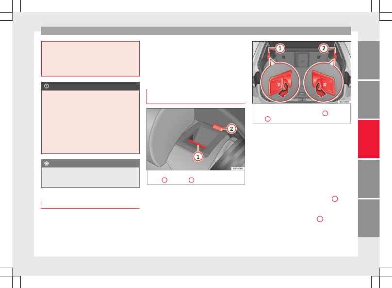
Fig. 145 

On the rear seat backrest: release

catch 

1

; red mark 

2

.

Fig. 146 

In the luggage compartment: levers

for remote release of the left part 

1

 and right

part 

2

 of the rear seat backrest.

The rear seat backrest is split and each part
be lowered separately to extend the luggage
compartment.

When the rear seat backrest is lowered no-
body else can travel in the corresponding
seats (not even a child).

Lowering the rear seat backrest with the un-
lock button

Lower the head restraint properly.

Push the unlock button 

››› 

Fig. 145


1

 for-

wards and at the same time lift the backrest.

The rear seat backrest is not engaged when

the red marking of the button 

2

 is visible.

Lowering the rear seat backrest with the re-
mote release lever

Lower the head restraint properly.

»

149

Tec

hnic

al

 d

at

a

Adv

ic

e

Oper

ation

Emer

genc

ie

s

Saf

ety

-------------------------------------------------------------------------------------------------------------------------------------------------------------

-------------------------------------------------------------------------------------------------------------------------------------------------------------

Operation

Open the rear lid.

Pull the remote release lever of the left part

››› 

Fig. 146


1

 or right part 

2

 of the backrest

in the direction of the arrow. The released
part of the rear seat backrest is folded auto-
matically down and forwards.

If this occurs, close the rear lid.

The rear seat backrest is not engaged when
the red marking of the button 

››› 

Fig. 145


2

is visible.

Folding up the rear seat backrest

Lift the backrest and press it firmly into the

lock until it engages 

››› 

.

It should not be possible to see the red

mark of the unlock button 

2

.

The backrest must be properly engaged.

WARNING

Serious injuries can be caused if the rear seat
backrest is lowered or lifted without due care
and attention.

Never lower or lift the rear seat backrest

while driving.

Do no trap or damage the seat belt when

raising the rear seat backrest.

When lowering or lifting the rear seat back-

rest, keep your hands, fingers, feet and other
body parts out of its path.

For the rear seat belts to offer the necessa-

ry protection all the parts of the rear backrest

must be properly engaged. This is particular-
ly important in the case of the centre rear
seat. If someone is seated in a seat whose
backrest is not properly engaged they will fly
forward, along with the backrest, during an
accident or a sudden driving or braking ma-
noeuvre.

A red signal on the button 

2

 warns that

the backrest is not engaged. Always check
that the red marking is not visible when the
backrest is in the upright position.

When the rear seat backrest is lowered or is

not properly engaged nobody else can travel
in the corresponding seats (not even a child).

CAUTION

Serious damage can be caused to the vehicle
and other objects if the rear seat backrest is
lowered or lifted without due care and atten-
tion.

Before lowering the rear seat backrest, al-

ways adjust the front seats so that neither
the head restraints nor the cushions of the
rear backrest can hit them.

Transport and practical
equipment

Storage compartments

Storage areas under the front seats*

Fig. 147 

Storage compartment under the

front seats.

There is a storage compartment with a cover
under each front seat.

The drawer* is opened by pulling on the han-
dle of the cover 

››› 

Fig. 147

.

To close the drawer, press the cover until it
locks into position.

WARNING

The drawers will hold a maximum weight of

1.5 kg.

150

-------------------------------------------------------------------------------------------------------------------------------------------------------------

-------------------------------------------------------------------------------------------------------------------------------------------------------------

Transport and practical equipment

Do not drive with the drawer cover open.

There is an injury risk for passengers if the
cargo is released in case of sudden braking or
an accident.

Drink holders

Fig. 148 

Centre console: front drink holders.

Front drink holders

Place drinks in the holder 

››› 

Fig. 148

.

Placement of two drinks is possible. There
is also the possibility of placing larger plas-
tic bottles in the trims of the doors.

WARNING

Do not place any hot drinks in the drink

holder while the vehicle is moving. Hot drinks
could spill and cause burns, which may cause
an accident.

Do not use hard china cups or glasses.

These could cause injury in the event of an
accident.

CAUTION

You should avoid putting open drinks con-
tainers in the drink holders. The drinks could
otherwise spill over and cause damage to e.g.
the electrical equipment or the seat covers.

Glove compartment

Fig. 149 

Glove compartment

Opening/closing

To open the glove compartment, pull the
handle in the direction of the arrow.

To close the glove compartment, move the
cover upwards until it engages.

Depending on the vehicle equipment, the CD
player is located in the glove compartment.
Separate operating instructions are enclosed
for this equipment in the corresponding In-
struction Manual.

WARNING

The cover of the glove compartment should
always be closed while driving. Failure to fol-
low this instruction could result in an acci-
dent.

Other storage compartments

You will find more object holders, compart-
ments and supports in other parts of the ve-
hicle:

In the top of the glove compartment in ve-

hicles that do not have a CD reader. The load
of the compartment should not exceed
1.2 kg.

In the centre console under the centre arm-

rest*.

Coat hooks in the door frames 

››› 

.

Other storage compartments are found in

the rear seat, to the left and the right of the
seats.

»

151

Tec

hnic

al

 d

at

a

Adv

ic

e

Oper

ation

Emer

genc

ie

s

Saf

ety

-------------------------------------------------------------------------------------------------------------------------------------------------------------

-------------------------------------------------------------------------------------------------------------------------------------------------------------

Operation

WARNING

Please make sure that any items of clothing

hanging from the coat hooks do not obstruct
your view to the rear.

The coat hooks should only be used for

lightweight clothing. Do not leave any heavy
or sharp objects in the pockets.

Do not use clothes hangers to hang up the

clothing, as this could interfere with the func-
tion of the head-protection airbags.

Socket

Fig. 150 

Centre console: 12 volt socket

Remove the cap located on the centre con-

sole of the socket 

››› 

Fig. 150

.

Insert the plug of the electrical appliance

into the power socket.

Electrical equipment can be connected to the
12 volt power socket. The appliances connec-

ted to each power socket must not exceed a
power rating of 120 Watt.

WARNING

The power socket works only when the igni-
tion is on. Improper use may cause serious
injury or even fire. Children should therefore
not be left in the vehicle unattended if the
button is also left behind. Otherwise there is
a possibility that they may be injured.

CAUTION

Always use the correct type of plugs to avoid
damaging the sockets.

Note

The use of electrical appliances with the en-
gine switched off will cause a battery dis-
charge.

Storing objects

Loading the luggage compartment

All luggage and other loose objects must be
safely secured in the luggage compartment.
Unsecured objects which shift back and forth
could impair the driving safety or driving
characteristics of the vehicle by shifting the
centre of gravity.

Distribute the load evenly in the luggage
compartment.

Place heavy objects as far forward as possi-
ble in the luggage compartment.

Place the heavy objects first.

Secure heavy objects to the fitted fastening
rings 

››› 

page 155

.

WARNING

Loose luggage and other objects in the lug-

gage compartment could cause serious inju-
ries.

Always stow objects in the luggage com-

partment and secure them on the fastening
rings.

Use suitable straps to secure heavy ob-

jects.

During sudden manoeuvres or accidents,

loose objects can be thrown forward, injuring
vehicle occupants or passers-by. This in-
creased risk of injury will be further increased
if a loose object is struck by an inflating air-
bag. If this happens, objects may shoot out-
ward like a missile. Risk of fatal injury.

Please note that the centre of gravity may

shift when transporting heavy objects; this
may affect vehicle handling and lead to an ac-
cident. Therefore, it is essential to adjust
your speed and driving style accordingly, to
avoid accidents.

152

-------------------------------------------------------------------------------------------------------------------------------------------------------------

-------------------------------------------------------------------------------------------------------------------------------------------------------------

Transport and practical equipment

Never exceed the allowed axle weights or

allowed maximum weight. If said weights are
exceeded, the driving characteristics of the
vehicle may change, leading to accidents, in-
juries and damage to the vehicle.

Never leave your vehicle unattended, espe-

cially when the rear lid is open. Children
could climb into the luggage compartment,
closing the door behind them; they will be
trapped and run the risk of death.

Never allow children to play in or around

the vehicle. Close and lock all the doors and
rear lid when you leave the vehicle. Before
you lock the vehicle, make sure that there are
no adults or children in the vehicle.

Note

Air circulation in the vehicle helps reduce

fogging of the windows. Used air escapes
through ventilation slits in the side trim of
the luggage compartment. Ensure that the
ventilation slots are never covered.

Straps for securing the load to the fasten-

ing rings are commercially available.

Luggage compartment cover

Fig. 151 

Rear lid open with the luggage com-

partment cover.

The luggage compartment cover blocks the
view into the luggage compartment.

Removing

Remove the straps 

A

 and unfasten the

cover of the support 

B

 by pressing up-

wards in the direction of arrow 

1

.

Fitting

Insert the cover horizontally so that it coin-
cides with the “plate” on the axis of the
supports 

B

 and press down until it engag-

es.

Attach the straps to the rear lid 

A


››› 

.

WARNING

The luggage compartment cover must al-

ways be fixed properly (risk of accident).

The luggage compartment cover should not

be used as a storage shelf. Articles placed on
this cover could cause injury to vehicle occu-
pants in an accident or if the brakes are ap-
plied suddenly.

153

Tec

hnic

al

 d

at

a

Adv

ic

e

Oper

ation

Emer

genc

ie

s

Saf

ety

-------------------------------------------------------------------------------------------------------------------------------------------------------------

-------------------------------------------------------------------------------------------------------------------------------------------------------------

Operation

Storing the rear shelf

Fig. 152 

In the luggage compartment: covers

for storing the rear shelf.

Fig. 153 

In the luggage compartment: fitting

the storage compartment shelf.

The rear shelf can be stored under the lug-
gage compartment variable floor.

Remove the left and right covers

››› 

Fig. 152

.

Press the rear shelf until it engages in its

housing 

››› 

Fig. 153

.

Put the left and right covers in their original

position.

Tailboard for transporting long items*

Fig. 154 

On the rear seat backrest: opening

the tailboard.

Fig. 155 

In the luggage compartment: open-

ing the tailboard.

On the rear seat, behind the central armrest,
there is a tailboard for transporting long
items in the interior, such as skis.

To avoid soiling the interior, dirty objects
should be wrapped (e.g. in a blanket) before
they are inserted through the tailboard.

When the armrest is down, nobody may trav-
el in the centre rear seat.

Opening the tailboard

Lower the centre armrest.

Pull the release lever in the direction of the

arrow and push the tailboard cover

››› 

Fig. 154 

1

 down and forwards.

Open the rear lid.

Insert the long objects through the gap

from the luggage compartment.

Secure the objects with the seatbelt.

Close the rear lid.

Closing the tailboard

Lift the tailboard cover until it engages. The

red mark on the luggage compartment side
should never be visible.

Close the rear lid.

Lift the centre armrest if necessary.

Note

The tailboard can also be opened from the
luggage compartment. To do so, press the

154

-------------------------------------------------------------------------------------------------------------------------------------------------------------

-------------------------------------------------------------------------------------------------------------------------------------------------------------

Transport and practical equipment

release lever down, in the direction of the ar-
row, and the cover upwards 

››› 

Fig. 155

.

Fastening rings*

Fig. 156 

In the luggage compartment: fasten-

ing rings

In the front and rear part of the luggage com-
partment there are fastening rings to secure
the luggage 

››› 

Fig. 156

.

In order to use the front fastening rings, they
must be lifted beforehand.

WARNING

If unsuitable or damaged belts or retaining
straps are used, they could break in the event
of braking or an accident. Objects could then
be launched across the passenger compart-
ment and cause serious or fatal injuries.

Always use belts or retaining straps that

are suitable and in a good condition.

Belts and retaining straps should be se-

curely fastened to the fastening rings.

Objects in the luggage compartment that

are unsecured could move suddenly and mod-
ify the handling of the vehicle.

Secure all objects, little and large.

Never exceed the maximum tensile load of

the fastening ring when securing objects.

Never secure a child seat to the fastening

rings.

Note

The maximum tensile load that the fasten-

ing rings can support is 3.5 kN.

Belts and securing systems for the appro-

priate load can be obtained from specialised
dealerships. SEAT recommends visiting a
SEAT dealership for this.

The fastening rings are rendered unusable

for versions with a spare wheel.

Retaining hooks

Fig. 157 

In the luggage compartment: retain-

ing hooks

At the rear of the luggage compartment, on
the left and right, there are fixed retaining
hooks 

››› 

Fig. 157

.

The retaining hooks have been designed to
secure light shopping bags.

WARNING

Never use the retaining hooks as fastening
rings. In case of sudden braking or an acci-
dent, the hooks could break.

CAUTION

Each hook is designed for a maximum load of
2.5 kg.

155

Tec

hnic

al

 d

at

a

Adv

ic

e

Oper

ation

Emer

genc

ie

s

Saf

ety

-------------------------------------------------------------------------------------------------------------------------------------------------------------

-------------------------------------------------------------------------------------------------------------------------------------------------------------

Operation

Net bag*

Fig. 158 

In the luggage compartment: net

bag hooked to the ground.

Fig. 159 

In the luggage compartment: rings

1

 and hooks 

2

 for attaching the net bag.

The luggage compartment prevents light lug-
gage from moving. The net bag has a zip and
can be used to store small objects.

The net bag can be hooked up to the luggage
compartment in different ways.

Hooking the net bag into the luggage com-
partment floor

As applicable, lift the front fastening rings

››› 

Fig. 158 

2

.

Secure the net hooks to the fastening rings

2


››› 

. The bag zip should be facing up-

wards.

Secure the net hooks to the fastening rings

1

.

Hook the net bag next to the load threshold

Secure the short net hooks to the fastening

rings 

››› 

Fig. 159 

1


››› 

The bag zip should

be facing upwards.

Secure the straps in the bag hooks 

2

.

Removing the net bag
The hooked up net bag is taut 

››› 

.

Remove the hooks and the net bag straps

from the fastening rings and from the bag
hooks.

Store the net bag in the luggage compart-

ment.

WARNING

To secure the elastic net bag on the fastening
rings it must be stretched out. Once hooked
up it is taut. If the net bag is hooked up or un-
hooked incorrectly the hooks could cause in-
juries.

Always secure the net hooks properly so

that they do not suddenly release from the
fastening rings when hooking or unhooking
them.

On hooking or unhooking them, protect

your eyes and face in case the hooks are re-
leased suddenly.

Always hook up the net bag hooks in the

described order. If a hook is unexpectedly re-
leased the risk of injury is increased.

156

-------------------------------------------------------------------------------------------------------------------------------------------------------------

-------------------------------------------------------------------------------------------------------------------------------------------------------------

Transport and practical equipment

Luggage compartment variable floor

Fig. 160 

Luggage compartment variable

floor: positions.

Fig. 161 

Luggage compartment variable

floor: grooves tilted.

Variable floor in the high position

Lift the floor using handle 

››› 

Fig. 160


1

and pull it back until the front of the floor has
fully passed the supports 

2

.

Move the floor forward over the supports as

far as the rear seat backrest and then lower
the floor with the handle 

1

.

Variable floor in the low position

Lift the floor using handle 

››› 

Fig. 160


1

and pull it back until the front of the floor has
fully passed the supports 

2

.

Now match the front part with the lower

grooves of the supports and slide the floor
forwards as far as the rear seat backrest and
lower the floor at the same time with the han-
dle 

1

.

Variable floor in the tilted position
When the variable floor is tilted you can ac-
cess the spare wheel/anti-puncture kit area.

Lift the variable floor using handle

››› 

Fig. 160


1

 and pull it back until the front

of the floor has fully passed the tilted
grooves 

››› 

Fig. 161


3

.

Pass the floor through these slots using the

handle 

1

, pushing until the movable front of

the variable floor folds and rests on the floor
itself.

Variable floor with folded seats

Lift the variable floor by the handle

››› 

Fig. 160


1

 and pull it back a little.

Push the variable floor towards the folded

rear seats with the handle 

1

 using some

downward pressure so that the moving part
of the floor is flush with the backs of the rear
seats.

WARNING

During a sudden driving or braking manoeu-
vre, or in the event of an accident, objects
could be flung though the interior and cause
serious or fatal injuries.

Always secure objects, even when the lug-

gage compartment floor is properly lifted.

Only objects that do not protrude more

than 2/3 the height of the floor may be car-
ried between the rear seat and the raised lug-
gage compartment floor.

Only objects that do not weigh than ap-

proximately 7.5 kg may be carried between
the rear seat and the raised luggage compart-
ment floor.

CAUTION

The maximum weight that can be loaded on

the luggage compartment variable floor in
the top position is 150 kg.

Do not let the luggage compartment floor

fall when closing it. Always carefully guide it
downwards in a controlled manner. Other-
wise, the lining and the floor of the luggage
compartment could be damaged.

Note

SEAT recommends the use of straps to secure
objects to retaining rings.

157

Tec

hnic

al

 d

at

a

Adv

ic

e

Oper

ation

Emer

genc

ie

s

Saf

ety

-------------------------------------------------------------------------------------------------------------------------------------------------------------

-------------------------------------------------------------------------------------------------------------------------------------------------------------

Operation

Roof carrier

Introduction

The vehicle roof has been designed to opti-
mise aerodynamics. For this reason, cross
bars or conventional roof carrier systems can-
not be secured to the roof water drains.

As the roof water drains are integrated in the
roof to reduce air resistance, only SEAT-ap-
proved cross bars and roof carrier systems
can be used.

Cases in which cross bars and the roof carri-
er system should be disassembled.

When they are not used.

When the vehicle is washed in a car wash.

When the vehicle height exceeds the maxi-

mum height, for example, in some garages.

WARNING

When heavy or bulky loads are transported
on the roof carrier system, car driving per-
formance is affected, as the centre of gravity
shifts and there is greater wind resistance.

Always secure the load properly using belts

or retaining straps that are suitable and in a
good condition.

Bulky, heavy, long or flat loads have a neg-

ative effect on aerodynamics, the centre of
gravity and driving performance.

Avoid sudden braking and manoeuvres.

Adapt your speed and driving style at all

times to suit visibility, weather, road and traf-
fic conditions.

CAUTION

Remove the cross bars and the roof carrier

system before entering a car wash.

Vehicle height is increased by the installa-

tion of cross bars or a roof carrier system and
the load secured on them. For this purpose,
check that your vehicle's height does not sur-
pass the headspace limit, for example, for un-
derpasses or for entering garage doors.

Cross bars, the roof carrier system and the

load secured on them should not interfere
with the roof aerial or hamper the path of the
panoramic sun roof and the rear lid.

On opening the rear lid make sure that it

does not knock into the roof load.

For the sake of the environment

When cross bars and a roof carrier system are
installed, the increased air resistance means
that the vehicle uses more fuel.

Attach the cross bars of the roof carri-
er system

Fig. 162 

Attachment points for the roof rail-

ings for the roof carrier system.

The crossbars are the basis of a series of spe-
cial roof carrier systems. For safety reasons,
special fixtures must be used to safely trans-
port luggage, bicycles, skis, surf boards or
boats on the roof. Suitable accessories can
be acquired at SEAT dealerships.

Always secure the crossbars and the roof car-
rier system properly. Always take the assem-
bly instructions that come with the crossbars
and the roof carrier system in question into
account.

The crossbars are assembled on the roof rail-
ings. The distance between crossbars

››› 

Fig. 162 

A

 should be between 70 and 90

cm and the distance between the crossbars

158

-------------------------------------------------------------------------------------------------------------------------------------------------------------

-------------------------------------------------------------------------------------------------------------------------------------------------------------

Transport and practical equipment

and the brackets of the roof railings 

B

 must

be 15 cm.

WARNING

Incorrect attachment and use of the cross-
bars and the roof carrier system may cause
the whole system to detach from the roof and
cause an accident and injuries.

Always take the manufacturer assembly in-

structions into account.

Use only crossbars and the roof carrier sys-

tem when they are in perfect condition and
are properly secured.

Secure the crossbars and the roof carrier

system properly.

Check threaded joints and attachments

travelling and if necessary tighten them after
you have travelled a short distance. When
making long trips, check the threaded joints
whenever you stop for a rest.

Always fit the special roof carrier systems

correctly for wheels, skis and surfboards, etc.

Do not modify or repair the crossbars or

roof carrier system.

Note

Always read the assembly instructions that
come with the crossbars and the roof carrier
system carefully and keep them in the vehi-
cle.

Loading the roof carrier system

The load can only be secured if the crossbars
and the roof carrier system are properly in-
stalled 

››› 

.

Maximum authorised roof load
The maximum permissible roof load is 

75 kg.

This figure comes from the combined weight
of the roof carrier, the cross bars and the load
itself on the roof 

››› 

.

Always check the weight of the roof carrier
system, the cross bars and the weight of the
load to be transported and weigh them if
necessary. Never exceed the maximum au-
thorised roof load.

If you are using cross bars and a roof carrier
with a lower weight rating, you will not be
able to carry the maximum authorised roof
load. In this case, do not exceed the maxi-
mum weight limit for the roof carrier which is
listed in the fitting instructions.

Distributing a load
Distribute loads uniformly and secure them
correctly 

››› 

.

Check attachments
Once the cross bars and roof carrier system
have been installed, check the bolted con-
nections and attachments after a short jour-

ney and subsequently with a certain frequen-
cy.

WARNING

Exceeding the maximum authorised roof load
can result in accidents and considerable vehi-
cle damage.

Never exceed the maximum authorised

load on the roof and on the axles or the vehi-
cle's maximum authorised weight.

Never exceed the load capacity of the cross

bars and the roof carrier system, even if the
maximum authorised roof load has not been
reached.

Secure heavy items as far forward as possi-

ble and distribute the vehicle load uniformly.

WARNING

If the load is loose or not secured, it could fall
from the roof carrier system or cause acci-
dents and injuries.

Always use belts or retaining straps that

are suitable and in a good condition.

Secure the load properly.

159

Tec

hnic

al

 d

at

a

Adv

ic

e

Oper

ation

Emer

genc

ie

s

Saf

ety

-------------------------------------------------------------------------------------------------------------------------------------------------------------

-------------------------------------------------------------------------------------------------------------------------------------------------------------

Operation

Air conditioning

Heating, ventilation and cool-
ing

Introduction

Read the additional information carefully

››› 

page 44

Viewing Climatronic information
On the screen of Climatronic control unit and
on the screen of the factory-fitted Easy Con-
nect system, the theoretical values of the
temperature zones are shown.

The unit of temperature measurement can be
changed in the Easy Connect system.

Dust and pollen filter
The dust and pollen filter with its activated
charcoal cartridge serves as a barrier against
impurities in the air taken into the vehicle in-
terior.

The dust and pollen filter must be changed
regularly so that air conditioner performance
is not adversely affected.

If the filter loses efficiency prematurely due
to use in areas with very high levels of air
pollution, the filter must be changed more
frequently than stated in the Service Sched-
ule.

WARNING

Reduced visibility through the windows in-
creases the risk of serious accidents.

Always ensure that all windows are free of

ice and snow, and that they are not fogged,
so as to maintain good visibility of everything
outside.

The maximum heat output required to de-

frost windows as quickly as possible is only
available when the engine has reached its
normal running temperature. Only drive when
you have good visibility.

Always ensure that you use the heating

system, fresh air system, air conditioner and
the heated rear window to maintain good visi-
bility to the outside.

Never leave the air recirculation on for a

long period of time. If the cooling system is
switched off and air recirculation mode
switched on, the windows can mist over very
quickly, considerably limiting visibility.

Switch air recirculation mode off when it is

not required.

WARNING

Stuffy or used air will increase fatigue and re-
duce driver concentration possibly resulting
in a serious accident.

Never leave the fresh air fan turned off or

use the air recirculation for long periods of
time; the air in the vehicle interior will not be
refreshed.

CAUTION

To replace the pollen filter, always visit a

service centre.

Switch the air conditioner off if you think it

may be broken. This will avoid additional
damage. Have the air conditioner checked by
a specialised workshop.

Repairs to the air conditioner require spe-

cialist knowledge and special tools. SEAT rec-
ommends visiting a SEAT Official Service.

Note

When the cooling system is turned off, air

coming from the outside will not be dried. To
prevent fogging of the windows, SEAT recom-
mends leaving the cooling system (compres-
sor) turned on. To do this, press the button



. The button lamp should light up.

The maximum heat output required to de-

frost windows as quickly as possible is only
available when the engine has reached its
normal running temperature.

Keep the air intake slots in front of the

windscreen free of snow, ice and leaves to en-
sure heating and cooling are not impaired,
and to prevent the windows from misting
over.

160

-------------------------------------------------------------------------------------------------------------------------------------------------------------

-------------------------------------------------------------------------------------------------------------------------------------------------------------

Air conditioning

Adjust using the Easy Connect sys-
tem*

3

 Applies to vehicles with a Media System

Touch/Colour.

In the Easy Connect system it is also possible
to perform various adjustments to the Clima-
tronic.

Open the 

air conditioner

 menu

Press the 



 button of the Climatronic

controls.

OR: press the 

MENU

 button in Easy Con-

nect. With the rotating switch select the 

air

conditioner

 menu and open it.

On the touch screen you can see and change
the current settings, for example, the temper-
ature set for the driver and passenger sides,
the air distribution and the fan speed. With
button 



 the driver and passenger side

temperatures are synchronised 

››› 

Book-

let Media System Touch/Colour, chapter Air
conditioning

.

To switch a function on or off, or to select a
submenu, you must press the corresponding
function button.

For more information about functions

››› 

page 112

.

Func-

tion

button

Function

OFF

Switch off and switch on the Climatronic.

SETUP

The air conditioning settings submenu is
opened. It is possible to make the following
adjustments:
Function button 

Air conditioning profile

: to ad-

just the level of the fan in AUTO mode. You
can choose between low, medium and
high.
Function button 

Automatic air recirculation

 to

switch on and off automatic air recircula-
tion 

››› 

page 163

.

BACK 

 function button to close the sub-

menu.

Adjust using the Easy Connect sys-
tem*

3

 Applies to vehicles with a Media System Plus/Navi

System.

In the Easy Connect system it is also possible
to perform various adjustments to the Clima-
tronic.

Open the 

air conditioner

 menu

Press the 



 button of the Climatronic

controls.

On the top of the screen you can see and
change the current settings, such as, for ex-
ample, the temperature set for the driver side

and for that of passenger. Temperatures up
to +22°C (+72°F) are shown with blue arrows,
and temperatures over +22°C (+72°F) with
red arrows.

To switch a function on or off, or to select a
submenu, you must press the corresponding
function button.

Function

button

Function

Air condi-

tioning pro-

file

Adjust the fan level in AUTO mode. You
can choose between low, medium and
high.

OFF

Climatronic is switched off.

ON

Climatronic is switched on.

SETUP

The air conditioning settings submenu
is opened. It is possible to make the fol-
lowing adjustments:
Function button 

Air conditioning profile

: to

adjust the level of the fan in AUTO
mode. You can choose between low, me-
dium and high.
Function button 

Automatic air recirculation

to switch on and off automatic air recir-
culation 

››› 

page 163

.

BACK 

 function button to close the

submenu.

»

161

Tec

hnic

al

 d

at

a

Adv

ic

e

Oper

ation

Emer

genc

ie

s

Saf

ety

-------------------------------------------------------------------------------------------------------------------------------------------------------------

-------------------------------------------------------------------------------------------------------------------------------------------------------------

Operation

Function

button

Function

Automatic

supplemen-
tary heating

Activate/deactivate the automatic acti-
vation of the supplementary heating for
colder countries (only for engines with
supplementary heating). With the option
deactivated, depending on the outside
temperature the heating may need more
time than normal to reach a comfortable
temperature.

Air conditioning user instructions

The interior cooling system only works when
the engine is running and fan is switched on.

The air conditioner operates most effectively
with the windows and the panoramic sliding
sunroof closed. However, if the vehicle has
heated up after standing in the sun for some
time, the air inside can be cooled more quick-
ly by opening the windows and the panoram-
ic sliding sunroof briefly.

Climatronic: change the temperature unit on
the screen of the radio or on the factory-fit-
ted navigation system
Changing the temperature display from Cel-
sius to Fahrenheit on radio or on the factory-
fitted navigation system is done using the
menu on the instrument panel

››› 

page 30

.

The cooling system cannot be activated
If the air conditioning system cannot be
switched on, this may be caused by the fol-
lowing:

The engine is not running.

The fan is switched off.

The air conditioner fuse has blown.

The outside temperature is lower than ap-

proximately +3°C (+38°F).

The air conditioner compressor has been

temporarily switched off because the engine
coolant temperature is too high.

Another fault in the vehicle. Have the air

conditioner checked by a specialised work-
shop.

Special Characteristics
If the humidity and temperature outside the
vehicle are high, 

condensation can drip off

the evaporator in the cooling system and
form a pool underneath the vehicle. This is
normal and does not indicate a leak!

Note

After starting the engine, any residual humid-
ity in the air conditioner could mist over the
windscreen. Switch on the defrost function as
soon as possible to clear the windscreen of
condensation.

162

-------------------------------------------------------------------------------------------------------------------------------------------------------------

-------------------------------------------------------------------------------------------------------------------------------------------------------------

Air conditioning

Air outlets

Fig. 163 

On the dash panel: air vents

Air vents
To ensure proper heating, cooling and venti-
lation in the vehicle interior, air vents

››› 

Fig. 163


1

 should remain open.

Turn the corresponding thumbwheel (de-

tail) in the required direction to open and
close the air vents. When the thumbwheel is
in the  position, the corresponding air vent
is closed.

Change the air direction using the ventila-

tion grille lever.

There are other additional, non-adjustable air
vents in the dash panel 

2

, in the footwell

and in the rear area of the interior.

Note

Food, medicine and other heat or cold sensi-
tive objects should never be placed in front of
the air outlets as they may be damaged or
made unsuitable for use by the air coming
from the air vents.

Air recirculation mode

Basic points

Air recirculation:

Manual recirculation

Air recirculation mode prevents the ambient
air from entering the interior.

When the outside temperature is very high,
selecting manual air recirculation mode for a
short period refreshes the vehicle interior
more quickly.

For safety reasons, air recirculation mode is
switched off when the button  is press-
ed or the air distributor turned to .

Switching the manual air recirculation mode
on and off 

To switch system on: press the  button un-
til the warning lamp lights up.

To switch system off: press the  button un-
til the warning lamp goes off.

»

163

Tec

hnic

al

 d

at

a

Adv

ic

e

Oper

ation

Emer

genc

ie

s

Saf

ety

-------------------------------------------------------------------------------------------------------------------------------------------------------------

-------------------------------------------------------------------------------------------------------------------------------------------------------------

Operation

Functioning mode of automatic air recircula-
tion (air conditioning menu)
With the automatic air recirculation mode ac-
tivated, the entry of fresh air into the cabin
interior is enabled. If the system detects a
high concentration of hazardous substances
in the ambient air, air recirculation mode is
switched on automatically. When the level of
impurities drops to within a normal range, re-
circulation mode is switched off.

The system is unable to detect unpleasant
smells.

The air recirculation will 

not connect auto-

matically in versions without humidity sensor
and in the following external conditions:

The outside temperature is lower than +3°C

(+38°F).

The cooling system is switched off and the

outside temperature is below +10°C (+50°F).

The cooling system is switched off, the out-

side temperature is below +15°C (+59°F) and
the windscreen wipers are switched on.

Activation/deactivation of automatic air recir-
culation is done in the air conditioner menu,
under Configuration.

WARNING

Observe the safety warnings 

››› 

 in Intro-

duction on page 160

.

If the cooling system is switched off and air

recirculation mode switched on, the windows
can mist over very quickly, considerably limit-
ing visibility.

Switch air recirculation mode off when it is

not required.

CAUTION

Do not smoke when air recirculation is
switched on in vehicles with an air condition-
er. The smoke taken in could lie on the cool-
ing system vaporiser and on the activated
charcoal cartridge of the dust and pollen fil-
ter, leading to a permanently unpleasant
smell.

Note

Climatronic: air recirculation mode is activa-
ted to prevent exhaust gas or unpleasant
odours from entering the vehicle interior
when it is in reverse and while the automatic
windscreen wiper is working.

164

-------------------------------------------------------------------------------------------------------------------------------------------------------------


Content      ..     8      9      10      11     ..