Seat Ateca. Service Manual - part 3


  Index      Seat     Seat Ateca. Service Manual


Search            copyright infringement  


Content      ..     1      2      3      4      ..


Seat Ateca. Service Manual - part 3


-------------------------------------------------------------------------------------------------------------------------------------------------------------

The essentials

the display mode changes. A clock symbol
appears and the number of days until the
next service is due.

Vehicles with text messages

Service in

--- km or --- days

 will be shown on the

instrument panel display.

Service due
When 

the service date is due, an audible

warning is given when the ignition is switch-
ed on and the spanner displayed on the
screen flashes for a few seconds .

Vehicles with text messages

Service now

will be shown on the instrument panel dis-
play.

Reading a service notification
With the ignition switched on, the engine off
and the vehicle at a standstill, the current
service notification can be read:

Press and hold the button 

››› 

Fig. 117


4

for more than 5 seconds to consult the serv-
ice message.

When the 

service date has passed, a minus

sign is displayed in front of the number of kil-
ometres or days.

Vehicles with text messages: the following
message is displayed: 

Service --- km

(miles) or --- days ago

.

Resetting service interval display
If the service was not carried out by a SEAT
dealership, the display can be reset as fol-
lows:

Switch off the ignition, press and hold but-

ton 

››› 

Fig. 117 

4

.

Switch ignition back on.

Release the 

4


››› 

Fig. 117

 button and

press it again for the next 20 seconds.

Note

The service message disappears after a few

seconds, when the engine is started or when

OK/RESET

 is pressed on the windscreen wiper

lever, or 

OK

 on the multifunction steering

wheel.

In vehicles with the LongLife system in

which the battery has been disconnected for
a long period of time, it is not possible to cal-
culate the date of the next service. Therefore
the service interval display may not be cor-
rect. In this case, bear in mind the maximum
service intervals permitted in the 

››› 

Book-

let Maintenance Programme

.

If you reset the display manually, the next

service interval will be indicated as in vehi-
cles with fixed service intervals. For this rea-
son we recommend that the service interval
display be reset by a SEAT authorised Dealer.
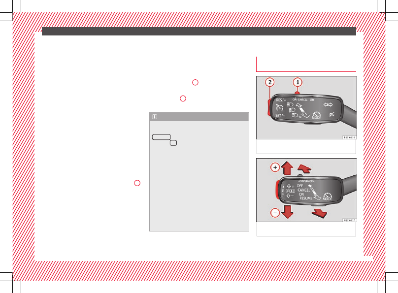
Cruise control

Operating the cruise control system
(CCS)*

Fig. 47 

On the left of the steering column:

switches and controls for operating the CCS

Fig. 48 

On the left of the steering column:

third lever to operate the CCS.

»

37

-------------------------------------------------------------------------------------------------------------------------------------------------------------

-------------------------------------------------------------------------------------------------------------------------------------------------------------

The essentials

Operation of the turn signal lever

Switching on the CCS: Move switch

››› 

Fig. 47


1

 to . The system is on. If no

speed has been programmed, the system will
not control it.

Activating the CCS: Press button 

››› 

Fig. 47

2

 in the  area. The current speed is

memorised and controlled.

Temporarily switching off the CCS: Move

switch 

››› 

Fig. 47


1

 to  or push the

brake. The cruise control system is switched
off temporarily.

Reactivating the CCS: Press button

››› 

Fig. 47


2

 in . The memorised speed

is saved and controlled again.

Increasing stored speed during CCS regula-

tion: press button 

2

 in . The vehicle ac-

celerates until the new stored speed.

Reducing stored speed during CCS regula-

tion: press button 

2

 in  to lower the

speed by 1 km/h (1 mph). Speed is reduced
until reaching the new stored speed.

Switching off the CCS: Move switch

››› 

Fig. 47


1

 to . The system is disconnec-

ted and the memorised speed is deleted.

Operation using the third lever

Switching on the CCS: move the third lever

to  

››› 

Fig. 48

. The system switches on but it

does not control the speed as no speed has
been programmed.

Activating the CCS: press the  

››› 

Fig. 48

button. It memorises and maintains the cur-
rent speed.

Temporarily switching off the CCS: move

the lever to  

››› 

Fig. 48

 and release it or

press the brake pedal. The cruise control sys-
tem is switched off temporarily.

Reactivating the CCS: move the lever to




››› 

Fig. 48

 and release it. The memo-

rised speed is saved and controlled again.

Switching off the CCS: move the third lever

to position  

››› 

Fig. 48

. The system is dis-

connected and the memorised speed is de-
leted.

››› 

 in Operation on page 197

››› 

page 197

38

-------------------------------------------------------------------------------------------------------------------------------------------------------------

-------------------------------------------------------------------------------------------------------------------------------------------------------------

The essentials

Warning lamps

On the instrument panel

Fig. 49 

Instrument panel, on dash panel

Red warning lamps

Central warning lamp: additional
information on the instrument pan-
el display

Parking brake on.

››› 

page 

174

››› 

page 

176


Do not continue driving!

The brake fluid level is too low or
there is a fault in the brake system.

Lit up or flashing:


Do not continue driving!

Fault in the steering.

››› 

page 

277

Driver or passenger has not fas-
tened seat belt.

››› 

page 

70

Use the foot brake!


Yellow warning lamps

Central warning lamp: additional
information on the instrument pan-
el display

»

39

-------------------------------------------------------------------------------------------------------------------------------------------------------------

-------------------------------------------------------------------------------------------------------------------------------------------------------------

The essentials

Front brake pads worn.

››› 

page 

177

it lights up: Fault in the ESC, or dis-
connection caused by the system.

flashes: ESC or ASR activated.

ASR manually deactivated.

››› 

page 

177

ESC in Sport mode.

ABS faulty or does not work.

Rear fog light switched on.

››› 

page 

135

lights up or flashes: fault in the
emission control system.

››› 

page 

190

it lights up: pre-heating of diesel
engine.

››› 

page 

191

flashes: fault in the diesel engine
management.



fault in the petrol engine manage-
ment.

››› 

page 

191

lights up or flashes: fault in the
steering system.

››› 

page 

277

Tyre pressure too low, or fault in
the tyre pressure monitoring sys-
tem.

››› 

page 

299

Fuel tank almost empty.

››› 

page 

106

Fault in airbag system and seat
belt tensioners.

››› 

page 

75

Lane Assist is switched on, but not
active.

››› 

page 

217

Other warning lamps

Left or right turn signal.

››› 

page 

135

Hazard warning lights on.

››› 

page 

139

Trailer turn signals.

››› 

page 

259

it lights up green: Auto Hold activa-
ted.

››› 

page 

195

it lights up green: Press the brake
pedal!
It blinks in green: the selector lever
locking button has not engaged.

››› 

page 

180

it lights up green: cruise control ac-
tivated or speed limiter switched
on and active.

››› 

page 

197

it blinks in green: the speed set by
the speed limiter has been excee-
ded.

it lights up green: Lane Assist is
switched on and active.

››› 

page 

217

Main beam on or flasher on.

››› 

page 

135

On the instrument panel display

Fig. 50 

On the instrument panel display: door

open.


Do not continue driving!

With the corresponding indica-
tion: door(s), rear lid or bonnet
open or not properly closed.

››› 

page 

116

››› 

page 

127

››› 

page 

286

Ignition: 


Do not carry on driv-

ing! Engine coolant level too low,
coolant temperature too high

››› 

page 

290

Flashing: Fault in the engine
coolant system.

40

-------------------------------------------------------------------------------------------------------------------------------------------------------------

-------------------------------------------------------------------------------------------------------------------------------------------------------------

The essentials


Do not continue driving!

Engine oil pressure too low. If
the warning lamp flashes, stop
driving, even if the oil level is
correct. Do not even run the en-
gine at idle speed!

››› 

page 

288

Fault in the battery.

››› 

page 

293

Driving light totally or partially
faulty.

››› 

page 

97

Fault in the cornering light sys-
tem.

››› 

page 

135

Diesel particulate filter blocked

››› 

page 

190

Level of windscreen washer fluid
too low.

››› 

page 

143

Flashing: Fault in the oil level de-
tection. Control manually.

››› 

page 

288

Ignition: Insufficient engine oil.

Fault in the gearbox.

››› 

page 

187

Light Assist on.

››› 

page 

136



Immobiliser active.


Service interval display

››› 

page 

36

Mobile telephone is connected
via Bluetooth to the original tele-
phone device.

››› 

Book-

let Radio

or

››› 

Book-

let Navi-
gation
system

Mobile telephone battery charge
meter. Available only for devices
pre-installed in factory.

Freezing warning. The outside
temperature is lower than +4°C
(+39°F).

››› 

page 

32

Start-Stop system activated.

››› 

page 

192

Start-Stop system unavailable.



Low consumption driving status

››› 

page 

31

On the instrument panel

Fig. 51 

Warning lamp for disabling the front

passenger airbag.




Front passenger front airbag is
disabled (  


 ).

››› 

page 

75




The front passenger front airbag
is activated (  


 ).

››› 

page 

75

››› 

 in Warning and control lamps on

page 111

››› 

page 110

Gearbox lever

Manual gearbox

Fig. 52 

Gear shift pattern of a 5 or 6-speed

manual gearbox

The position of the gears is indicated on the
gearbox lever 

››› 

Fig. 52

.

»

41

-------------------------------------------------------------------------------------------------------------------------------------------------------------

-------------------------------------------------------------------------------------------------------------------------------------------------------------

The essentials

Press the clutch pedal and keep your foot

right down.

Move the gearbox lever to the required po-

sition.

Release the clutch.

Selecting reverse gear

Press the clutch pedal and keep your foot

right down.

With the gearbox lever in neutral, push it

upwards, move it to the left as far as it will go
and then forwards to select reverse 

››› 

Fig. 52

R

.

Release the clutch.

››› 

 in Changing gear on page 180

››› 

page 180

Automatic gearbox*

Fig. 53 

Automatic gearbox: selector lever po-

sitions.

Parking lock
Reverse gear
Neutral (idling)
Drive (forward)
Tiptronic mode: pull the lever forwards
(

+) to go up a gear or backwards () to

go down a gear.

››› 

 in Selector lever positions on

page 181

››› 

page 180

››› 

page 42

P
R
N
D/S
+/–

Manual release of the selector lever

Fig. 54 

Selector lever: manual release from

position P.

Should the power supply be interrupted,
there is a manual unlocking device located
under the console of the selector lever, on
the right. Releasing the selector lever re-
quires a certain degree of practical skill.

Unlocking: use the flat part of a screwdriver

blade.

Removing the cover from the selector lever

Apply the handbrake  

››› 

 to ensure that

the car does not move.

Carefully pull the corners of the selector

lever boot and twist it upwards above the lev-
er handle.

42

-------------------------------------------------------------------------------------------------------------------------------------------------------------

-------------------------------------------------------------------------------------------------------------------------------------------------------------

The essentials

Releasing the selector lever

Using a screwdriver, press and hold the yel-

low unlocking tab sideways 

››› 

Fig. 54

.

Press the interlock button on the selector

lever and move the selector lever to posi-
tion 

N.

After carrying out the manual release, at-

tach the selector lever boot on the gearbox
console again.

If the power supply should ever fail (e.g. dis-
charged battery) and the vehicle has to be
pushed or towed, the selector lever must first
be moved to position 

N, after operating the

manual release mechanism.

WARNING

The selector lever may be moved out of posi-
tion P only when the handbrake is firmly ap-
plied. If this does not work, secure the vehi-
cle with the brake pedal. On a slope the vehi-

cle could otherwise start to move inadver-
tently after shifting the selector lever out of
position P - accident risk!

43

-------------------------------------------------------------------------------------------------------------------------------------------------------------

-------------------------------------------------------------------------------------------------------------------------------------------------------------

The essentials

Air conditioning

How does Climatronic* work?

Fig. 55 

In the centre console: Climatronic con-

trols

To switch a specific function on, press the ap-
propriate button. Press the button again to
switch off the function.

The LED on each control lights up to indicate
that the respective function of a control has
been switched on.

1

Temperature

The left and right sides can be adjusted separately: Turn the control to adjust the temperature

2

Fan

The power of the fan is automatically adjusted. The fan is also adjusted manually by turning the control.

3

Air distribution

The airflow adjusts automatically for comfort. You can also switch it on manually using the buttons 

3

.

4

Indications on the temperature display screen selected for the right and left sides.

44

-------------------------------------------------------------------------------------------------------------------------------------------------------------

-------------------------------------------------------------------------------------------------------------------------------------------------------------

The essentials



Defrost function

The air drawn in from outside the vehicle is directed at the windscreen and air recirculation is automatically switched off. To defrost the wind-
screen more quickly, the air is dehumidified at temperatures over approximately +3°C (+38°F) and the fan runs at maximum output.

The air is directed at the chest of driver and passengers by the dash panel air vents.

Air distribution towards the footwell.

Upward air distribution.

Heated rear window: this only works when the engine is running and switches off automatically after a maximum of 10 minutes.

Air recirculation

 

Seat heating buttons

Press the button to switch on or off the cooling system.




Press the button to make maximum cooling capacity available. The recirculation of air and the cooling system turn on automatically and air distri-
bution adjusts automatically to the position .



When the warning light for button  lights up, the settings on the driver side also apply to the passenger side. Press the button or the temper-
ature control on the passenger side



Automatic adjustment of temperature, fan, and air distribution. Press the button: the warning lamp on the button will light up .



Press the configuration button : the air conditioning operation menu will be displayed on the Easy Connect system screen.

Switching off

Turn the blower control to the  position or press the  button.

››› 

 in Introduction on page 160

››› 

page 160

45

-------------------------------------------------------------------------------------------------------------------------------------------------------------

-------------------------------------------------------------------------------------------------------------------------------------------------------------

The essentials

How does the manual air conditioning work*?

Fig. 56 

In the centre console: Manual air condi-

tioning controls

To switch a specific function on, press the ap-
propriate button. Press the button again to
switch off the function.

The LED on each control lights up to indicate
that the respective function of a control has
been switched on.

1

Temperature

Turn the control to adjust the temperature

2

Fan

Setting 0: blower and manual air conditioning switched off
Level 6: maximum fan level.

3

Air distribution

Rotate the continuous control to direct the airflow to the desired area.

Defrost function

The airflow is directed at the windscreen. Air recirculation is automatically switched off or is not switched on. Increase the fan power to clear the
windscreen of condensation as soon as possible. To dehumidify the air, the cooling system will automatically switch on.

The air is directed at the chest of driver and passengers by the dash panel air vents.

Distribution of air towards the chest and the footwell area.

46

-------------------------------------------------------------------------------------------------------------------------------------------------------------

-------------------------------------------------------------------------------------------------------------------------------------------------------------

The essentials

Air distribution towards the footwell.

Air distribution towards the windscreen and the footwell.

Heated rear window: this only works when the engine is running and switches off automatically after a maximum of 10 minutes.

Air recirculation

 

Seat heating buttons




Maximum cooling power. The recirculation of air and the cooling system turn on automatically and air distribution adjusts automatically to the
position 

››› 

 in Introduction on page 160

››› 

page 160

How does the heating and the fresh air system work?

Fig. 57 

In the centre console: heating system and

fresh air controls.

»

47

-------------------------------------------------------------------------------------------------------------------------------------------------------------

-------------------------------------------------------------------------------------------------------------------------------------------------------------

The essentials

To switch a specific function on, press the ap-
propriate button. Press the button again to
switch off the function.

The LED on each control lights up to indicate
that the respective function of a control has
been switched on.

1

Temperature

Turn the control to adjust the temperature. The temperature cannot be lower than that of the exterior air temperature, as this system cannot cool
or dehumidify the air

2

Fan

Setting 0: blower, heating and fresh air systems switched off
Level 6: maximum fan level

3

Air distribution

Rotate the continuous control to direct the airflow to the desired area.

Defrost function

The airflow is directed at the windscreen.

The air is directed at the chest of driver and passengers by the dash panel air vents.

Distribution of air towards the chest and the footwell area.

Air distribution towards the footwell.

Air distribution towards the windscreen and the footwell.

Heated rear window: this only works when the engine is running and switches off automatically after a maximum of 10 minutes

Air recirculation 

››› 

page 163

 

Seat heating buttons

››› 

 in Introduction on page 160

››› 

page 160

48

-------------------------------------------------------------------------------------------------------------------------------------------------------------

-------------------------------------------------------------------------------------------------------------------------------------------------------------

The essentials

Fluid Level control

Filling capacities

Tank level

Petrol and diesel
engines

50 l, of which, approx. 7 l reserve

Four-wheel drive vehicles:

55 l, of which approx. 8.5 l reserve

Capacity of the windscreen washer fluid container

Versions without
headlight washer
system

approx. 3 litres

Versions with
headlight washer
system

approx. 5 litres

Fuel

Fig. 58 

Fuel tank flap with tank cap attached.

The flap that covers the tank cap is unlocked
and locked automatically using the central
locking.

Opening the fuel tank cap

Open the fuel tank flap by pressing on the

left side.

Unscrew the cap by turning it to the left.

Place it in the space on the hinge of the

open flap 

››› 

Fig. 58

.

Closing the fuel tank cap

Unscrew the cap by turning it to the right as

far as it will go.

Close the lid.

››› 

 in Filling up on page 280

››› 

page 280

Oil

Fig. 59 

Engine oil dipstick.

Fig. 60 

In the engine compartment: Engine

oil filler cap

The level is measured using the dipstick loca-
ted in the engine compartment

››› 

page 286

.

The oil should leave a mark between zones

A

 and 

C

. It should never exceed zone 

A

.

Zone 

A

: Do not add oil.

»

49

-------------------------------------------------------------------------------------------------------------------------------------------------------------

-------------------------------------------------------------------------------------------------------------------------------------------------------------

The essentials

Zone 

B

: You can add oil but keep the level

in that zone.

Zone 

C

: Add oil up to zone 

B

.

Topping up engine oil

Unscrew cap from oil filler opening.

Add oil slowly.

At the same time, check the level to ensure

you do not add too much.

When the oil level reaches at least zone 

B

,

unscrew the engine oil filler cap carefully.

Oil properties

Engine type

Specification

Petrol without flexible service
interval

VW 502 00/VW 504
00

Petrol with flexible service in-
terval (LongLife)

VW 504 00

Diesel. Engines without Particu-
late filter (DPF)

VW 505 01/VW 506
01/VW 507 00

Diesel. Particulate Filter En-
gines (DPF).
With or without flexible service
interval (with and without Long-
Life)

a)

VW 507 00

a)

Only use recommended oils, otherwise you may damage the

engine.

Engine oil additives
No type of additive should be mixed with the
engine oil. The deterioration caused by these
additives is not covered by the warranty.

››› 

 in Changing engine oil on page 290

››› 

page 288

Coolant

Fig. 61 

Engine compartment: coolant expan-

sion tank cap.

The coolant tank is located in the engine
compartment 

››› 

page 286

.

When the engine is cold, replace the coolant
when the level is below .

Coolant specifications
The engine cooling system is supplied from
the factory with a specially treated mixture of
water and at least 40 % of the additive 

G13

(TL-VW 774 J), purple. This mixture gives the
necessary frost protection down to -25°C
(-13°F) and protects the light alloy parts of
the engine cooling system against corrosion.
It also prevents scaling and considerably rai-
ses the boiling point of the coolant.

To protect the cooling system, the percentage
of additive must always be at least 40 %,
even in warm climates where anti-freeze pro-
tection is not required.

If for weather reasons further protection is
necessary, the proportion of additive may be
increased, but only up to 60 %; otherwise an-
tifreeze protection will diminish and this will
worsen cooling.

When the coolant is topped up, use a mixture
of 

distilled water and at least 40 % of the

G13 or G12 plus-plus (TL-VW 774 G) additive
(both are purple) to obtain an optimum anti-
corrosion protection 

››› 

 in Topping up cool-

ant on page 291

The mixture of G13 with

G12 plus (TL-VW 774 F), G12 (red) or G11
(green-blue) engine coolants will significant-
ly reduce anti-corrosion protection and
should therefore be avoided 

››› 

 in Topping

up coolant on page 291

.

50

-------------------------------------------------------------------------------------------------------------------------------------------------------------

-------------------------------------------------------------------------------------------------------------------------------------------------------------

The essentials

››› 

 in Topping up coolant on page 291

››› 

page 290

Brake fluid

Fig. 62 

Engine compartment: brake fluid res-

ervoir cap

The brake fluid reservoir is located in the en-
gine compartment 

››› 

page 286

.

The level should be between the  and 
marks. If it is below , please visit a Techni-
cal Service.

››› 

 in Topping up brake fluid on

page 292

››› 

page 291

Windscreen washer

Fig. 63 

In the engine compartment: wind-

screen washer reservoir top.

The windscreen washer reservoir is located in
the engine compartment 

››› 

page 286

.

To top up, mix water with a product recom-
mended by SEAT.

In cold temperatures, add anti-freeze.

››› 

 in Checking and topping up the

windscreen washer reservoir on
page 292

››› 

page 292

Battery

The battery is located in the engine compart-
ment 

››› 

page 286

. It does not require

maintenance. It is checked as part of the In-
spection Service.

››› 

 in Important safety warnings for

handling a vehicle battery on page 294

››› 

page 293

51

-------------------------------------------------------------------------------------------------------------------------------------------------------------

-------------------------------------------------------------------------------------------------------------------------------------------------------------

The essentials

Emergencies

Fuses

Fuse location

Fig. 64 

 Left hand drive: fuse box cover in

the dash panel on the driver's side.  Right
hand drive: fuse box behind the glove com-
partment.

Fig. 65 

In the engine compartment: fuse box

cover

Underneath the dash panel (left hand drive)
The fuse box is located behind the storage
compartment 

››› 

Fig. 64

 .

Behind the glove compartment (right hand
drive)
The fuse box is located behind the glove
compartment 

››› 

Fig. 64

 . To access the fuse

box 

››› 

page 94

.

In the engine compartment
Press the locking tabs to release the fuse box
cover 

››› 

Fig. 65

.

Identifying fuses situated below the dash
panel by colours

Colour

Amp rating

Black

1

Colour

Amp rating

Purple

3

Light brown

5

Brown

7.5

Red

10

Blue

15

Yellow

20

White or transparent

25

Green

30

Orange

40

››› 

 in Introduction on page 93

››› 

page 93

52

-------------------------------------------------------------------------------------------------------------------------------------------------------------


Content      ..     1      2      3      4      ..