Seat Alhambra. Service Manual - part 9


  Index      Seat     Seat Alhambra. Service Manual


Search            copyright infringement  


Content      ..     7      8      9      10     ..


Seat Alhambra. Service Manual - part 9


-------------------------------------------------------------------------------------------------------------------------------------------------------------
Lights and visibility

Note

The vehicle battery will discharge and run

down if the hazard warning lights remain on
for too long (even with the ignition turned
off).

In some vehicles, the brake lights will flash

when braking abruptly at speeds of approxi-
mately 80 km/h (50 mph) to warn vehicles
travelling behind. If braking continues, the
hazard warning lights system will automati-
cally be turned on at a speed of less than ap-
proximately 10 km/h (6 mph). The brake
lights remain lit. Upon accelerating, the haz-
ard warning lights will be automatically
turned off.

Adhesive strips for headlights or ad-
justing headlights

In those countries where vehicles drive on
the other side of the road to the home coun-
try, the asymmetric dipped beam may dazzle
drivers of oncoming vehicles. Therefore,
when driving abroad, adhesive strips should
be attached to the headlights or the head-
lights should be adjusted accordingly.

The direction of the headlights can be adjus-
ted from the instrument panel, in the 

Tou-

rist light

 submenu of the 

Configura-

tion

 menu 

››› 

page 30

.

For those vehicles in which it is not possible
to adjust the headlights from the menu, ad-

hesive strips are used to cover certain parts
of the headlamp cover or the headlights may
be adjusted at a specialised workshop. For
further information, please refer to a special-
ised workshop. SEAT recommends visiting a
technical service.

Note

Use of the Tourist light option and the
adhesives on the headlights is only allowed if
they are to be used for a short period of time.
To modify the direction of the headlights per-
manently, please take the vehicle to a speci-
alised workshop. SEAT recommends visiting a
technical service centre.

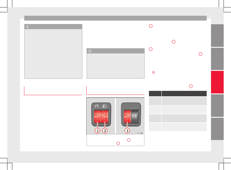
Headlight range control, lighting of
the instrument panel and controls

Fig. 141 

Next to the steering wheel: instru-

ment and switch lighting control 

1

 and

headlight range control 

2

1

 Instrument and switch lighting

When the headlights are switched on, the
brightness of the instruments and switch
lighting can be regulated by turning the
switch 

››› 

Fig. 141


1

.

2

 Headlight range control

The headlight range control 

››› 

Fig. 141


2

 is

modified according to the value of the head-
light beam and the vehicle load status. This
offers the driver optimum visibility and the
headlights do not dazzle oncoming drivers

››› 

.

The headlights can only be adjusted when
the dipped beam is switched on.

To reset, turn switch 

››› 

Fig. 141


2

:

Value

Vehicle load status

a)

Two front occupants, luggage compart-
ment empty

1

All seats occupied, luggage compartment
empty

2

All seats occupied, luggage compartment
full With trailer and minimum drawbar load

3

Driver only, luggage compartment full With
trailer and maximum drawbar load

a)

If the vehicle load does not correspond to those shown in the

table, it is possible to select intermediary positions.

»

133

Tec

hnic

al

 d

at

a

Adv

ic

e

Oper

ation

Emer

genc

ie

s

Saf

ety

-------------------------------------------------------------------------------------------------------------------------------------------------------------

-------------------------------------------------------------------------------------------------------------------------------------------------------------

Operation

Dynamic headlight range control
The control 

2

 is not mounted in vehicles

with dynamic headlight range control. The
headlight range is automatically adjusted ac-
cording to the vehicle load status when they
are switched on.

WARNING

Heavy objects in the back of vehicle may
cause headlight dazzle and distract other
drivers. This could result in a serious acci-
dent.

Adjust the light beam to the vehicle load

status so that it does not blind other drivers.

Interior and reading lights

Read the additional information carefully

››› 

page 26

Storage and luggage compartment lighting
When the glove compartment and the rear lid
are opened and closed, a light automatically
switches on or off.

Ambient lighting
The ambient lighting in the front covering of
the ceiling lights up the controls on the cen-
tre console from above when the side light or
dipped beam lights are on.

In addition, the lever on the door moulding
can also be illuminated.

Note

The reading lights go out when the vehicle is
locked, or a few minutes after the key is re-
moved from the ignition. This prevents the
vehicle's battery from discharging.

Visibility

Sun visors

Fig. 142 

Sun visor

Options for adjusting driver and front pas-
senger sun visors:

Lower the sun visor towards the wind-

screen.

The sun visor can be pulled out of its

mounting and turned towards the door

››› 

Fig. 142


1

.

Swing the sun visor towards the door, lon-

gitudinally backwards.

Vanity mirror light
There may be a vanity mirror, with a cover, on
the rear of the sun visor. When the cover is
opened 

››› 

Fig. 142


2

 a light comes on.

The lamp goes out when the vanity mirror
cover is closed or the sun visor is pushed
back up.

WARNING

Sun visors and sun blinds may reduce visibili-
ty when open.

Always roll or fold sun blinds and visors

away when not in use.

Note

The light above the sun visor automatically
switches off after a few minutes in certain
conditions. This prevents the battery from
discharging.

134

-------------------------------------------------------------------------------------------------------------------------------------------------------------

-------------------------------------------------------------------------------------------------------------------------------------------------------------

Lights and visibility

Rear side window sun blinds

Fig. 143 

On the rear right-hand window: sun

blind

The sun blinds for the vehicle interior are fit-
ted in the side panels of the windows.

Pull the sun blind by the handle 

››› 

Fig. 143

A

 up to the top.

Hook both rings of the fastening rod in the

spaces provided 

B

. Check that the sun blind

is securely hooked into the spaces provided
when it has been lowered 

B

.

To put the sun blind away, unhook it at the

top and lower by hand 

››› 

.

CAUTION

To prevent damage to the blind or the interior
trim, do not lower the sun blind “quickly”.

Windscreen wiper and window
wiper systems

Control lamp

It lights up

Windscreen wip-
er fluid level too
low

Top up the windscreen wiper reser-
voir as soon as possible

››› 

page 280

.

Several warning and control lamps light up
for a few seconds when the ignition is switch-
ed on, signalling that the function is being
verified. They will switch off after a few sec-
onds.

Window wiper lever

Read the additional information carefully

››› 

page 26

WARNING

Water from the windscreen washer water bot-
tle may freeze on the windscreen if it does
not contain enough anti-freeze, reducing for-
ward visibility.

In winter, ensure the windscreen washer

contains enough anti-freeze.

In cold conditions, you should not use the

wash/wipe system unless you have warmed
the windscreen with the ventilation system.

The antifreeze could freeze on the windscreen
and reduce visibility.

WARNING

Worn or dirty wiper blades reduce visibility
and increase the risk of accident and serious
injury.

Always replace damaged or worn blades or

blades which do not clean the windscreen
correctly.

CAUTION

In icy conditions, always check that the wiper
blades are not frozen to the glass before us-
ing the wipers for the first time. In cold
weather, it may help to leave the vehicle
parked with the wipers in service position

››› 

page 54

.

CAUTION

If the ignition is switched off while the wind-
screen wipers are on, the windscreen wipers
carry on wiping at the same level when the
ignition is switched back on. Ice, snow and
other obstacles may damage the windscreen
wiper and the respective motor.

Note

The windscreen wipers will only function

when the ignition is switched on and the re-
spective bonnet or rear lid are closed.

»

135

Tec

hnic

al

 d

at

a

Adv

ic

e

Oper

ation

Emer

genc

ie

s

Saf

ety

-------------------------------------------------------------------------------------------------------------------------------------------------------------

-------------------------------------------------------------------------------------------------------------------------------------------------------------

Operation

The interval wipe speed varies according to

the vehicle speed. The faster the vehicle is
moving, the more often the windscreen is
cleaned.

The rear wiper is automatically switched on

when the windscreen wiper is on and the car
is in reverse gear.

Windscreen wiper functions

Windscreen wiper performance in different sit-
uations

If the vehicle
is at a stand-
still

The activated position provisionally
changes to the previous position.

During auto-
matic wipe

The air conditioner comes on for ap-
proximately 30 seconds in air recircula-
tion mode to prevent the smell of the
windscreen washer fluid entering the
inside the vehicle.

For the inter-
val wipe

Intervals between wipes depend on the
vehicle's speed. The higher the vehicle
speed the shorter the intervals.

Heated windscreen washer jets
The heating only thaws the frozen jets, it
does not thaw the water in the washer hoses.
The heated windscreen washer jets automati-
cally adjust the heat depending on the ambi-
ent temperature when the ignition is switch-
ed on.

Headlight wash/wipe system
The headlight washers/wipers clean the
headlight lenses.

After the ignition is switched on, the first and
every fifth time the windscreen washer is
switched on, the headlights are also washed.
Therefore, the windscreen wiper lever should
be pulled towards the steering wheel when
the dipped beam or main beam are on. Any
incrusted dirt (such as insects) should be
cleaned regularly (e.g. when refuelling).

To ensure the headlight washers work cor-
rectly in winter, any snow which has got into
the bumper jet supports should be cleaned
away. If necessary, remove snow with an anti-
icing spray.

Note

The wiper will try to wipe away any obstacles
that are on the windscreen. The wiper will
stop moving if the obstacle blocks its path.
Remove the obstacle and switch the wiper
back on again.

Rain sensor*

Fig. 144 

Windscreen wiper lever: adjusting

the rain sensor 

A

Fig. 145 

Rain sensor sensitive surface

The rain sensor controls the frequency of the
windscreen wiper intervals, depending on
the amount of rain 

››› 

The sensitivity of the

rain sensor can be adjusted manually. Man-
ual wipe 

››› 

page 135

.

136

-------------------------------------------------------------------------------------------------------------------------------------------------------------

-------------------------------------------------------------------------------------------------------------------------------------------------------------

Lights and visibility

Move the lever to the required position

››› 

Fig. 144

:

Rain sensor off.
Rain sensor on; automatic wipe if neces-
sary.
Setting sensitivity level of rain sensor

Set control to the right: highly sensi-
tive.

Set control to the left: less sensitive.

When the ignition is switched off and then
back on, the rain sensor stays on and starts
operating again when the windscreen wipers
are in position 

1

 and the vehicle is travel-

ling at more than 4 km/h (2 mph).

Rain sensor modified behaviour
Possible causes of faults and mistaken read-
ings on the sensitive surface 

››› 

Fig. 145

 of

the rain sensor include:

Damaged blades: a film of water on the

damaged blades may lengthen the activation
time, reduce the washing intervals or result
in a fast and continuous wipe.

Insects: insects on the sensor may trigger

the windscreen wiper.

Salt on roads: in winter, salt spread in the

roads may cause an extra long wipe when the
windscreen is almost dry.

Dirt: dry dust, wax, coating on glass (Lotus

effect) or traces of detergent (car wash) may

0

1

A

reduce the effectiveness of the rain sensor or
make it react more slowly, later or not at all.

Cracked windscreen: the impact of a stone

will trigger a single wipe cycle with the rain
sensor on. Next the rain sensor detects the
reduction in the sensitive surface area and
adapts accordingly. The behaviour of the sen-
sor will vary with the size of the damage
caused by the stone.

WARNING

The rain sensor may not detect enough rain
to switch on the wipers.

If necessary, switch on the wipers manually

when water on the windscreen obstructs visi-
bility.

Note

Clean the sensitive surface of the rain sen-

sor regularly and check the blades for dam-
age 

››› 

Fig. 145

 (arrow).

To remove wax and coatings, we recom-

mend a window cleaner containing alcohol.

Rear vision mirror

Introduction

WARNING

The automatic anti-dazzle rear vision mirror
contains an electrolytic fluid which may leak
if the mirror is broken. This could cause irrita-
tion to the skin, eyes and respiratory organs.

The electrolytic fluid may cause irritation to

the skin, eyes and respiratory organs, partic-
ularly in individuals suffering from asthma or
other illnesses. Make sure that adequate
quantities of fresh air enter and leave the ve-
hicle if it is not possible to open all the doors
and windows.

If the electrolytic fluid comes into contact

with eyes or skin, wash the area for at least
15 minutes with plenty of water, and seek
medical advice.

If the electrolytic fluid comes into contact

with shoes or clothing, wash the area for at
least 15 minutes with plenty of water. Wash
shoes and clothing before wearing them
again.

If the electrolytic fluid is swallowed, wash

your mouth with plenty of water for at least
15 minutes. Do not try to provoke vomiting
unless recommended by a Doctor. Seek medi-
cal advice immediately.

»

137

Tec

hnic

al

 d

at

a

Adv

ic

e

Oper

ation

Emer

genc

ie

s

Saf

ety

-------------------------------------------------------------------------------------------------------------------------------------------------------------

-------------------------------------------------------------------------------------------------------------------------------------------------------------

Operation

CAUTION

In the event that an automatic anti-dazzle
rear vision mirror breaks, an electrolyte fluid
may leak. This liquid attacks plastic surfaces.
Therefore, it should be cleaned as fast as
possible with a damp sponge or similar.

Interior rear vision mirror

Fig. 146 

Manual anti-dazzle function for rear

vision mirror

Fig. 147 

Automatic anti-dazzle function for

rear vision mirror

The driver should always adjust the rear vi-
sion mirror to permit adequate visibility
through the rear window.

Manual anti-dazzle function for interior rear
vision mirror

Basic position: point the lever at the bot-

tom of the mirror forwards.

Pull the lever to the back to select the anti-

dazzle function 

››› 

Fig. 146

.

Automatic anti-dazzle function for interior
mirror
Key t

Fig. 147

:

Control lamp
Control
Light incidence sensor

1

2

3

This function can be activated and deactiva-
ted by pressing the rear-view mirror switch

››› 

Fig. 147


2

. When it is activated, the warn-

ing lamp lights up 

1

.

When the ignition is on, the sensor 

3

 auto-

matically moves the rear vision mirror to the
anti-dazzle position depending upon the in-
cidence of the light from behind.

The automatic anti-dazzle function is deacti-
vated when reverse gear is engaged or the in-
terior or reading lights are on.

Note

If the light is obstructed or prevented from
reaching the sensor, e.g. by the sun blinds,
the rear vision mirror with automatic anti-
dazzle function will not operate correctly.

138

-------------------------------------------------------------------------------------------------------------------------------------------------------------

-------------------------------------------------------------------------------------------------------------------------------------------------------------

Lights and visibility

Exterior mirrors

Fig. 148 

In the driver door: exterior mirror

controls

Read the additional information carefully

››› 

page 16

Turn the knob to the required position:

Electric folding exterior mirrors 

››› 

.

Switch on the exterior mirror heating This only
heats up if the ambient temperature is less
than +20°C (+68°F).

Adjust the left-hand exterior mirror by turning
the knob forward, backward, to the right or to
the left.

Adjust the right-hand exterior mirror by turning
the knob forward, backward, to the right or to
the left .

Zero position. Exterior mirror unfolded, exterior
mirror heating off, adjustment of exterior mir-
ror not possible.

Synchronised mirror adjustment

In the 

Settings - Convenience

 menu,

select whether or not the mirrors should
move in synchronisation 

››› 

page 26

.

Turn the knob to position 

L.

Adjust the left-hand exterior mirror. The

right exterior mirror will be adjusted at the
same time (synchronised).

If necessary the right exterior mirror adjust-

ment may need correcting. turn the control to
position 

R.

Automatic anti-dazzle exterior mirror, driver
side
The automatic anti-dazzle exterior mirror is
controlled in the same way as the automatic
anti-dazzle rear vision mirror 

››› 

page 138

.

Store the reverse settings for the passenger
exterior mirror

Select the vehicle key in which the setting

is to be stored.

Use this key to unlock the vehicle.

Connect the automatic parking brake.

Turn the exterior mirror knob to position 

R

(passenger side).

Switch the ignition on.

Move the gear lever to neutral.

Access the 

Settings

 menu on the instru-

ment panel display using the multifunction

steering wheel buttons and select 

Conven-

ience

.

Select the 

Rear vision mirror ad-

justment

 function (if it is already checked,

uncheck it and check the option again).

Select reverse gear.

Adjust the front passenger side exterior

mirror so that you can see, for example, the
kerb area.

The new position of the mirror will be stor-

ed automatically and allocated to the vehicle
key that was used to unlock the vehicle. For
vehicles with seat memory, please see

››› 

page 144

.

Activating the passenger exterior mirror set-
tings

Turn the exterior mirror knob to position 

R.

With the ignition switched on, select re-

verse gear.

The stored position of the passenger exteri-

or mirror for reverse gear is deleted when
driving forwards at 15 km/h (9 mph), or if the
knob is turned from position 

R to another po-

sition.

WARNING

Fold and unfold the exterior mirror, taking
care to avoid injuries.

Only fold or unfold the exterior mirror when

there is no-one in the way of the mirror.

»

139

Tec

hnic

al

 d

at

a

Adv

ic

e

Oper

ation

Emer

genc

ie

s

Saf

ety

-------------------------------------------------------------------------------------------------------------------------------------------------------------

-------------------------------------------------------------------------------------------------------------------------------------------------------------

Operation

When moving the mirror, take care not to

trap fingers between the mirror and the mir-
ror bracket.

WARNING

Failure to correctly estimate the distance of
the vehicle behind could lead to serious acci-
dent.

Rear-view convex or aspheric mirrors in-

crease the field of vision, however objects ap-
pear smaller and further away in the mirrors.

The use of these mirrors to estimate the

distance to the next vehicle when changing
lane is imprecise and could result in serious
accident.

If possible, use the rear vision mirror to es-

timate distances to vehicles behind you or in
other circumstances.

Make sure that the rear visibility is ade-

quate.

CAUTION

Before entering a car wash, always ensure

that the exterior mirrors are correctly folded
in.

Electrically-folding exterior mirrors should

not be folded and unfolded mechanically as
this may damage the electrical operation.

For the sake of the environment

The exterior mirror heating should be switch-
ed off when it is no longer needed. Other-
wise, it is an unnecessary fuel waste.

Note

The exterior mirror heating initially heats

up with a high power, after two minutes the
heat will depend upon the ambient tempera-
ture.

In the event of a fault, the electric exterior

mirrors can be adjusted manually by pressing
the edge of the mirror surface.

Seats and head restraints

Adjusting the seats and head
restraints

Manual adjustment of seats

Read the additional information carefully

››› 

page 13

WARNING

The safe driving chapter contains important
information, tips, suggestions and warnings
that you should read and observe for your
own safety and the safety of your passengers

››› 

page 56

.

WARNING

Adjust the front seats only when the vehi-

cle is stationary. Failure to follow this instruc-
tion could result in an accident.

Be careful when adjusting the seat height.

Careless or uncontrolled adjustment can
cause injuries.

The front seat backrests must not be re-

clined for driving. Otherwise, seat belts and
the airbag system might not protect as they
should in the case of an accident, increasing
risk of injury.

140

-------------------------------------------------------------------------------------------------------------------------------------------------------------

-------------------------------------------------------------------------------------------------------------------------------------------------------------

Seats and head restraints

Electric driver's seat adjustment*

Read the additional information carefully

››› 

page 14

WARNING

Using the front electric seats in a careless or
uncontrolled manner may lead to severe inju-
ries.

The front seats can also be electrically ad-

justed when the ignition is switched off. Nev-
er leave children or disabled people alone in
the vehicle.

In the event of an emergency, stop electri-

cal adjustment by pressing any button.

CAUTION

So as not the damage the electrical compo-
nents of the front seats, do not kneel on the
seats or apply specific pressure to one point
of the seat or seat backrest.

Note

It may not be possible to electrically adjust

the seat if the vehicle battery is very low.

Seat adjustment is stopped when the en-

gine is started.

Adjusting the rear seats

Fig. 149 

Adjusting rear seats

Function

Necessary operations

1

 Adjusting the

seat backrest.

Pull the lever and adjust the seat
backrest to the required position

››› 

. The seat backrest must be

engaged when the lever is re-
leased! There is a handle instead
of the lever on the third row of
seats and on the central seat of
the second row. It is used in the
same manner as the lever.

2


On the second

row of seats only:
move the seat
backwards or for-
wards.

Pull the lever and move the seat
forwards or backwards. The seat
must be engaged when the lever
is released!

CAUTION

Tilting the seat backrest of the second row

of seats fully back could damage the luggage

compartment tray. Remove the tray before
adjusting the seat backrest.

Objects in the luggage compartment could

cause damage when moving the rear seats
forwards or backwards.

141

Tec

hnic

al

 d

at

a

Adv

ic

e

Oper

ation

Emer

genc

ie

s

Saf

ety

-------------------------------------------------------------------------------------------------------------------------------------------------------------

-------------------------------------------------------------------------------------------------------------------------------------------------------------

Operation

Adjustment of the head restraints

Fig. 150 

A: Adjust the head restraints with no

possibility of lengthways direction adjust-
ment; B: Adjust the head restraints with
lengthways direction adjustment

Fig. 151 

Adjust the head restraints in the sec-

ond or third row of seats

Read the additional information carefully

››› 

page 15

All seats are equipped with a head restraint.

Adjusting height

Raise the head restraint in the direction of

the arrow or lower it 

››› 

Fig. 150

 or 

››› 

Fig. 151

1

 with the button pressed 

››› 

 in Removing

and installing the head restraints on
page 144

.

The head restraint must engage securely in

position. There are three possible positions
on the second row of seats and two possible
positions on the third row of seats.

Adjusting the front head restraints

Push the head restraint forward in the di-

rection of the arrow or backward 

››› 

Fig. 150

1


B with the button pressed.

The head restraint must engage securely in

position.

Correct adjustment of head restraints
Adjust the head restraint so that its upper
edge is at the same level as the top of your
head, or as close as possible to the same lev-
el as the top of your head and under no cir-
cumstances below eye level. Keep the back
of your neck as close as possible to the head
restraint.

Adjusting the head restraint for short people
Lower the head restraint completely, even if
your head is below its upper edge. When the
head restraint is at its lowest, it is possible
that a small gap remains between it and the
seat backrest.

Adjusting the head restraint for tall people
Raise the head restraint completely.

142

-------------------------------------------------------------------------------------------------------------------------------------------------------------

-------------------------------------------------------------------------------------------------------------------------------------------------------------

Seats and head restraints

Removing and installing the head re-
straints

Fig. 152 

A: Fitting the head restraints with no

possibility of lengthways direction adjust-
ment; B: Fitting the head restraints with
lengthways direction adjustment

Fig. 153 

Fitting the head restraints in the sec-

ond or third row of seats

All seats are equipped with a head restraint.

Removing the front head restraints in vehi-
cles without the lengthways direction ad-
justment of the head restraints

If necessary, adjust the seat backrest so

that the head restraint can be fitted.

Push the head restraint up as far as it will

go 

››› 

.

Pull out the head restraint pressing the but-

ton completely 

››› 

Fig. 152


1


A.

Fitting the front head restraints in vehicles
without the lengthways direction adjustment
of the head restraints

Correctly place the head restraint into the

guides on the seat backrest and insert it.

Completely press the button 

1


A and push

the head restraint downwards.

Adjust the head restraint according to the

correct seat position and secure it

››› 

page 142

.

Removing the front head restraints in vehi-
cles with the lengthways direction adjust-
ment of the head restraints

If necessary, adjust the seat backrest so

that the head restraint can be fitted.

Push the head restraint up and backward

as far as it will go 

››› 

.

Place a flat object, e.g. a plastic card 

2


B,

on both sides between the seat backrest cov-
er and the end protector of the seat backrest
retaining bar and unlock the retaining bars
with a little pressure.

Completely pull out the head restraint.

Fitting the front head restraints in vehicles
with the lengthways direction adjustment of
the head restraints

Pull out the two retaining bars from the

head restraint as far as possible.

Correctly place the head restraint into the

guides on the seat backrest and insert it.

Push the head restraint down as far as pos-

sible until the two retaining bars are secured.

Adjust the head restraint according to the

correct seat position and secure it

››› 

page 142

.

»

143

Tec

hnic

al

 d

at

a

Adv

ic

e

Oper

ation

Emer

genc

ie

s

Saf

ety

-------------------------------------------------------------------------------------------------------------------------------------------------------------

-------------------------------------------------------------------------------------------------------------------------------------------------------------

Operation

Removing the head restraints from the sec-
ond and third row of seats

Fold the backrest of the rear seat forwards

››› 

page 152

.

Push the head restraint up as far as it will

go 

››› 

.

Pull out the head restraint 

››› 

Fig. 153


1

with the button pressed.

Fold the backrest of the rear seat back-

wards until it is engaged.

Fitting the head restraints in the second and
third row of seats

Fold the backrest of the rear seat forwards

››› 

page 152

.

Insert the head restraint into the guides on

the seat backrest.

Push the head restraint down while press-

ing the button 

1

.

Fold the backrest of the rear seat backward

again until it is engaged.

Adjust the head restraint to the correct po-

sition 

››› 

page 142

.

WARNING

Travelling with the head restraints removed
or improperly adjusted increases the risk of
severe or fatal injuries in the event of acci-
dents and sudden braking or manoeuvres.

Always fit and adjust the head restraint

properly whenever a person is occupying a
seat.

Refit any removed head restraints immedi-

ately so that passengers are properly protec-
ted.

All vehicle occupants must correctly adjust

the head restraint according to their height to
reduce the risk of back injuries in the event of
an accident. The upper edge of the head re-
straint must be as close as possible to the
same level as the top of your head and under
no circumstances below eye level. Keep the
back of your neck as close as possible to the
head restraint.

Never adjust the head restraint while the

vehicle is in motion.

CAUTION

When removing and fitting the head restraint,
make sure it does not hit the headliner of the
vehicle or the front seat backrest. Otherwise,
the interior roof and other parts of the vehicle
could be damaged.

Seat functions

Seat heating*

Fig. 154 

Detailed view of the centre console:

front seat heating controls, here with the sec-
ond temperature level set

Fig. 155 

Detailed view of the centre console:

controls for the front seat heating in vehicles
equipped with Climatronic

144

-------------------------------------------------------------------------------------------------------------------------------------------------------------

-------------------------------------------------------------------------------------------------------------------------------------------------------------

Seats and head restraints

The seat cushions can be heated electrically
when the ignition is switched on. The back-
rest is also heated in some versions.

Switch off seat heating if there is nobody in
the seat.

Function

Action 

››› 

Fig. 154

››› 

Fig. 155

Activate

Press button . Seat heating is
switched on fully.

Adjusting the
heating output

Keep pressing button  until the re-
quired intensity is set.

Deactivating

Keep pressing button  until all of
the lights are switched off

››› 

Fig. 154

››› 

Fig. 155

.

WARNING

Inappropriate use of the seat functions can
cause severe injuries.

Assume the proper sitting position before

your trip and remain in it throughout. This al-
so applies to the other occupants.

Only adjust the seat position memory when

the vehicle is stationary.

Only switch the lumbar massage function

on and off when the vehicle is stationary.

Keep hands, fingers, feet and other limbs

away from the seat operating and adjustment
radius.

WARNING

People whose pain and temperature thresh-
old has been affected by some kind of medi-
cine, paraplegia or chronic illness (e.g. diabe-
tes) may sustain burns to the back, buttocks
and legs from using the seat heaters that
may lead to a long healing process or that
may never completely heal. Seek medical ad-
vice if you have doubts regarding your health.

People with limited pain and temperature

thresholds must never use seat heating.

CAUTION

To avoid damaging the heating elements of

the seat heaters, please do not kneel on the
seat or apply sharp pressure to a single point
on the seat cushion or backrest.

Liquids, sharp objects and insulating mate-

rials on the seat could damage the seat heat-
ing.

In the event of smells, switch off the seat

heating immediately and have the unit in-
spected by a specialised workshop.

For the sake of the environment

The seat heating should remain on only when
needed. Otherwise, it is an unnecessary fuel
waste.

Lumbar massage function*

Fig. 156 

On the side of the front seat: lumbar

massage function switch.

During the massage operation, the lumbar
support will move in a way that massages the
lumbar area of the back. While it is operat-
ing, the arch of the lumbar support can be
adjusted using the corresponding control
based on your personal preferences

››› 

page 57

.

Connection

Press the button 

 in the control panel of

the seat.

Disconnection

Press the button 

 again in the control

panel of the seat.

»

145

Tec

hnic

al

 d

at

a

Adv

ic

e

Oper

ation

Emer

genc

ie

s

Saf

ety

-------------------------------------------------------------------------------------------------------------------------------------------------------------

-------------------------------------------------------------------------------------------------------------------------------------------------------------

Operation

Automatic off

The lumbar massage will disconnect auto-

matically after approx. 10 minutes.

Seat with position memory*

Fig. 157 

Memory buttons on the outside of

the driver seat

Memory buttons
Individual settings for the driver seat and the
exterior mirror can be assigned to each mem-
ory button.

Storing exterior mirror settings for driving
forwards

Connect the automatic parking brake.

Move the gear lever to neutral.

Switch the ignition on.

Adjust the front seat and the exterior mir-

rors.

Keep the 

SET

 button held down for more

than one second 

››› 

Fig. 157

.

Press the required memory button for the

following 10 seconds. An audible warning
confirms the settings have been stored.

Storing front passenger exterior mirror set-
tings for driving in reverse gear

Connect the automatic parking brake.

Move the gear lever to neutral.

Switch the ignition on.

Press the required memory button.

Select reverse gear.

Adjust the front passenger side exterior

mirror so that you can see, for example, the
kerb area.

The new position of the mirror will be stor-

ed automatically and allocated to the vehicle
key that was used to unlock the vehicle.

Activating exterior mirror settings

With the driver door open and the ignition

turned off, push the memory button of the
corresponding door briefly.

OR: with the ignition switched on, hold in

the corresponding memory button until the
memorised position is reached.

To activate the memory function of the vehi-
cle key
Important: a position must be memorised in
the memory.

Open the driver-side door.

Press and hold any memory button.

Within the following three seconds, push

the button 

 to open the vehicle on the vehi-

cle key. An audible warning confirms the set-
tings have been activated.

Adjusting the wing mirrors for driving and
assigning driver seat settings to a vehicle
key

Activate the memory function of the vehicle

key

Adjust the front seat and the exterior mir-

rors.

Lock the vehicle. The settings are assigned

to the vehicle key.

To deactivate the memory function of the ve-
hicle key
Important: a position must be memorised in
the memory.

Press and hold the 

SET

 button.

Within the following 10 seconds, push the

open button 

 on the vehicle key. An audi-

ble warning confirms the settings have been
deactivated.

146

-------------------------------------------------------------------------------------------------------------------------------------------------------------

-------------------------------------------------------------------------------------------------------------------------------------------------------------

Seats and head restraints

Initialising the seat position memory
The position memory system must be restar-
ted if, for example, the driver seat has been
changed.

Restarting deletes all memories and assign-
ments for the seat with position memory. The
memory buttons can then be reprogrammed
and the vehicle keys re-assigned.

Open the driver door and do not get into

the vehicle.

Operating the seat settings from outside

the vehicle.

Move the angle of the seat backrest com-

pletely forwards.

Release the control to set the angle and

then press again until an audible warning is
heard.

Note

The front passenger side exterior mirror auto-
matically changes from the position stored
for reversing as soon as the vehicle moves
forward at a speed of at least 15 km/h
(9 mph) or when the gear selection lever is
changed to a position other than R.

Convenient entry function for the third
row of seats

Fig. 158 

Second row of seats: convenient en-

try function controls

The outer seats of the second row can be fol-
ded to make it easier to get in and out of the
third row of seats.

Folding down the second row seats

If necessary, open the belt loop and wind

up the seat belt by hand.

If necessary, remove the side head restraint

of the integrated child seat 

››› 

page 78

.

If necessary, raise the armrests.

Remove any objects located in the footwell

of the second row of seats, where applicable

››› 

.

Push the head restraint down as far as it

will go 

››› 

page 57

.

Push the lever 

››› 

Fig. 158


1

 forwards and

fold the backrest of the rear seat. This seat
folds forward completely 

››› 

 and can still

be moved further forward.

Always take care when entering and leav-

ing the vehicle 

››› 

.

Repositioning the seat in the second row

Lift the backrest of the rear seat in an up-

right position. The entire seat folds back-
wards 

››› 

.

Make sure that the rear seat is securely en-

gaged so that the seat belts can provide
proper protection in the rear seats. The red
mark 

››› 

Fig. 158


2

 should no longer be visi-

ble 

››› 

 in Folding down rear seats to create

load space on page 154

.

Emergency exit function
If the lever 

››› 

Fig. 158


1

 does not work, e.g.

after an accident, the seats on the second
row can be folded forwards from the third row
to allow vehicle occupants of the third row of
seats to get out of the vehicle 

››› 

.

Pull the handle 

››› 

Fig. 158


3

 back and

fold the backrest of the rear seat. The com-
plete rear seat folds forward 

››› 

.

»

147

Tec

hnic

al

 d

at

a

Adv

ic

e

Oper

ation

Emer

genc

ie

s

Saf

ety

-------------------------------------------------------------------------------------------------------------------------------------------------------------

-------------------------------------------------------------------------------------------------------------------------------------------------------------

Operation

WARNING

Careless or uncontrolled use of the conven-
ient entry assistant may result in severe in-
jury and accident.

Never use the convenient entry function

when the vehicle is in motion.

Avoid trapping or damaging the seat belt

when folding the rear seats back.

Keep your hands, fingers, feet and other

body parts out of the hinges and the seat
locking mechanism when folding and unfold-
ing.

Mats or other objects can be caught in the

hinges of the seat backrests or rear seat. This
could prevent the seat backrest from locking
safely when positioned upright.

All seat backrests must engage correctly for

the seat belts on the rear seats to work prop-
erly. When the seat backrest of an occupied
seat is not correctly locked in place, the pas-
senger can be thrust forward with the seat
backrest in case of sudden braking, sudden
manoeuvres or an accident.

A red mark on the side of the seat

››› 

Fig. 158


2

 indicates that the seat back-

rest is not engaged. The mark is no longer
visible when it is correctly engaged.

If the seat backrest or seat are folded down

and are not correctly locked in place, no pas-
senger should use them.

When getting in or out, never lean or hold

onto the folded seat on the second row of
seats.

WARNING

If child seats are fitted to all the seats in the
second row then it is possible that the seats
of this row cannot be folded down from the
third row of seats in the event of an accident.
In the event of an emergency, passengers in
the third row of seats will not be able to leave
the vehicle or to help themselves.

Child seats should not occupy all the seats

of the second row if other passengers are to
occupy the third row.

CAUTION

Before folding down the rear seat backrest

for returning it to its position, adjust the front
seats so that the head restraints and seat
backrests do not hit each other when folding
and unfolding.

Any objects located in the footwell of the

second row of seats may be damaged on fold-
ing the rear seat forwards. Remove any ob-
jects before folding the seat down.

Folding the backrest of the front pas-
senger seat*

Fig. 159 

Folding the backrest of the front pas-

senger seat

Fig. 160 

Unlocking the folding backrest of the

front passenger seat

The backrest of the front passenger seat can
be folded and locked horizontally.

148

-------------------------------------------------------------------------------------------------------------------------------------------------------------


Content      ..     7      8      9      10     ..