Haima S5. Chassis System. Service Manual - part 2


  Index      Haima     Haima S5. Chassis System. Service Manual


Search            copyright infringement  


Content      ..      1      2      3      ..


Haima S5. Chassis System. Service Manual - part 2


Wheels and tires 2C-5 


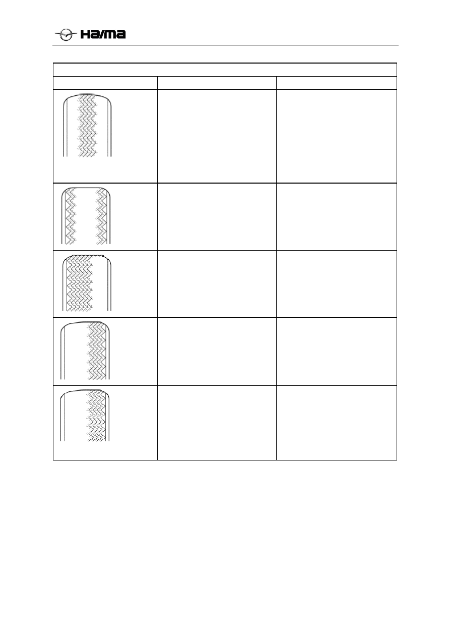
Irregular or excessive wears of tire


Fault


Possible causes


Corrective measures


  Overlow tire pressure 

 Improper tire rotation


  Adjust the tire pressure. 

 Rotate the tire.


  Overhigh tire pressure 

 Improper tire rotation


  Adjust the tire pressure. 

 Rotate the tire.


 Improper toe-in


  Adjust the toe-in.


 Reverse toe-in


  Adjust the toe-in.


  Improper kingpin caster angle 

or improper front-wheel 
camber 

 Suspension failure 

  Improper wheel balance 

 Improper tire rotation


 Check the steering knuckle, 

control connecting rod, drive 
shaft and suspension. Replace 
if necessary. 

  Adjust the balance of wheel. 

 Rotate the tire.


-------------------------------------------------------------------------------------------------------------------------------------------------------------


Wheels and tires 2C-6 

Repair instructions 

Wheel repair instructions 


I. 

Sequence of removal 

  Remove the hub nut; 

  Lift the wheel stably. 

Note:  don’t loosen the tightened wheel by heating 
it. It will shorten the service life of wheel, hub nut 
and wheel bearing. Excessive force application, e.g. 
hitting the wheel or tire, will also cause the 
damages, which can’t be recovered. It’s allowed to 
hit the sides of wheel slightly with a hand or 
rubber hammer. 

③  

Remove the wheel. 

If it’s difficult to remove the wheel from the 
vehicle, it may be caused by the existence of 
sundries or excessive close fit among the wheel 
middle holes, nuts and hubs. At this time, the 

wheel can be removed from the vehicle by 
adopting the following methods: 

A.  Re-tighten any influenced hub nut, and then 

turn the hub nut two circles in its loosening 
direction. 

B.  Lower the vehicle, try to shake the vehicle, 

and adopt the weight of one or several 
persons to loosen the wheel.  

C.  Lift up the vehicle again, and then remove the 

wheel. 

Note:  don’t apply the lubricating oil to vertical 
surface of wheel and hub (or brake disc), because 
the existence of lubricating oil in these positions 
will lead to the wheel loosening when the vehicle 
is driven, control failure of vehicle and even 
serious accidents. The lubricating oil is not good 
for removal of tightened wheel. If the lubricating 
oil is required, don’t apply too much oil, and only 
to the centerhole area of wheel. 

II.  Sequence of installation 

Note:  before installing the wheel, please remove 
the sundries from the mounting faces of wheel, 
brake drum and hub with a hairbrush. If the surface 
contact is poor during the installation, it will 
loosen the hub nut. While the vehicle is driving, 
there may be a risk of disengaging the wheel from 
the vehicle. The hub nut must be tightened as per 
the specified torque, but its tightening force shall 
not be excessive, thus the bends of wheel, brake 
drum or hub can be avoided. 

  Install the wheel. 

  Install the hub nuts in diagonal order. Don’t 

tighten the hub nut. 

  Lower the vehicle. 

 Tighten 

it. 

Tighten the hub nuts up to the torque of 100 to 120 
N.m (73.3 to 88.3 lb-ft). 

 Wheel 

balance 

Measure the balance of wheel with an automatic 
balancing machine. The balancing machine is 
convenient in operation, its static and dynamic 
balance can be also measured. Unlike the balance 
of vehicle, don’t calibrate the unbalance of vehicle, 
brake drum or hub. This defect can be resolved by 
precision. During the balancing work, make the 
taper part through the wheel center hole to fix the 
wheel, and don’t do so through the mounting hole 
of hub nut. 

  Calibrate the unbalanced tire. 

Provide two methods to calibrate the unbalanced 

-------------------------------------------------------------------------------------------------------------------------------------------------------------


Wheels and tires 2C-7 

tire. 

One method is to fix the tire through this automatic 
device, and then hit small yellow rubber blocks on 
both sides of tire tread. Such calibration method is 
usually permanent. 

If it’s well handled, it won’t influence its 
appearance or tire service life. 

It’s not recommended to calibrate any tire with a 
blade-shape machine, because it can reduce the 
service life of tire tread, and the tire can’t be 
permanently calibrated.  

The other method is to remove the tire, and then 
turn it by 180

ﹾ on the rim. The unbalance of wheel 

or tire must be known before doing so, because 
this method can ensure the balance of its assembly. 

 Installation of tire and wheel 

The tire and wheel shall be installed in the 
assembling workshop. During the installation, 
install them by aligning the radial hard point or 
heavy balancing point of tire to the radial dot or 
light balancing point of wheel. 

The heavy balancing point of tire is marked with a 
red dot during the start of its production, or marked 
on the tire side with a label. 

The light balancing point of wheel is located at the 
inflating valve. 

Before installing the tire and wheel, scribe a line 
on the tire and inflating valve to ensure that they 
can be installed in the same position during the re-
installation.  

The quality of spare tire and original tire shall be 
the same, and their heavy and light points shall be 
marked with the same method. 

Instructions 

Instructions for tire size and air pressure 

Inflation pressure 


Front Rear 


Tire Wheel 

kPa psi kPa psi 

215/65 

R16 

16×5. 5J 

aluminum) 

230 33 210 31 

215/60 

R17 

17×6.5J 

(aluminum) 

230 33 210 31 


Instru`ctions for converting the inflation 

pressure


kPa psi  kPa  psi  kPa psi

140 20  186  27  234 34

145

21 193 28 241 

35

152

22 200 29 248 

36

159

23 207 30 276 

40

166

24 214 31 310 

45

172

25 220 32 345 

50

179

26 228 33 379 

55

Instructions for tightening torque 

Type


N.m


Ib.Ft


Ib.In


Hub 

nut(aluminu

m alloy 

wheel)


100 to 

120


66 to 81


Hub 

nut(steel 

wheel)


100 to 

120


66 to 81


-------------------------------------------------------------------------------------------------------------------------------------------------------------

                                                                                                                           Wheels and tires 

2C-8 

Installation / disassembly of tire pressure 
monitoring hosts 

1. Remove the battery negative connection

.


2.


Disconnect the tire pressure monitoring host

.


3. Use a wrench to tire pressure monitoring hosts and 

mounting bracket removed from the car body. 

4. In the order shown in the table demolition; 
5. According to and reverse order of removal 

installation

.


Tire pressure sensor installation / removal 

1. Remove the tire; 
2. Remove the tire casing: 
3.  In the order shown in the table demolition; 
4. According to and reverse order of removal 
installation

.


1 Dust cup 

2 Hex  nuts 

3 Metal gasket 

4 Sensor 


1 Harness 

connector 

2 Mounting 

bolts 

3  tire pressure monitoring host (with 

bracket) 

-------------------------------------------------------------------------------------------------------------------------------------------------------------

                                                                                                                       Wheels and tires 

2C-9 

Precautions 

1.Driving the process, as in the present system alarm Do not panic, to avoid unnecessary accidents, please check 

to make sure the safety zone by car to.。 

2.The system can effectively vehicle tire pressure and temperature to be monitored, but can not prevent the 

occurrence of unexpected accident; the user should ensure that the car with the help of the system in the 
normal tire pressure and temperature conditions. 

3.To ensure the safety of you and your family do not use more than the life or have been badly worn tires, tires 

should be replaced with new tires require timely. 

4.Perfusion certain chemicals (such as leak-proof glue, etc.) can damage the sensor within the tire manufacturer 

will not be affected for such systems to provide quality assurance. 

5.When the vehicle is running, such as a radio frequency transmitter to nearby towers, radio stations, military 

region, airports and other areas surrounding the complex electromagnetic environment, it may cause the 
system wireless communication signal interference, causing the system to issue a warning abnormal 
communication tips. When the vehicle left these areas may automatically resume normal operation. 

6.When the radiation inside the vehicle fitted with a large electronic products, or install wireless transmission 

continued working device, are likely to affect the normal reception of the data in this system, cause the system 
to communicate warning exceptions. 

7.Vehicles may generate pressure alarm from extremely cold surroundings into a very hot surroundings, or from 

extreme heat to extreme cold surroundings into the surrounding environment, with tire gas expansion and 
contraction. 

8.Tire pressure sensors powered by battery when the vehicle is used in the extremely cold environments, you 

may discharge the battery by temperature influence diminished capacity, resulting in weakening of sending a 
warning signal of the sensor caused by communication failure, when the vehicle is running for some time as 
the tire temperature rises high, the failure to eliminate themselves.。 

9.Tire pressure sensor when the vehicle is stopped, to save energy automatically enters a low power state. 

If the tire pressure changes can be updated when there is 10KPA offer 20 seconds of data once, and also the 
ignition switch is turned on, tire pressure host in the receiving state.  

If the parking subtraction tire pressure, tire pressure monitor can not update the data, the user starts the 
vehicle, when the vehicle exceeds 25Km / h, pressure data will be automatically updated. 


-------------------------------------------------------------------------------------------------------------------------------------------------------------

                                                                                                                       Wheels and tires 

2C-10 

Function Display Interface


Function Display Interface Description


   When you open the ACC, tire pressure host sends data to the instrument display.  

The following is the reference pattern: 

1Normal  displayinstrument processing 


2Show Gap 

   Because the sensor test error, error associated requirements in line with GB T 26149-2010; 

1. The ambient temperature (0 ~ 50 ℃) error: ± 8.5KPa; 
2. Other temperature (-40 ~ 105 ℃) error: ± 17.5KPa; 
Note: When the tire pressure data changes 10KPA still more in order to have updated, as you can not receive 
IGN OFF. 

  When the test pressure, to confirm whether the data is updated, the following methods: 

1: IGN ON position, using the learning is activated once the tires; 
2: exercising the vehicle enters a state (25km / h or higher) and held for 5 minutes. 
The data in the above manner is sent to the host for the tire sensor data updates. 

3Undervoltage alarm display   

 Indicate the location of undervoltage tires. 
When the car tires of one or more tire pressure is below 170kpa, the display will be shown prompted alarm.
(Shown for reference only) 


-------------------------------------------------------------------------------------------------------------------------------------------------------------

                                                                                                                       Wheels and tires 

2C-12 

4. High pressure alarm display


   When the car tires of one or more tire pressure is higher than 290kpa, the display will be shown prompted alarm.  

(Shown for reference only) 


5.  Fault alarm display 

Vehicle exercising greater than 25 km / h, when the system itself is faulty, damaged or did not match, such as        
sensors, tire pressure system should send alarm signals within 15 min, the display will be shown prompted 
alarm. 

       Pictured: front left tire failure   (Shown for reference only) 


 6.  Fast leak alarm display 

Exercise of the vehicle is greater than 25 km / h, when the tire in the tire pressure of one or more    greater      
than 30kpa / min rate is lowered, 
Issued within TPMS60s fast leak detection alarm signal 60s,, such as continuous pressure does not drop, or 
pressure rise, canceled fast leak alarm. 

(Shown for reference only) 


7.  about tire pressure difference is too big alarm display 

Two vehicle axle rear tire pressure or tire pressure difference between the two exceeds 0.6 kpa, the display 
will be shown prompted alarm. 

(Shown for reference only) 

-------------------------------------------------------------------------------------------------------------------------------------------------------------

                                                                                                                       Wheels and tires 

2C-12 


Troubleshooting


1: undervoltage alarm


   Cause: The weather temperature is too low or leak, resulting in low tire pressure warning. 

Troubleshooting: Vehicle placed in ACC status, filling the tires to normal pressure, the system will  disarm the 
alarm, such as the fault persists, you can exercise the vehicle to 25 km / h and the duration of 10 minutes, the 
fault is automatically lifted.


2: The emergence of high-pressure alarm


Cause: The weather temperature is too high or the tires, too high, causing the tire pressure is too high alarm. 
Troubleshooting: ACC status of the vehicle is placed on reducing gas to the normal tire pressure, the system 
will disarm the alarm, such as the fault persists, you can exercise the vehicle to 25 km / h and the duration of 10 
minutes, the fault is automatically lifted. 

3: Fault Alarm


Reason: Vehicles subject to electromagnetic interference, sensor does not match, the sensor battery is low or the 
sensor is damaged, resulting in failure alarm. 
Troubleshooting: 
3.1): Vehicle by environmental electromagnetic interference, such as radio or military exercises near the vehicle   
outside interference can be exercised to return to normal; 
3.2): the vehicle is the vehicle electromagnetic interference: If the vehicle installation DVD, tachograph, 
walkie-talkies and other electronic devices excessive electromagnetic radiation, will 
Tire pressure system for communication frequency interference, causing the tire pressure sensor signals the host 
can not receive automatic alarm. Disconnect the power supply related electronic equipment for testing, such as 
tire pressure back to normal, then the excessive electromagnetic related equipment failed to be removed.


3.3): The sensor does not match, the system automatically normal alarm. 
Use vehicle diagnostic, click interface makes tire pressure tire pressure to match the host into the matching state; 

Learn collected using a handheld tire sensor ID, tire pressure and transmit to the host, as follows:

a. the vehicle is at a standstill, holding learner key positive press LF wake of this tire sensors and receives the 

ID code, the learner becomes longer by a flashing LED light and sounds 2 beeps, indicating that the 
received data is normal, about 4 seconds carry out; 

b. After the completion of the tire FL wake and receive data, and then the other tire to wake up and receive 

data. 

c. When the four tires school code is successful, the learner LED is lit each tire, and the tire sensor ID is 

stored

.


-------------------------------------------------------------------------------------------------------------------------------------------------------------

                                                                                                                    Wheels and tires 

2C-14 


            Learning match 


d: sending data to the host tir 

 Diagnostic confirmation has entered the tire pressure learning mode; 

   Press the handheld learning the "TPMS launch keys" to the sensor ID wirelessly transmitted to the host on tire              

pressure. 


Learning Mode 


-------------------------------------------------------------------------------------------------------------------------------------------------------------

                                                                                                                    Wheels and tires 

2C-14 


Upon completion, the meter data related tire pressure returned to normal, you can add or subtract gas related tire 
for confirmation. 
Learning about the diagnosis related instructions refer "Haima_SC00_TPMS_Diag_V3.3" 
  

3.4): sensor damage: 
If you find from the diagnostic sensor battery is low or can not be activated with a handheld learning device         
to read ID, description of the sensor has been damaged, to be replaced, the replacement sensor to repeat 3.3 
Learning match


 Four tires ID reading success


Diagnostic 


    Learning Success 

-------------------------------------------------------------------------------------------------------------------------------------------------------------


Suspension system 2D-1 


Chapter 13  Suspension system 


General procedures attentions ...............................................................................................................2D-2 

Front suspension system .........................................................................................................................2D-2 

Removal/installation of wheel and tire .........................................................................................2D-2 

Removal/installation of suspension tie rod...................................................................................2D-2 

Cutoff/connection of brake pipe ...................................................................................................2D-2 

Removal/installation of power steering part.................................................................................2D-2


Location of wheel.....................................................................................................................................2D-2 

Initial check of wheel location......................................................................................................2D-2


Location of front wheel ................................................................................................................2D-2


Adjustment of maximum steering angle.......................................................................................2D-3


Adjustment of total toe-in.............................................................................................................2D-3


Location of rear wheel..................................................................................................................2D-3


Front suspension......................................................................................................................................2D-3 

Removal/installation of front shock absorber and spring .............................................................2D-3


Keypoints for removal of piston rod nut.......................................................................................2D-4


Keypoints for installing the stop block .........................................................................................2D-4


Keypoints for installing the spiral spring......................................................................................2D-5


Keypoints for installing front shock absorber and spring.............................................................2D-5


Check of front shock absorber......................................................................................................2D-5


Front shock absorber scrapping  ...................................................................................................2D-5


Removal/installation of front suspension lower swing arm assembly..........................................2D-5


Keypoints for removing the dust cover.........................................................................................2D-6


Keypoints for removing the lower swing arm front bush .............................................................2D-6


Keypoints for removing the lower swing arm rear bush...............................................................2D-6


Keypoints for installing lower swing arm rear bush.....................................................................2D-6


Keypoints for installing the lower swing front bush.....................................................................2D-7


Removal/installation of front transverse stabilizer bar .................................................................2D-7


Keypoints for installing front transverse stabilizer bar fixing plate..............................................2D-7


Removal/installation of front suspension crossbeam assembly

......................................2D-8


Keypoints for removing the front suspension crossbeam assembly .............................................2D-8


Rear suspension .......................................................................................................................................2D-8 

Removal/installation of rear shock absorber and spring...............................................................2D-8


Check of rear shock absorber .......................................................................................................2D-9


Removal/installation of rear spiral spring.....................................................................................2D-9


Removal/installation of Rear suspension and subframe overall ...................................................2D-9


-------------------------------------------------------------------------------------------------------------------------------------------------------------


Suspension system 2D-2 


General procedures 

Front suspension system 

Removal/installation of wheel and tire 

1.  Its tightening torque during the installation of 

wheel:100-120N.m {10. 0-12. 0kgf.m,77. 3-
88. 3in.lbf} 

Removal/installation of suspension tie rod 

1.  Each part of suspension with rubber bush can 

be tightened only after the vehicle is laid 
down and at empty load. 

Empty load: the fuel tank is full, the levels of 
cooling oil and lubricating oil in engine reach the 
specified liquid level, the spare tire jack and tool 
are placed in specified positions. 

Cutoff/connection of brake pipe 

Note:  the brake oil will damage the paint surface. 
If the brake oil contacts with the paint surface, 
remove it immediately. 

1.  Tighten the brake pipe taper nut with SST 

special service tool 490 259 770B, and 
confirm the adjustment of brake pipe taper nut 
tightening torque to ensure the combined use 
of torque wrench and SST special service tool. 

2.  If any brake pipe is disconnected in this 

process, add in the brake oil, remove the 
residual air out of brake system, and check it 
for leakage after terminating the operation. 

Removal/installation of power steering part 

1.  If any power steering oil line is disconnected 

in this process, add in DEXRON-III or ATF-
III oil, remove the residual air out of oil line, 
and check it for leakage after terminating the 
operation. 

Location of wheel 

Initial check of wheel location 

1.  Check the inflation of tire, and adjust its 

pressure to the recommended pressure as per 
the demands. 

2.  Check the front wheel bearing clearance, and 

apply the necessary calibrations to it as per 
the demands (refer to the check of M wheel 
bearing clearance). 

3.  Check the radial runout of wheel and tire 

(refer to TD suspension). 

4.  Check the ball joint and steering linkage for 

excessive loosening. 

5.  Shake the vehicle body to check the operation 

of shock absorber.  

Note:  the vehicle must be placed on horizontal 
road surface at empty load. 

Empty load: the fuel tank is full, the levels of 
engine cooling oil and lubricating oil reach the 
specified liquid level, the spare tire jack and tool 
are placed in specified positions. 

6.  Measure the vertical height from wheel center 

to wheel fender edge, and the difference 
between the values measured on left and right 
sides can’t exceed 10mm {0.39 in}. 


Location of front wheel  Technical parameters (empty load)

*1 


Item 

Parameters 

mm {in}

2±1 

Total toe-in 

°

0°5’±2’30’’ 

Inner side wheel 

37±3° 

Maximum value of steering 
angle 

Outer side wheel

31.8±3° 

kingpin caster angle(reference value) *2 

4°40'±45' 

front-wheel camber 

-0°25'±45' 

Kingpin inclination angle (reference value)*2 

10°25'±45' 

1. The levels of engine cooling oil and lubricating oil reach the specified liquid level, and the spare tire jack 
and tool are placed in specified positions.  

2. The difference between the values measured on left and right sides can’t exceed 1º30’. 

Measured point 

A-A section

-------------------------------------------------------------------------------------------------------------------------------------------------------------


Suspension system 2D-3 


Adjustment of maximum steering angle 

1.  Loosen the end lock nuts of steering linkage. 

2.  Remove the steering gear boot clamp. 

3.  Make the length of steering linkage equal to L. 


Maximum difference between left/right values of 
3mm {0.12 in} 

4.  Adjust the steering linkage evenly to ensure 

its corresponding maximum steering angle. 

5.  Tighten the end lock nut of steering linkage. 

Tightening torque: 66-86N.m {6.0-
8.6kgf.m,48.7-63. 4in.lbf} 

6.  Ensure that the gland cover is not twisted, and 

install the boot clamp. 

7.  Adjust the toe-in after adjusting the steering 

angle. 

Adjustment of total toe-in 

1.  Locate the steering wheel in middle position, 

and ensure that the wheel/tire is right ahead. 

2.  Loosen left and right steering linkage lock 

nuts, keep the rotations of both side linkages 
equal to each other, both side steering 
linkages are right hand threads, so right 
steering linkage shall be turned in front of 
vehicle, and left steering linkage shall be 
turned back to increase the toe-in. 

Note:  turn each of both steering linkages by a 
complete circle, and change the toe-in by about 
6mm {0.24 in} 0º36’. 

3.  Tighten the lock nut of steering linkage up to 

the specified tightening torque: 66-86N.m 

{6.0-8.6kgf.m, 48.7-63.4in.lbf} 

Location of rear wheel 

Technical parameters (empty load

Indications of fuel 

meter 

Empty--full 

mm 2±2 

Total toe-

out 

° 0°5’±5’ 

Rear wheel camber 

angle (reference value)

-0°45’±30’ 


Front suspension 

Removal/installation of front shock 
absorber and spring 

Note 

In case of not removing ABS anti-lock brake 
system wheel speed sensor first, carry out the 
following operation procedures. If the sensor is 
inadvertently pulled, it may cause the broken 
circuit of wire. Before carrying out the following 
operation procedures, remove ABS wheel speed 
sensor from axle side, and fix it in appropriate 
position to prevent the sensor from inadvertent 
pulling during the repair of vehicle. 

1.  Remove it in the sequence shown in the table; 

2.  Install it in the reverse sequence of removal; 

3.  Check the location of front wheel. In case of 

not conforming to the standard provisions, 
adjust the location of front wheel (refer to the 
location of R front wheel). 


Difference between left and right 
values is below 3mm(0. 12in) 

-------------------------------------------------------------------------------------------------------------------------------------------------------------


Suspension system 2D-1 


Bolt and brake 
hose 

Damping 
column bearing 

Fixing bolt and nut 
of shock absorber 
andsteering 
knuckle 

With a stop 
block dust cover

3

Front control 
connecting rod and 
shock absorber 
mounting bracket 

Front spiral 
spring 

4

Fixing nut of shock 
absorber and 
vehicle body. 

10 

Lower rubber 
mount 

5

Piston rod nut 
Refer to the 
keypoints for 
removal of R-4 
piston rod nut  

11 

Front shock 
absorber 
assembly 

6

Upper support of 
damping column  

12  

Keypoints for removal of piston rod nut 

Warning: 

It’s dangerous to remove the piston rod nut, the 
shock absorber and spring may pop up due to huge 
pressure, thus it will lead to serious personal injury 
and death. Ensure that the shock absorber shall be 
installed inside SST special service tool before 
removing the piston rod nut. 

1.  Protect the spiral spring with a cloth, and then 

place SST special service tool. 

2.  Compress the spiral spring and remove the 

piston rod nut with SST special service tool. 


In case of applying the engine support 


Keypoints for installing the stop block 

Apply the grease to the contact surface of stop 

-------------------------------------------------------------------------------------------------------------------------------------------------------------


Suspension system 2D-2 


block and dust cover. 

Keypoints for installing the spiral spring 

1.  First installed on rubber shock absorber under 

the seat, make sure the lower rubber seat and 
spring seat vibration really fit into place. 

2.  Dust will take Taoka buffer block in the upper 

support. 

3.  Compress the spiral spring with SST special     
service tool. 

4.  The coil spring shock absorber up through 

from below, so that the end face of the coil 
springs under the seat under the rubber with 
the place. 


5.  Mounted on the end face of the bearing and so 

on are supported on the coil spring, shock 
absorber piston rod so that the threaded end of 
the support through the bearing and on. 

6.  Matter of the piston rod nut. 

7.  Remove the SST Special Service Tools. 

Tightening torque of piston rod nut:70-90N.m  

Keypoints for installing front shock absorber 
and spring 

The upper support of shock absorber has wrong-
installation-proofing functions, which ensure no 
wrong installation during the installation. 

Check of front shock absorber 

1.  Remove front shock absorber from the 

vehicle. 

2.  Check the shock absorber for damages or oil 

leakage. 

3.  Check the rubber bush for aging and wears. 

4.  Compress and stretch the shock absorber 

piston at least three times, confirm the 
unchanged operating force and no abnormal 

noises. If it can’t conform to the standards, 
replace the shock absorber. 

(1)  Compress the shock absorber piston, and then 

release it. 

(2)  Confirm that the piston stretches and returns 

at normal speed. 


Warning for scrapping the front shock 
absorber  

  Wear the safety goggles in case of each 

drilling of shock absorber, because the high-
pressure gas in the shock absorber may inject 
the metal shavings to the eyes and faces while 
drilling. 

1.  Clamp the shock absorber down on the plane 

by making the piston down. 

2.  Drill a hole φ2-3 mm {0.08-0.12 in} in the 

position 20-30mm {0.8-1.2 in} away from the 
pipe bottom to make the gas leaked out. 


3.  Make the hole down. 

4.  Collect the oil by moving up and down the 

piston rod several times and cutting the pipe 
ends. 

5.  Handle the waste oil as per the waste material 

processing regulations. 

Note:  the gas applied in the shock absorber is 
nitrogen, and the oil applied in the shock absorber 
is mineral oil. 

Removal/installation of front suspension 
lower swing arm assembly 

1.  Remove it in the sequence shown in the 

table. 

2.  Install it in the reverse sequence of 

removal. 


Dent 

-------------------------------------------------------------------------------------------------------------------------------------------------------------


Suspension system 2D-3 


Keypoints for removing the dust cover 

Remove the dust cover with a chisel, and don’t 
damage the ball joint and arm lever. 


Keypoints for removing the lower swing arm 
front bush 

1.


The  lower  arm  front  bushing  fitted  with  body         

pressure required angle, and marked in order to 
correct the demolition should be pushed again.  

2. Press it down with SST special service tool, and  
remove the lower swing arm front bush. 


Keypoints for removing the lower swing arm 
rear bush 

1.  As shown in the figure, align to rear small 

bump of lower swing arm bush, and make the 
mark on lower swing arm for the purpose of 
correct installation.  


1 Self-lock 

nut 

2 Hexagon 

flange 

bolt 

3 Hexagon 

flange 

bolt 

4 Self-lock 

nut 


5 Hexagon 

flange 

bolt 

Front suspension lower swing arm assembly 

Knuckle


2.  Press it down with SST special service tool to 

remove the bush of lower swing arm. 


Keypoints for installing lower swing arm rear 
bush 

1.  As shown in the figure, align the mark of 

lower swing arm to small bump behind lower 
swing arm bush. 


2.  Install the lower swing arm on SST special 

service tool. 

3.  Press new bush of lower swing arm with SST 

special service tool. 


Special tools 

Small bump

Mark


Press in

Small bump

Mark


-------------------------------------------------------------------------------------------------------------------------------------------------------------


Content      ..      1      2      3      ..