Haima S5. Service Manual - part 9
 

  Index      Haima     Haima S5. Service Manual


Search            copyright infringement  


Content      ..     7      8      9     


Haima S5. Service Manual - part 9


MF515L Transmission

 1H-15 


5) Suspend the differential assembly onto left 

bearing (see the figure) and follow the Step 4) 
to press and mount the right bearing.   

6)  Use soft bench clamp to clamp the differential 

assembly, mount main reduction gear, and then 
use eight bolts to tighten the differential 
assembly according to required torque.   

Notice 

  Other bolts beyond requirements shall not be 

used.  

Tightening torque 

(a):80-100N·m 


1 Differential 

bolt 

Final reduction gear   

3 Torque 

wrench 


Soft bench clamp   

2.4.4 Right box body   

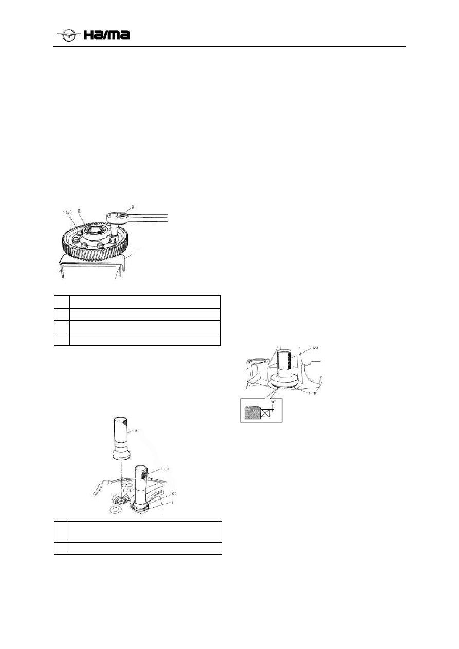
1)  Mount the input shaft’s oil seal and keep the 

spring side upward. During the mounting 
process, use special tool and hammer.   

Special tool(A):bearing erector6 


Intermediate shaft’s right bearing outer ring 

Input shaft oil seal   

2)  Use special tool and hammer to mount the 

intermediate shaft’s right bearing outer ring 
and intermediate shaft’s oil tray.   

Special tools (B): Mounting connection rod   

(C): Bearing outer ring erector 

Special tools (D):Seal ring erector 

3)  Use special tool and hammer to mount the 

differential’s right oil seal till it keeps even 
with the housing surface.   

Notice 

  Make differential oil seal’s spring side face 

inward 

Special tools (E): Oil seal erector1 

Differential gear oil seal’s mounting depth: 
“a”:1.0-1.5mm 

2.4.5 Left Box Body   

1)  Use strap hammer and special tool to mount 

the oil seal on the left side of differential till 
the height difference with the housing surface 
ranges between 1.0mm and 1.5mm.   

Notice 

  Make the oil seal’s spring side face inward   

Special tools(A):Oil seal erector2: differential oil 
seal’s mounting depth: “a”: 1.0-1.5mm 


2)  Use special tool and hammer to drive the 

intermediate shaft’s left bearing outer ring 
and intermediate shaft’s shim into left box 
body’s left bearing hole.   


Oil seal


1. Main reducer gear bolt 
2. Final reduction gear 
3. Torque wrench 
4. Soft bench clamp 

-------------------------------------------------------------------------------------------------------------------------------------------------------------


MF515L Transmission

 1H-16 


Attached Table 1: Special Tools 


Snap ring plier 

Dial gauge 

Magnet base 

Bearing outer ring 

erector 

Spring pin ejector 

(6.0mm) 

Bearing puller 

accessories 


Box splitter 

Bearing puller 

Oil seal    erector1

Bearing  

erector4 

Gear fixer 

Slide shaft 


Oil seal   

erector2 

Bearing erector1 

Bearing erector2

Bearing  

erector5 

Bearing ejector 

Bush ejector 


Bearing erector2 

Spring pin 

ejector(4.5mm) 

Oil seal ejector

Bearing erector6 

Bearing erector7 


Bearing erector3 

Mounting connection 

rod 

Seal ring erector


-------------------------------------------------------------------------------------------------------------------------------------------------------------


MF515L Transmission

 1H-17 


Attached Table 2: Reference List of MF515M01 Transmission Bolt Tightening Torques 

No. Name 

Qty 

Tightening 

torque(N·m) 

Remark 

Shift locking bolt assembly 

20~25  

2 Shift 

stop 

pin 

1  10~15  

Reverse shift fork bolt 

15~20  

Neutral signal sensor bolt 

7~10  

reverse gear shaft bolt 

18~28  

Release bearing mounting bolt 

7~10  

7 Assembling 

bolt 

14  18~28  

Reversing lamp switch assembly 

15~20  

Oil inlet plug 

12~18  

10 

Observation plug screw 

12~18  

11 Drain 

plug 

1  12~18  

12 Gearbox 

bolt 

4  10~15  

13 Lifting 

lug 

bolt 

10~15  

14 

Cable bracket bolt 

19~25  

15 

Oil delivery groove bolt 

7~10  

16 

Suspension connection bolt 

65~75  

17 Double-head 

bolt 

65~75  

18 Differential 

bolt 

80~100  

19 

Spring seat bolt 

7~10  


-------------------------------------------------------------------------------------------------------------------------------------------------------------


Gearshift Mechanism

 1J-1 


Chapter 9  Gearshift Mechanism   

Table of Contents 

Gearshift Mechanism ························································································1J-2 
Manual Gearshift Mechanism Dismantling/Mounting················································· 1J-2 


-------------------------------------------------------------------------------------------------------------------------------------------------------------


Gearshift Mechanism

 1J-2 


1. Gearshift Mechanism   

1.1 Manual Gearshift Mechanism 
Dismantling/Mounting 

1.  Firstly, dismantle the assistant instrument 

platform assembly; 

2.  Then remove them as illustrated shift 

mechanism, contrary installation and removal 
order.  

3.  After the mounting, confirm if the mechanism 

is fixed and can run stably.   


1  Manual gearshift lever assembly 
2 Gearshift 

handle 

3 Flange 

bolt 

4 Flat 

washer 

5 Cable 

assembly 


6 Flange 

nut 

Notice 

1.   Control the cable and connect it with 

the transmission correctly (no reverse mounting in 
gear selection and shift) 

2.  During the dismantling process, keep 

cautious and do not injure the cable buckle. After 
the assembly be sure to check whether the card slot 
into place.   

-------------------------------------------------------------------------------------------------------------------------------------------------------------


Content      ..     7      8      9