Haima S5 1.5T. A/C, Restraint System, Body Accessories, Electrical System. Manual - part 8


  Index      Haima     Haima S5 1.5T. A/C, Restraint System, Body Accessories, Electrical System. Service Manual


Search            copyright infringement  


Content      ..     6      7      8      9     ..


Haima S5 1.5T. A/C, Restraint System, Body Accessories, Electrical System. Manual - part 8


Electrical System 3D-16
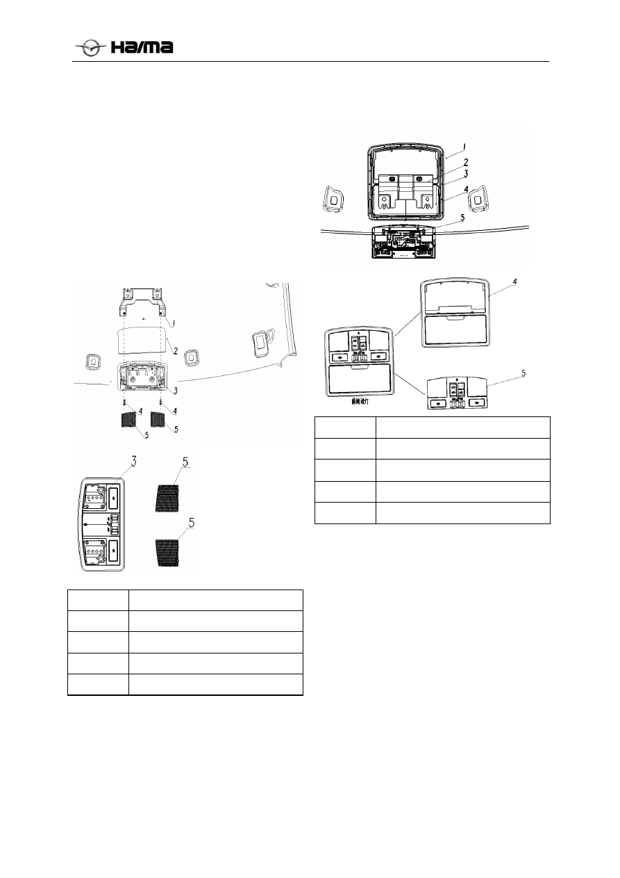


Interior Lamp 

Removal/Installation of Front Reading 


Lamp (low version) 

1.  Remove the negative cable of the battery. 

2.  The reading lamp shade lamp body upturned 

former interior lights out with a slotted 
screwdriver. 

3.    Use a Phillips screwdriver to two self-tapping 

screws on the lamp housing removed. 

4. Remove 

the 

connector. 

5.  Perform the installation in reverse order of the 

removal.  


1 Reading 

lamp 

bracket 

2 Roof 

body 

Low distribution front reading lamps

4 Self-tapping 

screws 

5 Reading 

lamp 

shade 

Removal/Installation of Front Reading 


Lamp (High version with glasses box) 

1.  Remove the negative cable of the battery. 

2.  The reading lamp shade lamp body upturned 

former interior lights out with a slotted 
screwdriver. 

4.  Remove the connector. To replace the wick. 

5.  Perform the installation in reverse order of the 

removal.  


1 Roof 

body 


2 Body 

bracket 

Reading lamp bracket  

Front reading lamp body 

Front reading lamp wick 

Note: When the production assembly, the first line 
under the reading lamp light body frame fitted with 
front reading lights on the ceiling, then along the 
ceiling to install the lamp body stuck in the body 
iron bracket. Then plug in the connectors, the 
reading lamp wick fasten the lamp body. 

Removal/Installation of Rear Interior 
Lamp  (low version) 

1.  Remove the negative cable of the battery. 

2.    Dome lamp shade after Alice out with a slotted 

screwdriver. 

3. Use a Phillips screwdriver to attach the two lock 

bolts removed. 

4. Remove the connectors. 

5. Replace the rear interior lamps. 

After the ceiling bracket is glued to the ceiling, 
with the ceiling supplied together, contrary 
installation and removal order. 

-------------------------------------------------------------------------------------------------------------------------------------------------------------


Electrical System 3D-17


1 Roof 

body 


Rear interior lamp bracket 

Rear interior lamp 

4 Bolt 

Rear interior lamp cover 

Removal/Installation of Rear Interior 
Lamp  (High version) 

1.  Remove the negative cable of the battery. 

2. After Alice the dome using a flathead 

screwdriver. 

3. Remove the connectors. 

4. Replace the rear interior lamps. 


1 Roof 

body 


Rear interior lamp  (High version) 

Removal/Installation of Rear Interior 


Lamp Bulb 

This interior lamp is of LED source, so please 
replace the lamp integrally if it is damaged. 

Trunk Lamp 

Removal/Installation of Trunk Lamp 

1.  Disconnect the negative cable of the battery. 

2.  Pry up the trunk lamp and remove it. 

3.  Remove the connector and remove the trunk 

lamp. 

4.  Perform the installation in reverse order of the 

removal. 


1


C-pillar trim trunk


2


Trunk lamp


Removal/Installation of Trunk Lamp 
Bulb 

This trunk lamp is of LED source, so please 
replace the lamp integrally if it is damaged. 

Courtesy Lamp  

Removal/Installation of Courtesy Lamp  

1.  Remove the negative cable of the battery. 

2.  Remove the front door trim plate body. 

3. Remove 

the 

connector. 

4.  Unscrew the back of the front door trim body 

lamps. 

5.  Perform the installation in reverse order of the 

removal. 


Courtesy lamp cover 

Front door trim plate body 

-------------------------------------------------------------------------------------------------------------------------------------------------------------


Electrical System 3D-18


2 Courtesy 

lamp 

Removal/Installation of Courtesy Lamp 
Bulb 

1.  Remove the courtesy lamp cover. 

2.  Replace the courtesy lamp bulb. 


Courtesy lamp cover 

2 Bulb 

(5W) 

3 Lamp 

socket 


Bulb Specification List : 

Bulb


Model

Voltages power


Front fog lamp


H3 12V 55W


Front position 
lamp


 12V 5W


Headlamp (low 
beam)


H1 12V 55W


Headlamp (high 
beam)


H1 12V 55W


Front turn signal 
lamp


 12V 

PY21W

Rear turn signal 
lamp


 12V 

PY21W

Brake lamp / rear
position lamp


 12V 

P21/5W

Reverse lamp


 12V 

W16W

Daytime running 
lamp


LED 12V  10W


Rear fog lamp


 12V 

P21W


High-mounted 
brake lamp


LED 12V  3W


Interior lamp


LED 12V  1W


Trunk lamp


LED 12V  1W


License plate 
lamp


LED 12V  1W


Wipers and Washers 

1. Wiper system 

The wiper system consists of the motor, the 
linkage and the wiper arm.  

Wiper system can be used when the ignition switch 
is turned to ON position. 

The wiper control lever is integrated in the 
combination switch, for controlling the wiper and 
the washer. Front wiper are 5 positions: MIST- 
Demisting ,OFF-stop, INT-intermittent (auto) 
wiping, HI-high speed wiping and O-low speed 
wiping. Rear wiper are 2 positions: OFF-stop,ON-
wiping. 

Push or pull the control lever to select the desired 
position.  

2. Washer 

system 

The washer system consists of the water reservoir, 
the motor, the injection nozzle and the water pipe.  

The washer reservoir is installed in the engine 
compartment. The washer motor installed on the 
water reservoir shall supply water via the water 
pipes to the nozzles installed on the engine hood. 
The washer and the wiper share the same control 
lever, which is integrated in the combination 

switch. Stalls were PULL- front spraying, 

 - 

rear spraying. 

Removal/Installation of Wiper Blade  

1.  Pull down the wiper blade via pushing the 

wiper blade clamp. 

2.  Perform the installation in reverse order of the 

removal. 


Figure 1: Schematic diagram of removing wiper 

Removal/Installation for Wiper Arm 

1.   Unplug the arm cover 1 wiper arm along the 

vertical direction; 

2.     Use a wrench to remove the nut 2; 

3.     Remove the front wiper wiper arm 3; 

-------------------------------------------------------------------------------------------------------------------------------------------------------------


Electrical System 3D-19


4.     Removing the wiper wiper 4 disassembly. 

5.  The installation is in reverse order of the 

removal. 

6.  Adjust the wiper arm and the wiper blade. 


Figure 2: schematic front wiper wiper arm 
disassembly


Figure 3: schematic rear wiper wiper arm 
disassembly


Installation instruction: 

Use a brush to clean the wiper arm connecting 
shaft prior to the installation.  

Adjusting the wiper arm and the wiper 
blade:  

1.   Operate the wiper motor to make the wiper 

stop at the start position. 

2. 

Adjust the wiper arm, as shown in the figure 
5 below.  


Figure 4: The wiper installation points 


Figure 5: The wiper installation initial position 


Removal/Installation of Front Wiper 
Motor 

1.  Disconnect the negative cable of the battery. 

2.  Remove the wiper arm and the wiper blade 

(Refer to the “Wiper Arm” and “Wiper Blade” 
sections). 

3.  Figure 6 schematic front grille surround 

demolition; 

4.  Figure 7 schematic Removing wiper motor 

assembly; 

4.1  Unplug the wiring harness plug 1; 

4.2  Removing illustration of three locking bolt 2. 

5.  Remove the wiper motor linkage assembly. 

6.  The installation is in reverse order of the 

removal. 


Figure 6: Schematic diagram of removing front 

grille surround 

End pressure in 
the second line   

2

1    

3    

1    

1    

2    

4    

3    

-------------------------------------------------------------------------------------------------------------------------------------------------------------


Electrical System 3D-20


Figure 7: Schematic diagram of removing front 

wiper motor 

Removal/Installation of Rear Wiper 
Motor 

1.  Disconnect the negative cable of the battery. 

2.  Remove the wiper arm and the wiper blade 

(Refer to the “Wiper Arm” and “Wiper Blade” 
sections). 

3.   Removing the diagram in Figure 8 a back door 

trim; 

4.   After the schematic in Figure 8 Removing the 

wiper motor assembly; 

4.1 Unplug the wiring harness plug; 

4.2 Remove the wiper motor linkage assembly. 

5.  The installation is in reverse order of the 

removal. 


Figure 8: Schematic diagram of removing wiper 

motor 


Figure 7: wiper motor 

Notice: The wiper motor and the linkage are fixed, 
so please don’t separate the motor from the wiper 
linkage.  

Removal/Installation of Washer Reservoir  

1.  Disconnect the negative cable of the battery. 

2.     Remove the front bumper 1; 

3.    Unplug the washing motor harness connector 

2 and washing motor 1 # washing line 3; 
 

4.    Remove the wash tank is fixed at four bolts 4 

to complete the demolition; 

5.     Remove the process with reference to FIG. 

6.  Perform the installation in reverse order of the 

removal. 


Figure 10: schematic view of the washing tank 

disassembly


Removal/Installation of Washer Motor 

1.  Disconnect the negative cable of the battery. 

2.  Remove the washer reservoir. Refer to the 

“Washer Reservoir” section. 

3.  Drain the washing liquid. 

2    

1

2

-------------------------------------------------------------------------------------------------------------------------------------------------------------


Electrical System 3D-21


4.  Remove the process Referring to Figure 11;  

5.  Perform the installation in reverse order of the 

removal. 


Figure 11: wash motor dismantling


Removal of Washer Nozzle  

1.  Remove the cowl grille assembly (windshield 

nozzle) / disassembly tail assembly (rear 
window nozzle); 

2.  Remove the washer pipe from the front 

washer nozzle. 

3.  According to the direction indicated in Figure 

12 pressed against the elastic force of the clip 
on the nozzle, the nozzle can be removed and 
then push up the nozzle. 


Figure 12: Schematic diagram of removing 

Windshield washer nozzles 

Installation of Washer Nozzle  

1.  Place the windshield washer hose and 

windshield washer nozzles connected; 

2.   The windscreen washer nozzle pressed into 

the mounting hole; 

3.    Adjust the windshield washer nozzles; 

4.  On the front grille surround / rear wing 

assembly is installed.


Cleaning the nozzle 

If nozzle clogging occurs, wash the tube removed, 
the nozzle outlet nozzle for tight, open wash motor 
nozzle recoil. If the blockage is serious, the 
available fine wire inserted in the front and rear 
washer nozzle and pull the cleaning nozzle, and 
then use the above method for cleaning. Note that 
not too sharp metal head.


Figure 13: Windshield washer nozzles 

Removal/Installation of Windshield 
Washer Pipe 

1.  Remove the front grille surround; 

2.  Disconnect the washer pipe from the washer. 

3.     Disconnect between washing lines; 

4.  Remove the washer pipe. 

5.  Perform the installation in reverse order of the 

removal. 


Figure 14: washing piping schematic view 

-------------------------------------------------------------------------------------------------------------------------------------------------------------


Electrical System 3D-22


Removal/Installation of Rear windscreen 
washer pipe 

1.    Remove the tail on the right carpet, D pillar 

trim panels and instrument panel and other 
components; 

2.    Disconnect the connection after the nozzle and 

pipe between; 

3.     Remove the washing lines; 

4.  Perform the installation in reverse order of the 

removal. 

Combination Instrument 

Removal/Installation of Combination 
Instrument 


1.  Disconnect the negative cable of the battery. 

2. Remove the central control panel 

(combination meter cover). (See the central 
control panel removal / installation). 

3.  Remove the combination instrument. 

● Use a screwdriver to remove the two screws 


● Unplug the instrument on the clamp ③ 

● Disconnect the connector ④ 

● Remove the combination meter ② 

4.  The installation is in reverse order of the 

removal. 

Speedometer 

1.  Apply the speed detector. 

2.  Adjust the tire pressure to the specified value. 

3.  When using the speed detector, please ensure 

the indication of the speedometer is within the 
following permissible range:  


Indication of Speed Detector

(Km/h)


Permissible Range 

(Km/h)


40


40-48


80


80-92


120


120-136


4.  If the speedometer pointer does not move or 

the indication exceeds the permissible range, 
check the ABS control module / ESP control 
module and relevant harness. If they are 
normal, replace the combination instrument. 

Tachometer 

1.  Apply the static speed tester.  

2.  Ensure the indication of the static speed tester 

is within the following permissible range: 


Indication of Speed Tester 

(rpm)

Permissible Range 

(rpm)


1,000


900-1,100


2,000


1850-2,150


3,000


2,850-3,150


4,000


3,850-4,150


5,000


4,850-5,150


6,000


5,800-6,200


3.  If the static speed tester pointer does not 

move or the indication exceeds the 
permissible range, check the engines peed 
signal and relevant harness. If they are normal, 
replace the combination instrument. 

-------------------------------------------------------------------------------------------------------------------------------------------------------------


Electrical System 3D-23


Combination Instrument 

The combination instrument, consisting of the speedometer, the tachometer, the odometer, 
the trip odometer, the coolant temperature sensor, the fuel level gauge, the trip computer 
(optional) and various indicator lamps, is used for providing various information about 
running.  


Name Icon 

Description 

Engine tachometer 


Indicating the engine speed, in unit of: x1000r/min. 

Coolant temperature 

gauge 


Indicating the engine temperature. The temperature is normal when its 
pointer is located in the middle. When it is located within the red zone, 
please stop the vehicle to let the engine cool down. 

Fuel level gauge 


Indicating the fuel tank level. When the fuel level is too low, the warning 
lamp comes on; when the pointer is approaching to C, add fuel as soon as 
possible. 

Trip computer 


The fuel consumption and the distance per charge 

Speedometer 


Indicating the instantaneous speed of the vehicle, in km/h. 

Odometer  

Indicating 

the 

total 

mileage and the trip mileage. 

Instrument adjustment 

lever 


It can be adopted to reset the trip mileage and adjust the instrument 
backlight. 

Left turn signal 

indicator lamp 


When the left turn signal lamps are turned on, this indicator lamp flickers 
at the same time. When the hazard warning lamp switch is pressed, both 
left and right turn signal lamps flicker. 

Right turn signal 

indicator lamp 


When the right turn signal lamps are turned on, this indicator lamp flickers 
at the same time. When the hazard warning lamp switch is pressed, both 
left and right turn signal lamps flicker. 

ABS system warning 

lamp 


Indicating the ABS system fault 

Parking brake 

warning lamp 


This lamp comes on: ① when the parking brake handle is applied or 
incompletely released; or ② when the brake fluid level is low; or ③ when 
the ABS warning lamp comes on, indicating there is EBD system fault. 

Burglar alarm lamp 

This lamp flickers to indicate the vehicle burglar system is operating. 

Front fog lamp 

indicator lamp 


This indicator lamp comes on when the front fog lamps are turned on. 

Rear fog lamp 

indicator lamp 


This indicator lamp comes on when the rear fog lamps are turned on. 

Fuel level warning 

lamp 


This warning lamp comes on when the fuel in the tank is nearly exhausted. 
Add fuel as soon as possible. 

Door open warning 

lamp 


This lamp comes on when any of the doors is open. 

Airbag warning lamp 


If this warning lamp comes on in engine operation, it is indicated there is 
fault in the airbag system. 

High beam indicator 

lamp 


This indicator lamp comes on when the high beams are turned on. 

Engine exhaust fault 

lamp 


If this warning lamp comes on in engine operation, it is indicated there is 
fault in the exhaust system. 

Engine fault lamp 


If this warning lamp comes on in engine operation, it is indicated there is 
engine fault. 

Oil pressure warning 

lamp 

  This warning lamp comes on indicating the low oil pressure. 

-------------------------------------------------------------------------------------------------------------------------------------------------------------


Electrical System 3D-24


Battery charging 

warning lamp 


This indicator lamp comes on when the battery cannot be normally 
charged. 

Coolant temperature 

warning indicator 


Indicating the engine temperature. When the coolant temperature warning 
lamp comes on, please stop the vehicle to let the engine cool down. 

ESP status indicator 

lamp 


With the ESP ON, this indicator lamp won’t come on if there is no ESP 
system fault; this indicator lamp comes on if there is any fault. 

ESP OFF indicator 

lamp 


This indicator lamp comes on when the ESP is off; it goes out after the ESP 
is turned on. 

Transmission fault 

indicator lamp 


This indicator lamp comes on when there is transmission fault. 

Small lamp signal 

indicator 


This indicator lamp comes on when the switch is turned to the small lamp 
signal. 

Seat belt unfastened 

warning lamp 


This warning lamp comes on when the seat belt is unfastened. 

EPS fault indicator 


When the electric power steering system failure, this lights. 

Cruise indicator 


When the cruise control system enters standby mode, the indicator is 
yellow; when the cruise control system into the cruise, the indicator is 
green. 

Start and stop lights 


The current can be started or stopped, the green indicator light; start-stop 
function is active, but the current state can not start and stop, yellow light; 
start-stop function is activated but currently there is a fault can not be 
started or stopped, the yellow light is flashing. 

Smart key fault 


PEPS and ESCL fault when this indicator is lit. 

Warning tone 

SA12-55-430/ 

SA22-55-430 


 (1) Small lamp ON warning 
With the key located at OFF position, when the small lamp is not turned off 
and the left front door is open, the buzzer alarms continuously. After the 
left front door is closed or the small lamp is turned off or the ignition key is 
turned on, the buzzing stops immediately. 
(2) Key-in-ignition warning 
With the key located at OFF position, the buzzer alarms continuously when 
the left front door is open. After the left front door is closed or the key is 
removed or the ignition key is turned on, the buzzing stops immediately. 
 (3) Seat belt unfastened warning 
When the ignition switch to ON file, the seat belt is not sitting, the sound of
the buzzer 3; if the speed exceeds 20km / h, seat belt on, the buzzer gap 
prompts. 
(4) Door open warning 
When any of the doors is open, this indicator lamp comes on; when any of 
the doors is open at the vehicle running speed over 10km/h, this indicator 
lamp comes on with buzzing. After the door is closed, the warning is 
cleared and the indicator lamp goes out. 
(5) Turn signal tone 
When the combination switch to turn left or right, the hazard warning 
switch is turned on, the left and right turn indicator lights, notice 
accompanied by voice prompts, lights flicker frequency and consistent 
frequency. Controlled by the BCM. 
(6) Hand brake unreleased warning tone 
With ignition key located at ON position and the hand brake unreleased, 
the buzzer alarms when the vehicle speed is over 0km/h. After the hand 
brake is released or the vehicle speed is 0, the buzzing stops immediately. 
(7) Speed alarm 
 When the actual speed is greater than the set speed, began to alarm buzzer, 
LCD screen pop-up alarm. 

-------------------------------------------------------------------------------------------------------------------------------------------------------------


Electrical System 3D-25


Priority: the ignition switch in the ON file: (6)> (4)> (3)> (7)> (5) 

When the ignition switch is in OFF position, (5)> (2)> (1) 

Warning tone 

SA22-55-430/ 


(1) Small lamp ON warning 
With the key located at OFF position, when the small lamp is not turned off 
and the left front door is open, the buzzer alarms continuously. After the 
left front door is closed or the small lamp is turned off or the ignition key is 
turned on, the buzzing stops immediately. 
(2) Key-in-ignition warning 
With the key located at OFF position, the buzzer alarms continuously when 
the left front door is open. After the left front door is closed or the key is 
removed or the ignition key is turned on, the buzzing stops immediately. 
 (3) Seat belt unfastened warning 
When the ignition switch to ON file, the seat belt is not sitting, the sound of
the buzzer 3; if the speed exceeds 20km / h, seat belt on, the buzzer gap 
prompts. 
(4) Door open warning 
When any of the doors is open, this indicator lamp comes on; when any of 
the doors is open at the vehicle running speed over 10km/h, this indicator 
lamp comes on with buzzing. After the door is closed, the warning is 
cleared and the indicator lamp goes out. 
(5) Turn signal tone 
When the combination switch to turn left or right, the hazard warning 
switch is turned on, the left and right turn indicator lights, notice 
accompanied by voice prompts, lights flicker frequency and consistent 
frequency. Controlled by the BCM. 
(6) Hand brake unreleased warning tone 
With ignition key located at ON position and the hand brake unreleased, 
the buzzer alarms when the vehicle speed is over 0km/h. After the hand 
brake is released or the vehicle speed is 0, the buzzing stops immediately. 
(7) Speed alarm 
 When the actual speed is greater than the set speed, began to alarm buzzer, 
LCD screen pop-up alarm. 
(8) When ON file, did not find the key to the door shut, requiring indicator 
light, with buzzer alarm rang four under after the alarm sound stops. 
(Optional) 
Priority: the ignition switch in the ON file: (6)> (4)> (3)> (7)> (5) 
              When the ignition switch is in OFF position, (5)> (2)> (1) 


-------------------------------------------------------------------------------------------------------------------------------------------------------------


Electrical System 3D-26


Removal/Installation of Audio Assembly 

Audio system components  

N
o. 

Part No. 

Part Name 

Picture 

Applicable 
vehicles 

SA12-66-
9R2 

Audio host 


Standard(1.6L)

SA32-66-
9R2 

Audio host 


Elite

1.5T+6MT) 

Elite

1.5T+CVT) 

SA22-66-
9R2 

Audio host 


1.6L Comfort 、
Deluxe、Noble  ;
1.5T+6MT 
Noble

1.5T+CVT 
Deluxe、Noble 

SA42-66-
9R2 


1.6L Elite

1.5T+6MT 
Deluxe; 

-------------------------------------------------------------------------------------------------------------------------------------------------------------


Electrical System 3D-27


SA12-66-
9R1 

Audio Display 


1.6L Elite

Comfort

Deluxe 、 Noble ;
1.5T+6MT 
Deluxe 、 Noble ;
1.5T+CVT 
Deluxe、Noble 

SA12-66-
452 

USB Cable 


Whole system 
comes standard 

SA12-66-
9R6 

SD Card 


1.6L Elite

Comfort

Deluxe 、 Noble ;
1.5T+6MT 
Deluxe 、 Noble ;
1.5T+CVT 
Deluxe、Noble 

SA12-66-
964 

Small tweeters 


1.6L Elite

Comfort

Deluxe 、 Noble ;
1.5T+6MT 
Deluxe 、 Noble ;
1.5T+CVT 
Deluxe、Noble 

SA12-66-
963 

Rear door speaker 


Whole system 
comes standard 

10 

SA12-99-
962 

Front door speaker 


Whole system 
comes standard 

-------------------------------------------------------------------------------------------------------------------------------------------------------------


Electrical System 3D-28


11 

SA12-66-
8A1 

Rod antenna 
assembly 


Standard ( 1.6L )
Elite

1.5T+6MT) 

Elite

1.5T+CVT) 

12 

SA12-66-
942 

Feeder assembly 
(short) 


Standard ( 1.6L )
Elite

1.5T+6MT) 

Elite

1.5T+CVT) 

13 

SA12-66-
941 

Feeder assembly 
(long) 


Standard ( 1.6L )
Elite

1.5T+6MT) 

Elite

1.5T+CVT) 

14 

SA12-66-
931 

Shark fin antenna 
combination 


1.6L Elite

Comfort

Deluxe 、 Noble ;
1.5T+6MT 
Deluxe 、 Noble ;
1.5T+CVT 
Deluxe、Noble 

15 

SA12-66-
946 

GPS feeder (short) 


1.6L Elite

Comfort

Deluxe 、 Noble ;
1.5T+6MT 
Deluxe 、 Noble ;
1.5T+CVT 
Deluxe、Noble 

16 

SA12-66-
945 

GPS feeder (long) 


1.6L Elite

Comfort

Deluxe 、 Noble ;
1.5T+6MT 
Deluxe 、 Noble ;
1.5T+CVT 
Deluxe、Noble 


Diagnostic Information and Procedure of Audio system 


-------------------------------------------------------------------------------------------------------------------------------------------------------------


Electrical System 3D-29


Fault Possible 

Cause 

Troubleshooting 

Method

The unit's power or car battery fuse. 

Replacing the correct 
type of fuse. 

Can not boot 

The supply voltage exceeds the rated operating 
range, the system automatically protected. 

Car battery voltage and 
then boot. 

Poor grounding  

Replace or repair the 
ground wire. 

Radio fault 

Replace the radio. 

Radio failure 

Blown fuse 

Replace the fuse. 

Obstacles existed in the CD bin 

Take out the obstacles/ 

Abnormal operation 
of the CD player  

CD player movement fault 

Replace the CD player. 

FM failure, with 
normal AM and 
playback 

Radio fault 

Replace the radio. 

Imperfectly received signal (use a test antenna to 
test the AM reception) 

Replace the radio. 

AM failure, with 
normal FM and 
playback 

Well received signal (use a test antenna to test the 
AM reception) 

Replace the antenna and 
feeder. 

Audio output cable connection errors. 

Refer to "System 
Connection General 
Plan" audio input cable 
is connected properly. 

The host or the connected device or lower the 
volume muted. 

Host or off mute or 
increase the volume of 
the connected device. 

Speaker failures. 

Repair or replace 
speaker. 

Sound field balance setting deviation is too large. 

Adjust the balance of the 
sound field to 
intermediate values. 

No sound output or 
sound output is small 

Speaker cables come into contact with the body 
or the ground. 

Connecting the speakers 
with insulated wire and 
cable wrap with plastic 
insulation bare spots. 

Use of poor quality discs. 

The use of legitimate 
discs. 

Does not match the speaker power with this 
machine. 

Replace the right 
speaker. 

Speaker to be shared between the connecting 
wires. 

The speaker output 
terminals are connected 
to each speaker 
terminals. 

Poor sound quality or 
sound distortion 

Online access to the vehicle speaker screws. 

Check the speaker 
connections. 

A door speaker damaged or loosened 

Check the speaker and 
its installation. 

The circuit between the door speaker and the 
radio player open or short 

Repair the circuit. 

Door speaker 
distortion or failure  

Poor contact between the door speaker connector 
and the radio player connector 

Plug the connector 
securely.  

-------------------------------------------------------------------------------------------------------------------------------------------------------------


Electrical System 3D-30


Door speaker fault 

Replace the speaker. 

Radio fault 

Replace the radio. 

 The tweeter damaged or loosened 

Check the speaker and 
its installation. 

The circuit between the tweeter and the radio 
player open or short 

Repair the circuit. 

Poor contact between the tweeter connector and 
the radio player connector 

Plug the connector 
securely.  

Tweeter fault 

Replace the speaker. 

Tweeter distortion or 
failure 

Radio fault 

Replace the radio. 

Automatic car antenna is not fully extended. 

According to the 
"System Connection 
General Plan" automatic 
antenna line is properly 
connected. 

 Radio poor results 

Radio antenna is not properly connected. 

Accordance with the 
"General Plan System 
Connection" radio 
antenna is connected 
properly. 

 Unable to put the disc 

Dish within existing warehouse 

Pop the disc 
compartment, and then 
insert the disc 

Scratched discs can not be read 

Good disc replacement 

The disc is dirty or wet 

Clean the disc 

Add this disc format is not supported 

Replacing native support 
disc format 

Discs can not be played 

CD positive and negative reversed 

The disc label-side up 
into the cabin 

Navigation data card is not inserted. 

Insert the supplied 
navigation data card. 

Unable to enter the 
navigation system 

Navigation data card is damaged. 

Contact 4S store 
customer service 
personnel to solve. 

The environment in which the machine can not be 
good reception signal. 

Ensure that the machine 
is not in shielded or 
enclosed space. 

GPS antenna is not connected or loose. 

According to the 
"System Connection 
General Plan" GPS 
antenna is connected 
properly. 

When turned on, the
navigation system can 
not locate or often lose
positioning information 

Software accidental failures. 

Restart the machine. 

Not retrieve destination 

Retrieving land belongs locale error. 

The area belongs to the 
destination area. 


-------------------------------------------------------------------------------------------------------------------------------------------------------------


Electrical System 3D-31


Maintenance Instruction 

On-vehicle Maintenance 
Removal Procedure of 
Audio-CD Player  


1.  Disconnect the negative cable of the battery.  

2.  Remove the center of the vent panel (see the 

central control panel removal / installation). 

3.     Remove the headunit. 

.         


● Use a screwdriver to remove the four   screws ①; 

● The CD host pulled up ②; 

● Unplug the wiring harness connector ②; 

● Unplug the feeder assembly (short) connector ③; 

● Disconnect the USB cable connector ④; 

● Install the reverse order of removal order. 

Removal Instruction 

1.  Please handle gently in removal to protect the 

audio surface and screen from being damaged. 

2.  When removing the connector, press the clip 

at first and then pull it out. Don’t pull it 
directly by force; or else the connector may 
be damaged. 

3.  Remove the audio and keep it properly.  


Assembly Method 

Insert all connectors (except for the antenna, an 
clear “click” sound can be heard when the 
connector is installed in place). 

Installation Procedure 

In contrast with the mounting process. 

Before installing the audio into the instrument 
panel, check the audio for normal operation at first 
(connect all connectors and check whether the 
audio can be turned on and operate normally). 

1.  Connect the connector on the back of the audio 

panel. Press the audio panel to ensure uniform 
clearance around three sides (the clearance 
between it and the instrument panel or A/C 
controller should be 1mm); push it backward.  

2.  Push the audio host into the mounting hole and 

use a phillips screwdriver to install 4 self-
tapping screws. 

3.  Replace the central control panel (combination 

meter cover). 

Assembly tip:  

During assembly, please ensure the clearance 
between the audio panel and the instrument panel 
is uniform. 

Removal Procedure of Audio-DVD Player  


1.  Disconnect the negative cable of the battery.  

2.  Remove the central control panel (see the 

central control panel removal / installation). 

3.     Remove the headunit. 

● Use a screwdriver to remove the four   screws ①; 

-------------------------------------------------------------------------------------------------------------------------------------------------------------


Content      ..     6      7      8      9     ..