Lancia VOYAGER. Service Manual - part 8
 

  Index      Manuals     Lancia VOYAGER. Service Manual


Search            copyright infringement  


Content      ..     6      7      8      9     ..


Lancia VOYAGER. Service Manual - part 8


To Unfold Third Row Seats

1. Pull up on the assist strap to lift
the seat out of the storage bin and
push the seat forward until the an-
chors latch.

2. Pull release strap marked “2” to
unlock the recliner.

3. Pulling strap “4” releases the seat-
back to return to its full upright posi-
tion.

4. Raise the head restraint to its up-
right position.

WARNING!

• In a collision, you or others in

your vehicle could be injured if
seats are not properly latched to
their floor attachments. Always
be sure the seats are fully latched.

• Sitting in a seat with the head

restraint in its lowered position
could result in serious injury or
death in a collision. Always make
sure the head restraints are in
their upright positions when the
seat is to be occupied.

Tailgate Mode

1. Pull release strap “3”, then pull
release strap “4” to rotate the entire
seat rearward.

2. To restore the seat to its upright
position, lift up on the seatback and
push forward until the anchors latch.

WARNING!

To avoid serious injury or death,
never operate the vehicle with oc-
cupants in the third row seat while
in the tailgate mode.

PLASTIC GROCERY BAG
RETAINER HOOKS

Retainer hooks which will hold plastic
grocery bag handles are built into the
seatbacks of all rear seats and some
front seats. The floor supports the
partial weight of the bagged goods.

DRIVER MEMORY SEAT
(for versions/markets,
where provided)

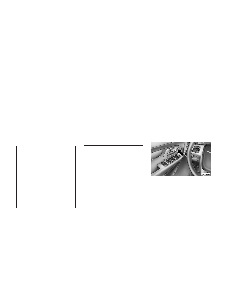
The Memory Buttons 1 and 2 on the
driver's door panel can be pro-
grammed to recall the driver's seat,
driver's outside mirror, adjustable
brake and accelerator pedals, and ra-
dio station preset settings. Your Re-
mote Keyless Entry (RKE) transmit-
ters can also be programmed to recall
the same positions when the UN-
LOCK button is pressed.

Your vehicle may have been delivered
with two RKE transmitters. Only one
RKE transmitter can be linked to each
of the memory positions.

Driver Memory Switch

125

-------------------------------------------------------------------------------------------------------------------------------------------------------------

SETTING MEMORY
POSITIONS AND LINKING
RKE TRANSMITTER TO
MEMORY

NOTE: Each time the SET (S) but-
ton and a numbered button (1 or 2)
is pressed, you erase the memory
settings for that button and store a
new one.

1. Insert the ignition key and turn the
ignition switch to the ON position.

2. Press the driver door MEMORY
button number 1 if you are setting the
memory for driver 1, or button num-
ber 2 if you are setting the memory for
driver 2. The system will recall any
stored settings. Wait for the system to
complete the memory recall before
continuing to Step 3.

3. Adjust the driver's seat, recliner,
and driver's side-view mirror to the
desired positions.

4. Adjust the brake and accelerator
pedals to the desired positions.

5. Turn on the radio and set the radio
station presets (up to 10 AM and 10
FM stations can be set).

6. Turn the ignition switch to the
OFF position and remove the key.

7. Press and release the SET (S) but-
ton located on the driver's door.

8. Within five seconds, press and re-
lease MEMORY button 1 or 2 on the
driver's door. The next step must be
performed within 5 seconds if you
desire to also use a RKE transmitter to
recall memory positions.

9. Select

“Remote

Linked

to

Memory” in the Electronic Vehicle In-
formation Center (EVIC) and enter
“Yes”. Refer to “Electronic Vehicle In-
formation Center (EVIC)/Customer-
Programmable Features” in “Under-
standing Your Instrument Panel” for
further information.

10. Press and release the LOCK but-
ton on one of the RKE transmitters.

11. Insert the ignition key and turn
the ignition switch to the ON position.

12. Repeat the above steps to set the
next Memory position using the other
numbered Memory button or to link
another RKE transmitter to memory.

Memory Position Recall

NOTE: The vehicle must be in
PARK to recall memory positions.
If a recall is attempted when the
vehicle is not in PARK, a message
will be displayed in the EVIC.

To recall the memory settings for
driver one, press MEMORY button 1
on the driver's door or the UNLOCK
button on the RKE transmitter linked
to memory position 1.

To recall the memory setting for
driver two, press MEMORY button 2
on the driver's door or the UNLOCK
button on the RKE transmitter linked
to Memory Position 2.

A recall can be cancelled by pressing
any of the MEMORY buttons on the
driver's door during a recall (S, 1, or
2). When a recall is cancelled, the
driver's seat, outside mirrors, and the

126

-------------------------------------------------------------------------------------------------------------------------------------------------------------

pedals stop moving. A delay of one
second will occur before another re-
call can be selected.

To Disable RKE Transmitter
Linked To Memory

1. Turn the ignition switch to the
OFF position and remove the key.

2. Press and release MEMORY but-
ton 1. The system will recall any
memory settings stored in position 1.
Wait for the system to complete the
memory recall before continuing to
Step 3.

3. Press and release the memory SET
(S) button located on the driver's
door.

4. Within five seconds, press and re-
lease the UNLOCK button on the
RKE transmitter.

To disable another RKE transmitter
linked to either Memory Position, re-
peat Steps 1 to 5 for each RKE trans-
mitter.

NOTE: Once

programmed,

all

RKE

transmitters

linked

to

memory can be easily enabled or

disabled at one time. Refer to
“Electronic Vehicle Information
Center

(EVIC)/Customer-

Programmable Features" in “Un-
derstanding

Your

Instrument

Panel” for further information.

EASY ENTRY/EXIT SEAT
(Available With Memory
Seat Only)

This

feature

provides

automatic

driver seat positioning to enhance
driver mobility when entering and ex-
iting the vehicle.

The distance the driver seat moves
depends on where you have the driver
seat positioned when you remove the
key from the ignition switch.

• When you remove the key from the

ignition switch, the driver seat will
move about 60 mm rearward if the
driver seat position is greater than
or equal to 68 mm forward of the
rear stop. The seat will return to its
previously set position when you
insert the key into the ignition
switch and turn it out of the LOCK
position.

• When you remove the key from the

ignition switch the driver seat will
move to a position 8 mm forward of
the rear stop if the driver seat posi-
tion is between 23 – 68 mm forward
of the rear stop. The seat will return
to its previously set position when
you insert the key into the ignition
switch and turn it out of the LOCK
position.

• The Easy Entry/Easy Exit feature

is disabled when the driver seat po-
sition is less than 28 mm forward of
the rear stop. At this position, there
is no benefit to the driver by moving
the seat for Easy Exit or Easy En-
try.

Each stored memory setting will have
an associated Easy Entry and Easy
Exit Position.

NOTE: The Easy Entry/Easy Exit
feature can be enabled or disabled
through the programmable fea-
tures in the Electronic Vehicle In-
formation Center (EVIC). If your
vehicle is not equipped with an
EVIC,

your

dealership

can

activate/deactivate this feature for

127

-------------------------------------------------------------------------------------------------------------------------------------------------------------

you. For details, refer to “Elec-
tronic Vehicle Information Center
(EVIC)/Customer-Programmable
Features” in “Understanding Your
Instrument Panel” for further in-
formation.

TO OPEN AND CLOSE
THE HOOD

To open the hood, two latches must be
released.

1. Pull the hood release lever located
on the instrument panel, below the
steering column.

2. Move to the front of the vehicle
and look inside the center of the hood
opening. Locate, then push the safety
catch lever downward while raising
the hood at the same time.

Use the hood prop rod to secure the
hood in the open position.

CAUTION!

To prevent possible damage, do not
slam the hood to close it. Lower the
hood until it is open approximately
30 cm and then drop it. This should
secure both latches. Never drive
your vehicle unless the hood is fully
closed, with both latches engaged.

WARNING!

Be sure the hood is fully latched
before driving your vehicle. If the
hood is not fully latched, it could
open when the vehicle is in motion
and block your vision. Failure to
follow this warning could result in
serious injury or death.

LIGHTS

All of the lights, except the Hazard
Warning lights, headlight high beams
and flash-to-pass, are controlled by
switches to the left of the steering
column on the instrument panel.

Hood Release Lever

Safety Lever Location

Headlight Switch With Halo Control

Assembly

128

-------------------------------------------------------------------------------------------------------------------------------------------------------------

INTERIOR LIGHTING

Interior lights are turned on when a
door or liftgate is opened, the Remote
Keyless Entry (RKE) transmitter is
activated, or when the dimmer con-
trol is moved to the extreme top.

The interior lights will automatically
turn off in approximately 10 minutes
for the first activation and 90 seconds
every activation thereafter until the
engine is started, if one of the follow-
ing occur:

1. A door, sliding door or the liftgate
is left open

2. Any overhead reading light is left
on

NOTE: The key must be out of the
ignition switch or the ignition
switch must be in the OFF position
for this feature to operate.

Halo Lights (for versions/markets,
where provided)

Halo lights are strategically placed
soft lighting that help to illuminate

specific areas to aid the occupants in
locating specific features while driv-
ing at night.

The Halo control switch is located to
the right of the dimmer switch.

To activate the Halo lights,
rotate the Halo switch con-
trol upward or downward
to increase or decrease the

lighting.

PARKING LIGHTS

Turn the headlight switch
knob to the first detent to turn

the parking lights on. This also turns
on all instrument panel lighting.

HEADLIGHTS

Turn the headlight switch
knob to the second detent to
turn the headlights and
parking lights on. This also

turns on all instrument panel lighting.

To change the brightness of the in-
strument panel lights, rotate the dim-
mer control up or down.

AUTOMATIC HEADLIGHTS
(for versions/markets,
where provided)

This system automatically turns your
headlights on or off based on ambient
light levels. To turn the system on,
turn the headlight switch to the ex-
treme

counterclockwise

position

aligning the indicator with AUTO on
the headlight switch. When the sys-
tem is on, the Headlight Time Delay
feature is also on. This means your
headlights will stay on for up to 90
seconds after you turn the ignition
switch OFF. To turn the Automatic
System off, turn the headlight switch
clockwise to the O (Off) position.

Halo Control Switch

129

-------------------------------------------------------------------------------------------------------------------------------------------------------------

NOTE: The engine must be run-
ning before the headlights will
come on in the Automatic mode.

HEADLIGHTS ON WITH
WIPERS (for versions/
markets, where provided)

When your headlights are in the Au-
tomatic mode and the engine is run-
ning, the headlights will automati-
cally turn on when the wiper system is
also turned on. In addition, the head-
lights will turn off when the wipers are
turned off if they were turned on by
this feature. Headlights on when
windshield wipers are on may be
found on vehicles equipped with an
automatic headlight system. Refer to
“Electronic Vehicle Information Cen-
ter (EVIC)/Customer-Programmable
Features” in “Understanding Your In-
strument Panel” for further informa-
tion.

HEADLIGHT DELAY (for
versions/markets, where
provided)

This feature provides the safety of
headlight illumination for up to
90 seconds after exiting your vehicle.

To activate the delay feature, turn OFF
the ignition switch while the headlights
are still on. Then turn off the head-
lights within 45 seconds. The 90 sec-
ond delay interval begins when head-
light switch is turned off. If the
headlights or parking lights are turned
back on or the ignition switch is turned
ON, the delay will be cancelled.

When exiting the vehicle the driver
can choose to have the headlights re-
main on for 30, 60, or 90 seconds or
not remain on. To change the timer
setting, see your authorized dealer.

The headlight delay time is program-
mable on vehicles equipped with an
EVIC. Refer to “Electronic Vehicle In-
formation Center (EVIC)/Customer-
Programmable Features” in “Under-
standing Your Instrument Panel” for
further information.

If the headlights are turned off before
the ignition, they will turn off in the
normal manner.

NOTE: The headlights must be
turned off within 45 seconds of
turning the ignition OFF to activate
this feature.

FRONT AND REAR FOG
LIGHTS (for versions/
markets, where provided)

The front and rear fog light switch is
built into the headlight switch.

The front and rear fog lights
may be operated as desired
when visibility is poor due to

fog. The fog lights will activate in the
following order: Press the headlight
switch once and the front fog lights

Fog Light Switch

130

-------------------------------------------------------------------------------------------------------------------------------------------------------------

come on. Press the switch a second
time and the rear fog lights will come
on (front fog lights stay on). Press the
switch a third time and the rear fog
lights turn off (front fog stays on).
Press the switch a fourth times and
the front fog turns off. For vehicles
without front fog, rear fog will acti-
vate on the first press.

An indicator light in the instrument
cluster illuminates when the fog lights
are turned on.

NOTE: The headlight switch must
be in parking lights or headlights
position to activate the front and
rear fog lamps.

BATTERY PROTECTION

This feature provides battery protec-
tion to avoid wearing down the bat-
tery if the headlights, parking lights,
or front fog lights are left on for ex-
tended periods of time when the igni-
tion switch is in the LOCK position.
After eight minutes of the ignition
switch being in the LOCK position
and the headlight switch in any posi-
tion other than OFF or AUTO, the

lights will turn off automatically until
the next cycle of the ignition switch or
headlight switch.

The battery protection feature will be
disabled if the ignition switch is
turned to any other position other
than LOCK during the eight minute
delay.

MULTIFUNCTION LEVER

The multifunction lever is located on
the left side of the steering column.

The multifunction lever controls the:

• Turn Signals

• Headlight Beams Low/High

• Flash-To-Pass (Optical Horn)

• Front and Rear Wipers — Washer

Functions

TURN SIGNALS

Move the multifunction lever up or
down and the arrows on each side of
the instrument cluster flash to show
proper operation of the front and rear
turn signal lights.

NOTE: If either light remains on
and does not flash, or there is a
very fast flash rate, check for a
defective outside light bulb. If an
indicator fails to light when the
lever is moved, it would suggest
that the indicator bulb is defective.

Turn Signal Warning

If the vehicle electronics sense that the
vehicle has traveled at over 30 km/h
for approximately 1.6 km with the
turn signals on, a chime will sound to
alert the driver.

HIGH/LOW BEAM SWITCH

When the headlights are turned on,
pushing the multifunction lever to-
ward the instrument panel will switch

Multifunction Lever

131

-------------------------------------------------------------------------------------------------------------------------------------------------------------

from low beams to high beams. Pull-
ing back to the neutral position re-
turns the headlights to the low beam
operation.

FLASH-TO-PASS

You can signal another vehicle with
your headlights by lightly pulling the
multifunction lever toward you. This
will turn on the high beam headlights
until the lever is released.

AUTOMATIC HIGH BEAM
(for versions/markets,
where provided)

The Automatic High Beam system
provides increased forward lighting at
night by automating high beam con-
trol through the use of a digital cam-
era mounted on the inside rearview
mirror. This camera detects vehicle
specific

light

and

automatically

switches from high beams to low
beams until the approaching vehicle
is out of view.

NOTE: Broken, muddy or ob-
structed headlights and taillights
of vehicles in the field of view will

cause headlights to remain on lon-
ger (closer to the vehicle). Also,
dirt, film and other obstructions
on the windshield or camera lens
will cause the system to function
improperly.

To Activate

1. Select “Automatic High Beams —
ON” through the EVIC. Refer to
“Electronic Vehicle Information Cen-
ter (EVIC)/Customer-Programmable
Features” in “Understanding Your In-
strument Panel” for further informa-
tion.

2. Rotate the headlight switch coun-
terclockwise to the AUTO (A) posi-
tion.

3. Push the multifunction lever away
from you to switch the headlights to
the high beam position. Refer to
“Multifunction Lever” in this section
for further information.

NOTE: This system will not acti-
vate until the vehicle is at, or
above, 40 km/h.

HEADLIGHT LEVELING
SYSTEM (for versions/
markets, where provided)

Your

vehicle

may

be

equipped with a headlight
leveling system. This sys-
tem allows the driver to

maintain proper headlight beam posi-
tion with the road surface regardless
of vehicle load. The control switch is
located on the instrument panel next
to the dimmer control.

To operate, rotate the control switch
until the appropriate number, which
corresponds to the load listed on the
chart, aligns with the indicator line on
the switch.

0

Driver only, or driver and
front passenger.

1

Driver, plus an evenly distrib-
uted load in the luggage com-

partment. The total weight of

the driver and load does not

exceed the maximum load

capacity of the vehicle.

132

-------------------------------------------------------------------------------------------------------------------------------------------------------------

2

All seating positions occupied,
plus an evenly distributed
load in the luggage compart-
ment. The total weight of pas-
sengers and load does not ex-
ceed the maximum load
capacity of the vehicle.

Calculations based on a passenger

weight of 75 kg.

WINDSHIELD WIPERS
AND WASHERS

The wipers and washers are operated
by a switch within the multifunction
lever. Rotate the end of the multifunc-
tion lever to select the desired wiper
speed.

NOTE: Always

remove

any

buildup of snow that prevents the
windshield wiper blades from re-
turning to the off position. If the
windshield wiper switch is turned
off and the blades cannot return to
the off position, damage to the
wiper motor may occur.

WARNING!

Sudden loss of visibility through
the windshield could lead to a col-
lision. You might not see other ve-
hicles or other obstacles. To avoid
sudden icing of the windshield dur-
ing freezing weather, warm the
windshield with the defroster be-
fore and during windshield washer
use.

MIST, FRONT WIPER AND
WASHER

Use the Mist feature when weather
conditions make occasional usage of
the wipers necessary.

Press the end of the multifunction lever
inward (toward the steering column) to
the first detent and release for a single

wiping cycle. To use the Washer, push
on the end of the lever to the second
detent and hold while spray is desired.
If the lever is pushed while on the in-
termittent setting, the wipers will turn
on and operate for several wipe cycles
after the lever is released, and then
resume the intermittent interval previ-
ously selected. If the lever is pushed
while the wipers are in the off position,
the wipers will operate several wipe
cycles, then turn off.

INTERMITTENT, LOW AND
HIGH SPEED WIPERS

Rotate the end of the lever to one of
the first five detent positions for inter-
mittent wiper operation, the sixth de-
tent for low wiper operation and the
seventh detent for high wiper opera-
tion.

Use one of the five intermittent wiper
settings when weather conditions
make a single wiping cycle, with a
variable delay between cycles, desir-
able.

At

driving

speeds

above

16 km/h, the delay can be regulated
from a maximum of approximately

Washer And Wiper Controls

133

-------------------------------------------------------------------------------------------------------------------------------------------------------------

18 second between cycles (first de-
tent), to a cycle every one second
(fifth detent).

NOTE: If the vehicle is moving
less than 16 km/h, delay times will
be doubled.

REAR WIPER AND
WASHER

Rotating the rotary ring to the first
detent activates the rear intermittent
wipers. To activate the washers, rotate
the rotary ring fully forward and the
washers will spray until the ring is
released, and then resume the inter-
mittent interval.

NOTE: Rear

window

wipers

function in the intermittent wiper
speed only.

WARNING!

Sudden loss of visibility through
the windshield could lead to a col-
lision. You might not see other ve-
hicles or other obstacles. To avoid
sudden icing of the windshield dur-
ing freezing weather, warm the
windshield with defroster before
and during windshield washer use.

RAIN SENSING WIPERS
(for versions/markets,
where provided)

This feature senses moisture on the
windshield and automatically acti-
vates the wipers for the driver. This
feature is especially useful for road
splash or overspray from the wind-
shield washers of the vehicle ahead.
Rotate the end of the multifunction
lever to one of the five intermittent
wiper sensitivity settings to activate
this feature.

The sensitivity of the system is adjust-
able from the multifunction lever.
Wiper sensitivity position 3 has been
calibrated for best overall wiping sen-
sitivity. If the operator desires more

wiping sensitivity, they may select
sensitivity positions 4 or 5. If the op-
erator desires less wiping sensitivity,
they may select sensitivity positions 2
or 1. Place the multifunction lever in
the OFF position when not using the
system.

NOTE:

• The Rain Sensing feature will

not operate when the wiper
speed is in the low or high posi-
tion.

• The Rain Sensing feature may

not function properly when ice
or dried saltwater is present on
the windshield.

• Use of products containing wax

or silicone may reduce rain sen-
sor performance.

• The Rain Sensing feature can be

turned on and off through the
EVIC

(for

versions/markets,

where provided). Refer to “Elec-
tronic Vehicle Information Cen-
ter

(EVIC)/Personal

Settings

134

-------------------------------------------------------------------------------------------------------------------------------------------------------------

(Customer-Programmable Fea-
tures)” in “Understanding Your
Instrument Panel” for further
information.

The Rain Sensing system has protec-
tive features for the wiper blades and
arms. It will not operate under the
following conditions:

• Low Temperature Wipe Inhibit

— The Rain Sensing feature will
not operate when the ignition is
first switched ON, and the vehicle is
stationary, and the outside tem-
perature is below 0°C, unless the
wiper control on the multifunction
lever is moved, or the vehicle speed
becomes greater than 0 km/h, or
the outside temperature rises above
freezing.

• Neutral Wipe Inhibit — The Rain

Sensing feature will not operate
when the ignition is ON, and the
transmission shift lever is in the
NEUTRAL position, and the ve-
hicle speed is less than 8 km/h,

unless the wiper control on the mul-
tifunction lever is moved or the
shift lever is moved out of the NEU-
TRAL position.

TILT/TELESCOPING
STEERING COLUMN

This feature allows you to tilt the
steering column upward or down-
ward. It also allows you to lengthen or
shorten the steering column. The tilt/
telescoping lever is located below the
steering wheel at the end of the steer-
ing column.

To unlock the steering column, push
the lever downward (toward the
floor). To tilt the steering column,
move the steering wheel upward or
downward as desired. To lengthen or

shorten the steering column, pull the
steering wheel outward or push it in-
ward as desired. To lock the steering
column in position, push the lever up-
ward until fully engaged.

WARNING!

Do not adjust the steering column
while driving. Adjusting the steer-
ing column while driving or driving
with the steering column unlocked,
could cause the driver to lose con-
trol of the vehicle. Failure to follow
this warning may result in serious
injury or death.

ADJUSTABLE PEDALS
(for versions/markets,
where provided)

The adjustable pedals system is de-
signed to allow a greater range of
driver comfort for steering wheel tilt
and seat position. This feature allows
the brake and accelerator pedals to
move toward or away from the driver
to provide improved position with the
steering wheel.

Tilt/Telescoping Lever

135

-------------------------------------------------------------------------------------------------------------------------------------------------------------

The switch is located on the left side of
the steering column.

Press the switch forward to move the
pedals forward (toward the front of
the vehicle).

Press the switch rearward to move the
pedals rearward (toward the driver).

• The pedals can be adjusted with the

ignition OFF.

• The pedals cannot be adjusted

when the vehicle is in REVERSE or
when the Electronic Speed Control
System is on. The following mes-
sages will be displayed on vehicles
equipped with the Electronic Ve-
hicle Information System (EVIC) if
the pedals are attempted to be ad-
justed when the system is locked
out (“Adjustable Pedal Disabled —

Cruise Control Engaged” or “Ad-
justable Pedal Disabled — Vehicle
In Reverse”.

NOTE:

• Always adjust the pedals to a po-

sition that allows full pedal
travel.

• Further small adjustments may

be necessary to find the best pos-
sible seat/pedal position.

CAUTION!

Do not place any article under the
adjustable pedals or impede its
ability to move, as it may cause
damage to the pedal controls. Pedal
travel may become limited if move-
ment is stopped by an obstruction
in the adjustable pedal's path.

WARNING!

Do not adjust the pedals while the
vehicle is moving. You could lose
control and have an accident. Al-
ways adjust the pedals while the
vehicle is parked.

ELECTRONIC SPEED
CONTROL

When engaged, the Electronic Speed
Control takes over accelerator opera-
tions at speeds greater than 40 km/h.

NOTE: In order to ensure proper
operation, the Electronic Speed
Control System has been designed

Adjustable Pedal Switch

Electronic Speed Control Buttons

1 — ON/OFF

2 — RES +

4 — CANCEL

3 — SET -

136

-------------------------------------------------------------------------------------------------------------------------------------------------------------

to shut down if multiple Speed
Control functions are operated at
the same time. If this occurs, the
Electronic Speed Control System
can be reactivated by pushing the
Electronic Speed Control ON/OFF
button and resetting the desired
vehicle set speed.

TO ACTIVATE

Push the ON/OFF button. The Cruise
Indicator Light in the instrument
cluster will illuminate. To turn the
system off, push the ON/OFF button
a second time. The Cruise Indicator
Light will turn off. The system should
be turned off when not in use.

WARNING!

Leaving the Electronic Speed Con-
trol system on when not in use is
dangerous. You could accidentally
set the system or cause it to go
faster than you want. You could
lose control and have an accident.
Always leave the system OFF when
you are not using it.

TO SET A DESIRED SPEED

Turn the Electronic Speed Control
ON. When the vehicle has reached the
desired speed, press the SET (-) but-
ton and release. Release the accelera-
tor and the vehicle will operate at the
selected speed.

NOTE: The vehicle should be
traveling at a steady speed and on
level ground before pressing the
SET button.

TO DEACTIVATE

A soft tap on the brake pedal, pushing
the CANCEL button, or normal brake
pressure while slowing the vehicle will
deactivate Electronic Speed Control
without erasing the set speed memory.
Pressing the ON/OFF button or turn-
ing the ignition switch OFF erases the
set speed memory.

TO RESUME SPEED

To resume a previously set speed,
push the RES (+) button and release.
Resume can be used at any speed
above 32 km/h.

TO VARY THE SPEED
SETTING

When the Electronic Speed Control is
set, you can increase speed by pushing
the RES (+) button. If the button is
continually pressed, the set speed will
continue to increase until the button is
released, then the new set speed will
be established.

Pressing the RES (+) button once will
result in a 1.6 km/h increase in set
speed. Each subsequent tap of the
button results in an increase of
1.6 km/h.

To decrease speed while the Elec-
tronic Speed Control is set, push the
SET (-) button. If the button is con-
tinually held in the SET (-) position,
the set speed will continue to decrease
until the button is released. Release
the button when the desired speed is
reached, and the new set speed will be
established.

Pressing the SET (-) button once will
result in a 1.6 km/h decrease in set

137

-------------------------------------------------------------------------------------------------------------------------------------------------------------

speed. Each subsequent tap of the
button results in a decrease of
1.6 km/h.

TO ACCELERATE FOR
PASSING

Press the accelerator as you would
normally. When the pedal is released,
the vehicle will return to the set speed.

Using Electronic Speed Control
On Hills

The transmission may downshift on
hills to maintain the vehicle set speed.

NOTE: The

Electronic

Speed

Control system maintains speed up
and down hills. A slight speed
change on moderate hills is nor-
mal.

On steep hills, a greater speed loss or
gain may occur so it may be prefer-
able to drive without Electronic Speed
Control.

WARNING!

Electronic Speed Control can be
dangerous where the system cannot
maintain a constant speed. Your ve-
hicle could go too fast for the con-
ditions, and you could lose control
and have an accident. Do not use
Electronic Speed Control in heavy
traffic or on roads that are winding,
icy, snow-covered or slippery.

PARKSENSE® REAR
PARK ASSIST (for
versions/markets, where
provided)

The ParkSense® Rear Park Assist sys-
tem provides visual and audible indi-
cations of the distance between the rear
fascia and a detected obstacle when
backing up, e.g. during a parking ma-
neuver. Refer to ParkSense® System
Usage Precautions for limitations of
this system and recommendations.

ParkSense® will retain the last system
state (enabled or disabled) from the
last ignition cycle when the ignition is
changed to the ON/RUN position.

ParkSense® can be active only when
the shift lever is in REVERSE. If
ParkSense® is enabled at this shift
lever position, the system will remain
active until the vehicle speed is in-
creased to approximately 11 km/h or
above. The system will become active
again if the vehicle speed is decreased
to speeds less than approximately
9 km/h.

PARK ASSIST SENSORS

The four Park Assist sensors, located
in the rear fascia/bumper, monitor the
area behind the vehicle that is within
the sensors’ field of view. The sensors
can detect obstacles from approxi-
mately 30 cm up to 200 cm from the
rear fascia/bumper in the horizontal
direction, depending on the location,
type and orientation of the obstacle.

PARKSENSE® WARNING
DISPLAY

The ParkSense® Warning screen will
only be displayed if Sound and Dis-
play is selected from the Customer-
Programmable Features section of the
Electronic Vehicle Information Center

138

-------------------------------------------------------------------------------------------------------------------------------------------------------------

(EVIC). Refer to “Electronic Vehicle
Information Center (EVIC)/Personal
Settings (Customer- Programmable
Features)” in “Understanding Your
Instrument Panel” for further infor-
mation.

The ParkSense® Warning Display is
located in the Instrument cluster’s
EVIC display. It provides both visual
and audible warnings to indicate the
distance between the rear fascia/
bumper and the detected obstacle.

PARKSENSE® DISPLAY

When the vehicle is in REVERSE, the
warning display will turn ON indicat-
ing the system status.

The system will indicate a detected
obstacle by showing three solid arcs
and will produce a one-half second
tone. As the vehicle moves closer to
the object the EVIC display will show
fewer arcs and the sound tone will
change from slow, to fast, to continu-
ous.

ParkSense® Warning Display

Park Assist System ON

Park Assist System OFF

Slow Tone

Fast Tone

Continuous Tone

139

-------------------------------------------------------------------------------------------------------------------------------------------------------------

The vehicle is close to the obstacle
when the EVIC display shows one
flashing arc and sounds a continuous
tone. The following chart shows the

warning alert operation when the sys-
tem is detecting an obstacle:

WARNING ALERTS

Rear Distance

cm

Greater than

200 cm

200-100 cm

100-65 cm

65-30 cm

Less than

30 cm

Audible Alert

Chime

None

Single 1/2

Second Tone

Slow

Fast

Continuous

Display Message

Park Assist
System ON

Warning Object

Detected

Warning Object

Detected

Warning Object

Detected

Warning Object

Detected

Arcs

None

3 Solid

(Continuous)

3 Slow

Flashing

2 Slow

Flashing

1 Slow

Flashing

Radio Volume

Reduced

No

Yes

Yes

Yes

Yes

NOTE: ParkSense® will reduce
the radio volume, if on, when the
system is sounding an audio tone.

ENABLING/DISABLING
PARKSENSE®

ParkSense® can be enabled and dis-
abled

through

the

Customer-

Programmable Features section of the
EVIC. The available choices are: OFF,
Sound Only, or Sound and Display.
Refer to “Electronic Vehicle Informa-
tion Center (EVIC)/Personal Settings

(Customer-Programmable

Fea-

tures)” in “Understanding Your In-
strument Panel” for further informa-
tion.

When ParkSense® is disabled, the in-
strument cluster will display the
“PARK ASSIST SYSTEM OFF” mes-
sage for approximately five seconds.
Refer to “Electronic Vehicle Informa-
tion Center (EVIC)” in “Understand-
ing Your Instrument Panel” for fur-
ther information. When the shift lever

is moved to REVERSE and the system
is disabled, the EVIC will display the
“PARK ASSIST SYSTEM OFF” mes-
sage for as long as the vehicle is in
REVERSE.

SERVICE THE
PARKSENSE® REAR PARK
ASSIST SYSTEM

During vehicle start up, when the
ParkSense® Rear Park Assist System
has detected a faulted condition, the

140

-------------------------------------------------------------------------------------------------------------------------------------------------------------


Content      ..     6      7      8      9     ..