Vauxhall Vectra (2007 year). Manual - part 14


  Index      Vauxhall     Vauxhall Vectra (2007 year) - manual in english


Search            copyright infringement  


Content      ..     12      13      14      15     ..


Vauxhall Vectra (2007 year). Manual - part 14


210

Driving and operation

Anti-lock Brake System  (ABS 

u

)


ABS continually monitors the brake system  

and prevents the  wheels from locking 
reg ardless  of  the type of road surfac e or 

tyre grip. 
It starts to regulate the braking p ressure as 

soon as a w heel  shows  a tendency to lock. 
The v ehicle remains steera ble, even in the 

event of very heavy  braking, for instance 
on bends or when sw erving to av oid  an 

obstacle.  Even in the ca se of full-on 
braking, the ABS makes it p ossible to drive 

round  an obsta cle without releasing  the 
brakes.
ABS  control is made app arent through a  
pulse in the  brake  peda l and the  noise of 

the regulation  proc ess. 

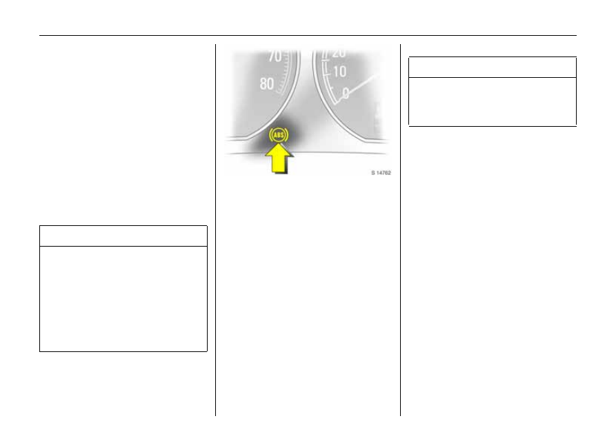
Control ind icator  u for  ABS 

It illum ina tes for  a few  seconds  after the 
ignition is turned on. The  system is read y 

for operation  when the  control indicator 
extinguishes. 
If the control indicator does not go out 
after a few seconds, or if it illuminates 

whilst driving,  there is a  fa ult in the ABS. 
The brake system  remains operational 

without ABS  regulation. 
Self-check 

Each time the ignition is turned on and the 
engine started , after  moving away from  a 

speed  of around 2  mph (3 k m/h)  the system  
performs a self-check  which may be 

audible.

Fault 

You  can continue  driving, provided you 
drive with care and anticipation. 
Hav e the cause of the fault elim ina ted by a 
workshop. The self-d ia gnosis integrated  

into the system  allows  rapid fault 
identification. 

9

 Warning

For optimum b ra king, keep  the brak e 

pedal fully depressed  throughout the 
braking p rocess, despite the fac t that the 

pedal  is pulsating. Do not red uce the 
pressure on the pedal. 
Do  not let this special safety  feature 
tempt you into taking risks when driving. 
Traffic safety can only be achieved  by 
adopting  a responsib le driving  style. 

9

 Warning

If there is a fault in ABS, the wheels may 

be subject to locking due to braking that 
is heavier  tha n  normal. The ad vantages 

of  AB S are no longer opera tional.

-------------------------------------------------------------------------------------------------------------------------------------------------------------

211

Driving and operation

Wheels, tyres 

See page 297 for suitable tyres a nd 

restrictions. 
Tyres fitted in the factory  are a dapted  to 

the c hassis a nd  provide  optimum driving 
comfort and safety. 

Changing  tyre/wheel typ e 
Before c hanging to other  tyres or wheels, 

note the necessa ry changes. 
If tyres of a  different size  than those fitted  

at the factory are used, the electronic 
speedom eter  may require reprogramming 

to  ensure that the correct sp eed is 
displayed. 

Vehicles with tyre pressure m onitoring 
system 3

If you ha ve winter tyres or a ftermarket 
tyres of a different size fitted, sensors for 

the tyre pressure monitoring system can b e 
retro-fitted  by a  workshop upon request. 

Otherwise the  system will not display  tyre 
pressure deviations.
Tyre pressure monitoring  system 3  – 
see page 204. 

9

 Warning

Use of unsuitab le tyres or wheels m ay 
lead to accidents  and  render the vehicle 

unroa dworthy. 

-------------------------------------------------------------------------------------------------------------------------------------------------------------

212

Driving and operation

Fitting new  tyres 
Fit  tyres in pairs or in sets, which is ev en 

better. Ensure  that  tyres on one a xle  are: 
z the same size, 

z the same  design, 
z the same  make, 

z and  have  the same tread  pattern. 

Fit  direc tional  tyres such that they roll  in  the 

direc tion of travel. The  rolling d irection  is 
indicated  by  a symbol (e.g. a n  arrow)  on 

the sidewall. 
Tyres fitted opposing  the rolling  direction 

(e.g. when  a tyre is  chang ed) should  be 
refitted  a s soon as possible. This is the only 

way to obtain full  benefit from the design 
properties of the tyre. 

Some b ra nd s  of  tyres  have a  b eaded  ed ge 
for a lloy wheels  to  protect against 

damage. If  wheel  trim  is  used on steel 
wheels with beaded-edg e tyres, the 

following procedure must be followed: 

z Use wheel trims and tyres tha t are 

approved by  Vauxhall for the vehicle in 

question a nd  therefore meet all the 
requirem ents  pertaining to the 

respective wheel/tyre c om bina tion.

z If the wheel trims and tyres used a re not 

Vauxhall-app rov ed, the tyres must not 
ha ve  a beaded  edg e. 

9

 Warning

Use of unsuitable tyres or wheel trims 
could  lead  to  sudden loss of air and 

thereby accidents. 

-------------------------------------------------------------------------------------------------------------------------------------------------------------

213

Driving and operation

Tyre pr essure 

Check tyre pressures, including  the spare 
wheel, at  least ev ery  14 days  and prior to 

any long journey; the tyres should be 
check ed when cold. Don’t forget to check  

the spare. 
Use the v alve cap key to make unscrewing  

the valve caps easier. The key is located on 
the inside  of  the tank flap. 

In vehicles with tyre p ressure monitoring 

system 3  there is an ad apter in the valve 
cap key.  Screw adapter to valv e before 

attaching tyre pressure gauge - 
see p age 204. 
Tyre p ressure  - see  page 299. 
Do not reduce tyre pressure when the tyres 

are wa rm. Otherwise the pressure may 
drop  b elow the perm issible minimum when 

the tyres cool down. 
After having chec ked  the tyre pressures, 

tig hten the va lv e ca ps  using the v alve  cap 
key. 

Incorrect  tyre p ressures will im pair sa fety, 

vehicle handling, c om fort a nd  fuel 
econom y and w ill  increase tyre wear. 
If the pressure is too  low , this  can result  in 
consid erable tyre warm-up and  interna l 

dam age, lead ing to tread separation and 
even to tyre blow-out at high speeds.
Hidd en tyre dama ge is not elim inated by 
adjusting  the tyre pressure. 

9

 Warning

Incorrect tyre  pressure  could lead to  a flat 
tyre. 

-------------------------------------------------------------------------------------------------------------------------------------------------------------

214

Driving and operation

Tyre cond ition, w heel condition 

Drive over edges slowly and at a rig ht 
angle if p ossible. Driving ov er sha rp  edges 

can lead to hidden tyre damage a nd wheel 
dam age  which is only noticed later  on. 
When pa rk ing, ensure  that the  tyres a re  not 
pressed  against the ed ge of the kerb . 

Check  tyres regularly for dama ge 
(p enetrated foreign bodies, punctures, 

cuts, c ra cks, bulges in side  walls).  Chec k 
wheels for dam age. If dam age  or  unusual 

wear is found, contact a  work shop. 

Tread  d ep th 

Check tread depth regularly. 
If w ear in the  front is greater than that in 

the  rear, m ov e the rear wheels to the front 
axle and vice versa.
Correct tyre pressure. 
For reasons of safety, tyres  should be 

replaced when their tread depth has worn 
down to 2 to 3 mm  (winter tyres: 4 mm). 

9

 Warning

Dama ge m ay lead to tyre blow-out.

-------------------------------------------------------------------------------------------------------------------------------------------------------------

215

Driving and operation

The legally  permissible minimum  tread 

depth  (1.6 m m) has  been reached when 
the tread has worn down as far as one  of 

the w ear indicators (TWI

1)

). A  number of 

wear indicators a re spaced at equal 

intervals around the tyre within the  tread. 
Their position  is indicated by markings on 

the tyre sidewall. 

General information 
z The  danger of aq uap laning  is greater if 

the  tyres are worn. 

z Tyres  age, even  if they a re  used  only  very 

little or not at  all. A spare  wheel which 
has not b een  used  for  six years should  be 

used w ith ca re. 

z Never fit  used tyres the prev ious history 

and use  of w hich you  do not  know. 

z So  as  not to im pair brake cooling , use 

only wheel trims app rov ed for use on 
your vehicle. 

Tyre d esigna tions 
Meaning s: 
e.g. 195/65 R 15 91 H 

Speed code letters: 

1)

TWI

 = 

T

read 

We

ar 

I

ndicato r. 

195 = Tyre  width  in  mm
65

= Cross-section ratio

(tyre height to width) in %

R

= Belt type:  Radial

15

= Wheel d ia meter in inch

91

= Load ind ex e.g. 91 c orresponds 

to 618 kg

H

= Speed cod e letter

Q

up to 100  mph (160 km/h)

S

up to 112  mph (180 km/h)

T

up to 118  mph (190 km/h)

H

up to 130  mph (210 km/h)

V

up to 150  mph (240 km/h)

up to 168  mph (270 km/h)

-------------------------------------------------------------------------------------------------------------------------------------------------------------

216

Driving and operation

Winter tyres  
For notes on fitting new tyres – 

see page 212. 
See page 299 for restric tions. 
Winter tyres im prove safety at 
tem peratures below 7 °C and should 

therefore be fitted on all the wheels. 
The d esign of summ er tyres mea ns they 

have limited  qualities for  winter driving. 

If the m aximum p ermissible speed for the 
winter tyres is less than  that  of the vehicle, 

a notic e indicating the maxim um  
permissib le speed for the  tyres must be 

affixed  within the  driver’s field of vision

1)

If you use the  spare wheel when  it  is  fitted 

with  a sum mer tyre,  the vehic le’s 
driveab ility may b e affected, esp ecially on 

slippery road  surfaces. Obtain a 
replacement for the  faulty tyre  as  soon as 

possible, and have the w heel  balanced 
and fitted to the vehicle. 

Wheel trims  
If the wheel trims and tyres  used  are  not 

Vauxhall-approved, ma ke sure that the 
tyres  do not  have  a beaded  edg e - 

see page 212. 

1)

Varies from  cou ntry to  co untry on accou nt o f 

nation al regulations.

-------------------------------------------------------------------------------------------------------------------------------------------------------------

217

Driving and operation

Tyre cha ins  3 

Restrictions and  further information – 
see page 299. 
Tyre c hains are only permitted on the drive 
wheels  (front axle). They must be  fitted to 

the tyres symmetrica lly in order to achieve 
a concentric  fit. 
Always use fine  mesh chains  that  add no 
more than 10 mm to the tyre tread and the 

inboard sides (including  chain  lock). 

Wheel trim on steel w heels could com e into 
contact with parts of the chain and be 

damaged. R emove the  wheel  trim  – 
see p age 239. 
Tyre chains may only be used a t speeds up 
to 30 m ph (50 km/h)

1)

 and, when travelling 

on roads that are free of snow, they may be 
used  for brief periods only since they are 

subjec t to rapid wear on a hard  road  and 
may snap. 

Temporary wheel 3
Tyre chains  must not be used on the 

temporary spare wheel. If you need  to  use 
tyre chains  after suffering  a flat front  tyre, 

fit the  temporary  spa re on the rear axle 
and transfer one  of  the rea r  wheels to the 

front axle. 
For notes on the tem porary spare wheel – 

see page 237. 
Wheel changing  – see pag e 238. 
Correct tyre pressure. 
Tyre pressure monitoring  system 3  – 

see page 204. 

1)

Varies from  cou ntry to  co untry on accou nt o f 

nation al regulations.

-------------------------------------------------------------------------------------------------------------------------------------------------------------

218

Driving and operation

Roof racks 

3


For  safety reasons  and to avoid  roof 
dam age, we recommend using the 

Vauxhall roof  ra ck system  approved  for 
your vehicle. 
Fasten the roof rack following the 
instructions that ac company the system. 
Driving hints –  see  page 184. 

Version without roof railing 

Fold cov ers of  installation openings 
up wards. 
Attac h  roof rack  at appropriate points - 
see enclosed roof luggage rack system 

instructions. 

Version with roof ra iling  

Attach roof rack to roof railing at p oints 
show n in illustration - see enclosed roof 

luggage rack  system instructions. 

9

 Warning

Disreg ard of these notes ca n lead to 

injuries which may be fatal. Vehicle 
passengers must b e informed 

according ly. 

-------------------------------------------------------------------------------------------------------------------------------------------------------------

219

Driving and operation

Towing equipment 

3


Only use a ca ra van/trailer  tow ing  dev ice 
approved for the  vehicle. Hav e a  tow ing 

device  fitted by workshop, who will inform  
you of any  possible  caravan/trailer load 

increases.  They will hav e the instructions 
for fitting  the device  and any necessa ry 

changes to the vehic le concerning cooling, 
heat  shields or other  devices. 

For installation dimensions of the 

carava n/trailer towing equipment  – 
see pages 311, 312. 

Towing equipment with 

removable coupling ball bar 

3

Saloon / Hatch

3


Stowa ge of coupling b all b ar 
The coupling ball ba r  is stored  in  a bag 

strapped to the  spa re wheel. 

Fitting  the coupling b all b ar

Com press  the sealing plugs at the ends 
and  pull out of the opening  for  the  coupling 

ball  bar. Stow  the sealing plugs in the 
luggage compa rtm ent. Disengage socket 

and fold d ow n  3. 

6

9

 Warning

Disreg ard of these notes ca n lead to 

injuries which may be fatal. Vehicle 
passengers must b e informed 

according ly. 

9

 Warning

The coupling  ball bar  is to b e removed 
when not towing . 

-------------------------------------------------------------------------------------------------------------------------------------------------------------

220

Driving and operation

Checking the  tensioning of the c oupling 

ball b ar:
z Red m arking on turn  knob  points 

towa rd s green m arking  on  coupling ba ll 
bar.

z Gap of approx. 6 millimetres  between 

rotary knob and coupling ball  bar.

z Key is in lock. 

Otherwise, the coupling ball  bar must be 

tensioned  before it is  inserted into the 
coupling housing: 

z Open coupling ball  bar, 
z Pull turn k nob  out  and  then turn  it 

clockwise  as  far as it will go –  
see illustration.

Inserting the  coupling b all bar

Insert the tensioned coupling ball bar in the 
coupling housing and push firmly upwards 

until you hear  the coupling ball ba r 
eng aging. 
The turn knob snaps back  into its home 
position resting a gainst the  coup ling  ball 

bar. 

9

 Warning

Do not  touch the  turn k nob  when 

inserting the coupling  ball bar  – risk  of 
injury. 

-------------------------------------------------------------------------------------------------------------------------------------------------------------

221

Driving and operation

Open coupling ball b ar. Remove key and 

put on provided protectiv e clip.
When the coupling b all bar is locked the 

turn  knob  can no longer b e pulled out. 

Imp or tant 
Check  that  the coupling  ball bar  is correctly 

installed: 
z Red mark ing  on  turn knob p oints 

towards white  marking on coupling  ball 
bar. 

z No gap between turn k nob and coupling 

ball b ar. 

z Coupling ba ll  bar must be seated  firm ly 

in coupling housing. 

z Coupling ba ll  bar must be locked  and 

key  m ust  be  rem oved. 

Eye for b reak-aw ay  stopping c able 
In the case of carava ns/trailers with brake, 

attach the break-away stop ping  cable to 
the eye. Eye - see Fig. 17721 J. 

Dismounting  the coupling b all b ar 

Close coup ling ball bar. 
Pull the turn knob out and then  turn it 

clockw ise as far as it will go.  Pull the 
coupling ball b ar downwards out  of  the 

coupling housing and  stow it in the 
luggage compa rtm ent –  see p age  219, 

Fig. 17729 J. 
Insert the  sealing plug in the  hole for  the 

coupling ball b ar. Fold  away the socket  – 
see page 219,  Fig.  17717 J. 
Do not use steam -jet cleaners or other 
high-pressure clea ners to clean the 

coupling ball b ar. 

9

 Warning

Towing is permitted only with a c orrectly 
fitted  towb ar. If the towbar cannot be 

fitted correctly, contact a workshop. 

-------------------------------------------------------------------------------------------------------------------------------------------------------------

222

Driving and operation

Towing equipment with pivoting 

coupling ball bar 

3


Folding out the c oup ling b all ba r

The release  lever is in the stowage 
compartment to the left in the luggage 

compartment. 
To open  the stowa ge c om partment,  push 

both latches down and  open the  cover. 

Push the release lever down; the LED on the 

lever is  illuminated while  the coupling ball 
bar is not engaged. A wa rning buzzer also 

sounds  and the coupling ba ll  bar pivots 
down. 

Swivel the coupling ba ll  bar back wards 
until it engages (see Fig. 17726 J). The LED 

must  g o  out  a nd  the  warning  buzzer  must 
cease. Otherwise, repeat the proced ure. 

Importa nt 

Check tha t the coupling  ball bar is correctly 
eng aged: 
z LED is not  illuminated. 
z No warning buzzer. 

9

 Warning

Mak e sure that no one is in the p iv ot zone 
of the c oupling b all  bar. Risk of b od ily 

injury. 

-------------------------------------------------------------------------------------------------------------------------------------------------------------

223

Driving and operation

Ca rava n/tra iler with break-a way cable  

For  caravans/trailers with brak es, loop 
break-away cable around  coup ling  ball 

bar. 

Stowing  the coupling ball b ar 

Open the stowage compartment  – 
see p age 222. 
Push the release lever down; the LED on 
the lev er remains  illuminated as long as 

the coupling ball ba r  is  not engaged . 
A warning  buzzer  also sound s a nd  the 

coupling b all bar piv ots down.
Piv ot the coupling ball ba r to the right and 

up . The LED  must g o  out  and  the wa rning 
buzzer m ust cease,  otherwise repeat the 

proc edure. 

Caravan/trailer towing

Carava n and tra iler loads

1)

The permissib le carav an/trailer load s a re 
vehicle-dependent and  engine-dependent 

ma ximum v alues  which  must not be 
exceeded. The actual carava n/trailer load 

is the d ifference  between the actual gross 
weight of  the carav an/trailer  and  the 

actual c oupling socket  load with the 
carav an/trailer atta ched. When the 

carav an/trailer load  is being checked, 
therefore, only the caravan/trailer w heels – 

and not the joc key wheel – m ust be 
standing  on  the weighing  apparatus. 
The permissib le carav an/trailer load s for 
your v ehicle  are giv en in the  vehicle 

documents. Unless otherwise stated, they 
are  valid  for  g ra dients  up   to  max.  12%. 

9

 Warning

Caravan/trailer towing is permissible only 
when the c oupling ba ll bar is engag ed 

correctly. If  the coupling ball b ar cannot 
be engaged correctly, the LED  does not 

go out or the warning b uzz er does not go 
off.  Seek the  assistanc e of a  work shop. 

1)

Observe n atio nal regulations. 

-------------------------------------------------------------------------------------------------------------------------------------------------------------

224

Driving and operation

The permissible cara van/trailer load should 
be fully utilised only by drivers who are 

adequately  experienced in  towing large or 
heav y carav ans/trailers. 
The permitted carav an/trailer load ap plies 
up to the  specified  incline  and up to an 

altitude  of 1000 m etres abov e sea -level. 
Since engine power decreases as altitude 

increases because of the air becom ing  
thinner, therefore reducing  climbing  ability, 

the p ermitted  towing  weig ht a lso 
decreases by 10% for every 1000 m etres of 

additional altitude. The towing weight 
does not have to be reduced when driv ing 

on roads with slight inclines (less than  8%, 
e.g. m otorways). 

The actual carav an/trailer  load  plus  the 
actual gross weight of  the towing vehicle 

must not exceed the maximum permitted 
tow ing  weight. For example, if the 

permitted Gross Vehicle Weight is utilised , 
the caravan/trailer load must only b e used 

until the  maximum  permitted towing 
weight is rea ched.  The maximum 

permitted towing weight  is shown on  the 
identification plate - see p age 282. 

Coup ling socket load 
The  coupling socket load is the load  

exerted by the ca ra van/trailer  on  the 
coupling ball. It can be va ried by changing 

the  weight distribution when loading the 
carav an/trailer. 
The m aximum permissible coupling  socket 
load (Saloon / Hatch:  78 kg, Estate: 85 k g) 

is specified  on the towing equipment 
identification plate and in the  vehicle 

documents.  Alw ays aim for the  maximum 
load,  espec ia lly in the c ase of heav y 

carav ans/tra ilers. The  coupling socket  load 
should never fall below 25 kg. 
When measuring the coupling  socket load , 
ma ke sure that the drawbar  of the loaded  

carav an/trailer  is at  the same  height as it 
will be when  the carav an/trailer is coupled  

with the towing vehic le loa ded. Particularly 
important for carav ans/trailers  with 

tandem axle. 

-------------------------------------------------------------------------------------------------------------------------------------------------------------

225

Driving and operation

Rear axle load  during tow ing 
When the carava n/trailer is coup led up  and 

the towing vehicle is fully load ed, including 
all occupants, the  permissib le rear axle 

load (for inform ation -  see the 
identification plate or vehicle 

documentation) may be exceeded  by 50 
kg. The Gross Vehicle Weight rating must 

not be exceeded in the process. 
On  the increased  payload  version 3, the 

permissible rear axle load may be 
exceeded by  65 kg .
If the  permissib le rear axle load is 
exceeded, a maximum speed  of 60 mp h 

(100 km/h) must  be  applied. If lower 
nationa l  speed  limits  are p rescrib ed for 

vehic les towing  caravans/trailers,  these 
must be  observed . 

Tyre pressure 

Ad just the tyre pressure  on the towing  
vehicle to the v alue specified for a full load 

- see  page 299. Also  check  the pressure of 
the carav an/trailer w heels and the sp are 

wheel. 

Trailer Stability Assist 3 (TS A) 
TSA  monitors vehicle movements when 

towing a  caravan/trailer. If the system 
detects lurching movem ents, engine power 

is reduced while the vehicle a nd  
carav an/trailer  com bination is selectively 

brak ed until the lurching ceases. 
TSA  is a  function of the Electronic Stability 

Programme (ESP

®

Plus

) - see page 196. 

-------------------------------------------------------------------------------------------------------------------------------------------------------------


Content      ..     12      13      14      15     ..