Iran Khodro Bardo. Service Manual - part 2


  Index      Manuals     Iran Khodro Bardo. Service Manual


Search            copyright infringement  


Content      ..      1      2      3      ..


Iran Khodro Bardo. Service Manual - part 2


-------------------------------------------------------------------------------------------------------------------------------------------------------------
22

2

Warning

-No object should be on the vehicle floor (in front of the driver); otherwise it may slip under the pedal in the event of the sharp braking.

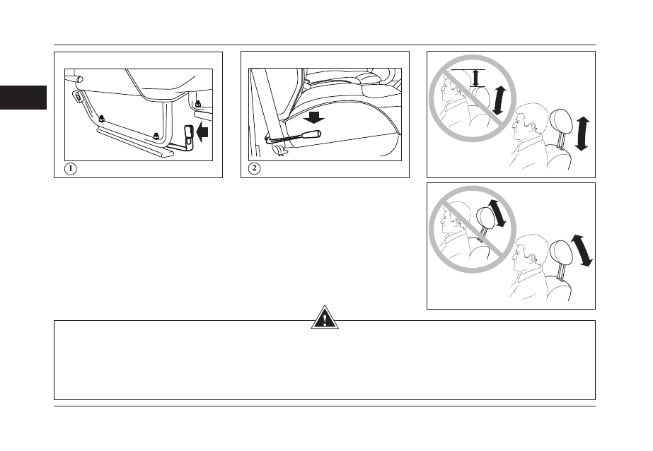
-Head restraints are safety devices. Make sure they are in place and adjusted correctly.

-To minimize the risk of the injury of the driver and front seat passenger, adjustment of the head restraint and position of the head 

aligned with it should be done as shown in the figures.

-Never adjust the Seat while you’re driving. 

Seat


Driver’s seat is equipped with the control 

lever for adjusting the seat regarding 

driver’s height. To adjust the seat (1), pull 

the leaver towards door (driver’s side) 

while seating on the seat. Move the seat 

to the favored position, and then release 

the lever.

Rail seat

This lever is located only on the driver’s 

seat. The point is that both backrest 

seats (driver and passenger) can not be 

adjusted.In the case of passenger seat. To 

remove the spare tire, the backrest seat 

should be fold down.

SEATS

-------------------------------------------------------------------------------------------------------------------------------------------------------------

-------------------------------------------------------------------------------------------------------------------------------------------------------------

23

2

Warning

-Seat belt should be across your shoulder 

to have optimum efficiency. Make sure 

the seat back is positioned correctly.

-make sure no object, especially adhesive 

materials, enter the buckle, otherwise 

buckle may function not properly. 

Caution 

• Never use the seat belt for the children under 6 years old, till it is used with    the child seat. 

• Never use the seat belt for more than one person. 

• The damaged seat belts should be changed. 

• The seat belts anchorages should be checked regularly. 

• You are not allowed to make any changes in seat belt system. 

Seat belts

Wear your seat belt at all times; it is 

mandatory by regulations and important 

for your safety.

Seat belt will keep you safe in case of any 

accident (even a minor one).

Adjust your seat.

Make sure the seat belt is not twisted and 

has no contact with sharp edge parts.

Pull the latch plate attached to the seat 

belt and press it into the buckle unit and 

make sure that:

Upper part of the seat belt is between 

neck and shoulder (figure 1)

Lower part of the seat belt is low across 

the pelvis.

Push the red button to unfasten the seat 

belt (figure 2)    

SAFETY BELTS

Reel or automatic seat belt

To make sure the good performance of 

the seat belt, pull the belt very slowly when 

the vehicle is on a fairly level ground, 

otherwise the belt locks. 

The seat belt is being locked in the 

following situations: 

- The safety belt locks if there’s a sudden 

stop or crash/accident. 

- When driving on very steep hills, or 

winding roads.

-------------------------------------------------------------------------------------------------------------------------------------------------------------

-------------------------------------------------------------------------------------------------------------------------------------------------------------

24

2

Warning

Child should never travel on the lap of 

the passengers.

There is  the risk of sever injuries when 

the child is sitting on your lap.

Never use the same seat belt for more 

than one occupant.

Child safety

Iran Khodro has observed all safety issues 

when manufacturing the vehicle. However, 

you should be very cautious when traveling 

with children. To avoid any possible incident, 

keep following points in your mind:

1- Take care of the child hands when 

closing vehicle doors

2- Never leave children in a vehicle parked 

in the sun, with the windows closed.

3- Never leave children under the age of 

10 alone in the vehicle.

4- Never let children sit between two seats.

Before opening the doors, make sure it is 

safe to open the door.

Special cares for children

Never allow a child to travel on lap of the 

front passenger. 

(Risk of the impact with glove box in case 

of an incident)

Children comfort

Children become irritable during long trips. 

Vehicle environment should be attractive 

for them.

Stop several times to let them have a rest..

Prepare them entertainment which is not 

boring and competitive (book reading, 

listening to the music)

SAFETY CARES

-------------------------------------------------------------------------------------------------------------------------------------------------------------

-------------------------------------------------------------------------------------------------------------------------------------------------------------

25

2

Left lever position (1) 

(a)Maximum Heating 

(b)Minimum Cooling 

By moving the shift lever between (a) and 

(b) positions, you can reach to the desired 

heating/cooling. 

Right lever position (1) 

(c) Turning the Ventilation Off 

(d) Moving Airflow Upward 

(e) Moving Airflow Downward 

Air intake adjustment (2) 

Lever (a):Adjusting Air Supplying 

Lever(b): Controlling and Adjusting the Airflow

HEATING

-------------------------------------------------------------------------------------------------------------------------------------------------------------

-------------------------------------------------------------------------------------------------------------------------------------------------------------

26

2

Bi-fuel vehicles features

Vehicle industry and environment researcher 

have focused on replacing common fuel 

with new fuels which can maintain the 

efficiency  of  the  vehicle  while  having  less 

contamination,  economically  more  efficient 

and easily available.

CNG (Compressed Natural Gas) is a very 

suitable replacement in Iran since we 

have very huge natural gas sources while 

its price is lower. Meanwhile there is vast 

distribution network in the country. 

Iran Khodro Industrial Group after a vast 

study and research  has selected production 

of the bi-fuel vehicles as a work priority  (gas-

gasoline) in line with approaching the world 

market and pioneering in local market.

Your bi-fuel Pick up has been produced to 

achieve above goal.

CNG parts*

Two main sets have been added to make 

your vehicle to run on gas fuel:

A- Kit

B- Cylinder and its accessories

The Kit is a package of various electrical 

and mechanical parts installed in the engine 

compartment. Cylinder and accessories are 

installed in the loading part of the Pick up.

* If equipped

BI-FUEL VEHICLES FEATURES

-------------------------------------------------------------------------------------------------------------------------------------------------------------

-------------------------------------------------------------------------------------------------------------------------------------------------------------

27

2

CNG parts placed in the engine 

compartment*

1- Regulator

2- The hose transferring gas from the 

regulator  to gas adjusting valve

3- Gas flow adjuster

4- The hose transferring gas from adjusting 

valve to mixer

5- Mixer

6- Engine harness (Wires set)

7- Electrical control unit (ECU)

8- Advancer

9- Emulator

10- Gas pressure gauge

11- Manual valve or service valve

12- Warm water shunt hoses to regulator

BI-FUEL VEHICLES FEATURES

-------------------------------------------------------------------------------------------------------------------------------------------------------------

-------------------------------------------------------------------------------------------------------------------------------------------------------------

28

2

1. Regulator:

A valve for regulating the pressure of 

flowing gas to maintain a constant pressure 

(from max.200 bar to 1 bar in three steps) 
2. Gas Pipe (From Regulator to Flow 

Control Valve):

The gas flows from regulator to flow control 

valve through the gas pipe. 
3. Flow Control Valve:

A flow control valve regulates the flow or 

pressure of a fluid to the mixer regarding 

engine condition. 
4.  Gas  Transmission  Pipe  (from  flow 

control valve to mixer)
5. Mixer:

An apparatus used to thoroughly mix outlet 

gases from regulator valve with proper air 

and leads to inlet manifold. 
6. Harness:

 All inlet/outlet signal transmission is done 

through the harness. 
7. Electronic Control Unit (ECU):

A microprocessor and memory with electronic 

maps, forming the central part of an engine 

management system or of subsystems 

such as a fuel injection or ignition system 

and controls engine performances through 

transmission signals to the actuators. 
8. Advancer:

 A mechanism which advances the ignition 

sparks comparing to the gas fuel mode. 
9. Emulator:

By means of a partial resistance, it 

deactivates the petrol injectors so that there 

will be no error on Petrol ECU. 
10. Gas Pressure Gauge: 

It shows the gas pressure inside the tank. 
11. Manual Valve:

A device used to either open or close an 

opening to allow or prevent the flow of a 

liquid or gas from one place to another 
12. Regulator Inlet/Outlet Water Hoses:

To prevent ice while running the engine 

and warm regulator, the hoses lead the 

heater water to the regulator.

BI-FUEL VEHICLES FEATURES

-------------------------------------------------------------------------------------------------------------------------------------------------------------

-------------------------------------------------------------------------------------------------------------------------------------------------------------

29

2

* If equipped

CNG parts in boot* 

1- Gas reservoir:

The compressed natural gas is stored 

under maximum 200 bar pressurized 

2- CNG tank (cylinder) valve:

This device opens or closes the gas valve 

and includes the equipment for safety of 

the system as follows: 

2-1) Pressure Reducer Valve (PRV): A 

valve designed to open and relieve the 

pressure when the pressure exceeds a 

predetermined level. 

2-2) Thermal Safety Valves: If the temperature 

exceeds the set point, it relieves the gas tank. 

2-3) Flow Limiter Valve: If the high pressure 

pipe(HP pipe)is being cut off, it will limit the 

gas outlet from the gas tank. 

3- Transmission Pipe and Gas Conditioning 

System: In the case of any leakage in 

clamps, gas conditioning system will lead 

the gas out of the cabin. 

4- Filler:

Once the filling nozzle is properly clamped 

to the filler neck, the gas starts to flow into 

the vehicle’s tank. 

BI-FUEL VEHICLES FEATURES

-------------------------------------------------------------------------------------------------------------------------------------------------------------

-------------------------------------------------------------------------------------------------------------------------------------------------------------

30

2

Warning

- Any alteration (modification) on the electric circuit should only be done by the one 

of the authorized dealer which have necessary parts available, otherwise only one 

wrong coupling may result to total damage of the electric system (wiring, parts and 

specially the alternator).

Any alteration and/or modification of the fuel feeding systems (electronic control unit, 

wiring, fuel circuit, injector, protection cover,) are strictly forbidden since these may 

cause danger for you. Only experts of the after-sale service network are authorized 

for doing them.

Warning

-Installation of the additional equipments

We strongly recommend you to use only the equipment approved by the manufacturer 

which are compatible with your vehicle and guaranteed, otherwise there may be 

some fault in the proper function of the vehicle and its safety.

-Electric and electronic equipments

Any alteration on the electric circuits of the vehicle should only be done by the one 

of the authorized dealers; otherwise only one wrong coupling may result to total 

damage of the electric system and/or equipment attached to it. Make sure all 

additional installed equipments are protected by fuse. Be aware of the fuse location 

and its max. intensity. 

BI-FUEL VEHICLES FEATURES

-------------------------------------------------------------------------------------------------------------------------------------------------------------

-------------------------------------------------------------------------------------------------------------------------------------------------------------

31

DRIVING

3

CONTROLS.....................................................................32-37

GEAR BOX...........................................................................38

ANTI-LOCK BRAKING SYSTEM (ABS)………………...…..39

IMPORTANT POINTS WHILE USING ANTI LOCK  BRAKING  

SYSTEM ...............................................................................40

SWITCHING ON AND DRIVING WHILE USING CNG .......41- 42

LIGHTS POSITION OF FUEL SELECTION KEY.............43-44

MAIN SWITCH......................................................................45

CNG REFUELING STAGES..................................................46

SAVING FUEL CONSUMPTION......................................47-50

SCREEN WASHER AND SCREEN WIPER..........................51

-------------------------------------------------------------------------------------------------------------------------------------------------------------

-------------------------------------------------------------------------------------------------------------------------------------------------------------

32

3

CONTROLS

16

6

14

5

8

3

15

17

2

7

13

4

12

10

11

9

1

-------------------------------------------------------------------------------------------------------------------------------------------------------------

-------------------------------------------------------------------------------------------------------------------------------------------------------------

33

3

Warning

If the pointer reaches the red mark 

and the warning lamp illuminates, 

stop  immediately  and  seek  qualified 

assistance. 

CONTROLS

Warning lights

1- High coolant tempreature (Red light): 

If the water temperature increases over 

102-105 ◦c, the water warning light comes 

on. In this situation stop the vehicle, do not 

turn the vehicle off. By pouring water on 

the radiator, makes the engine cool rapidly 

(Never leave the radiator cap open). 

2- Low engine oil pressure (Red):

 If the light comes on, turn the engine off 

and fix the malfunction. 

3- Dipped beam & side lamps (Green):

Side lamps come on while the headlamps 

dipped beam turn on. 

4- Diagnostic function: 

The lamp comes on in the case any 

problem with the injection system: 

- Injection system malfunction 

- Ignition system malfunction 

5- Main beam warning lamp (Blue):

 The lights come on while the main beams 

are on. 

6- Battery charge (Red):

The light illuminates as a bulb check when the 

starter switch is turned on and extinguishes 

as soon as the engine is running. If the light 

remains on, or illuminates when driving, 

a fault with the battery charging system is 

indicated. Seek qualifies assistance urgently; 

otherwise the battery may be discharged 

or coolant temperature turned high. This 

indicates either: 

- Faulty operation of the charging circuit 

- Loose battery or starter terminals 

- A broken or slack alternator belt, or 

- A faulty alternator 

7- Low fuel level warning (Yellow):

This indicates that there is less than 7 

liters left in the tank. 

8- Direction indicators (Green):

The corresponding indicator left or right, 

turns on while turning left or right. 

-------------------------------------------------------------------------------------------------------------------------------------------------------------

-------------------------------------------------------------------------------------------------------------------------------------------------------------

34

3

9- Coolant temprature gauge:

The coolant temperature turns warm 

while the engine starts (If the engine is 

cold, the temperature gauge will not move 

till the coolant reaches the acceptable 

degree).The pointer location shows the 

degree of the temperature (left = cold and 

right=warm). When the ignition switch is in 

the “ON” position, this gauge indicates the 

engine coolant temperature. Under normal 

driving conditions, the indicator should stay 

within the normal, acceptable temperature 

range between “H” and “C”- the needle is 

in the central zone. 

Always  remember  that  in  heavy  traffic, 

the pointer goes further to the right. If the 

indicator approaches “H”, overheating is 

indicated which is caused maybe because 

of the gauge malfunction or any other 

probable fault. 

10- Speedometer and odometer:

The speedometer indicates vehicle speed 

in km/h and/or mph.

When the ignition switch is turned to “ON”, 

the display shows the odometer or trip meter. 

The odometer records the total distance the 

vehicle has been driven. The trip meter can 

be used to measure the distance traveled 

on short trips or between 

11- Trip recoreder zero reset:

To reset the distance traveled (zero), press 

the button for 5 seconds. 

12- Tachometer / clock:

The tachometer indicates engine speed in 

revolutions per minute (RPM). 

13- Fuel gauge: This gauge gives an 

approximate indication of the amount of 

fuel in the fuel tank after the ignition switch 

turns to” ON” position. “F” stands for full 

and “E” stands for empty. 

14- Handbrake on:

This indicates the handbrake is not fully 

released. 

15- Open door:

This light remains on until all doors are 

completely closed.

CONTROLS

Warning

Never drive with the engine speed 

indicator in the red zone (over 5500 min.) 

or severe engine damage can result.

16- Anti – Lock Brake System 

Warning (ABS)

It lights up when starting the car and keeps 

on for a few seconds, and then it turns off. If 

it does not turn on when starting the engine 

or stays on after the engine starts running, 

it indicates that there is a problem in the 

anti-lock brake system. In such a condition 

move the car immediately and with safety 

considerations to the authorized workshop 

for inspection and repair.

17-Rear fog lamp

it lights up when using rear fog 

lamps.

-------------------------------------------------------------------------------------------------------------------------------------------------------------

-------------------------------------------------------------------------------------------------------------------------------------------------------------

35

3

Warning lamps

1- Horn:

Press the end of the stalk. 

2-High beam indicator lamp / light:

Pull the stalk towards the steering wheel. 

3- Indicator light: 

Right: Pull the stalk upwards. 

Left: Pull the stalk downwards. 

Overtaking or changing lane:

Move the stalk to the desired direction.

Changing lane compeletely:

To turn right, move the lever all way up. 

The stalk returns automatically to the first 

position, While the wheel is returning.

Turning on the lights: 

4- The lights will get on and off by turning 

of indicator stalk.

5- The dipped beam headlamps get on by 

pulling the stalk towards the steering wheel. 

6- Pull the stalk towards the steering wheel. 

Repeat the step, to turn to dipped beam.

7- Rear fog lamp get on and off by turning 

the indicator stalk.

CONTROLS

-------------------------------------------------------------------------------------------------------------------------------------------------------------

-------------------------------------------------------------------------------------------------------------------------------------------------------------

36

3

Head lamps 

Each head lamp assembly consists of 

one 40 or 45 lamp with two connectors, 

one 5 watt lamp and one reflector (with 

the glass bulb).

Adjusting head lamp main beam (1) 

By turning the screw clockwise or anti-

clockwise direction, you can adjust dipped 

beam or main beam.

CONTROLS

-------------------------------------------------------------------------------------------------------------------------------------------------------------

-------------------------------------------------------------------------------------------------------------------------------------------------------------

37

3

Adjustment

headlamp main beam, direction indicator 

and horn

Headlamps main beam, direction indicator 

and horn are adjusted by the control lever 

located on the left side of the steering 

wheel (see the picture) 

Headlamp main beam:

Headlamps high beam are on in two 

following ways:

(a) Direction Indicator Lever

By pulling the direction indicator towards 

the steering wheel, the headlamp high 

beams are on and then by releasing it the 

headlamps are off. 

(b) Headlamps High Beam Changer 

If the headlamps high beam is on, by pushing 

the steering wheel towards windscreen, the 

headlamps high/low beam changes to other 

position.

Direction indicators 

Turn to the right: Pull the lever up. 

Turn to the left: Push the lever down. 

In the above situations, both the direction 

indicators and green warning lamp flashes 

simultaneously. If the green waning lamp 

does  not  flash  (just  is  on),  it  might  be 

because of the damage on one of the 

side lamps or direction indicator automatic 

system.

Lamps

Rear lamp:

It consist of (1): 

(a) Rear Direction Indicators 

(b & d) Stop Lamps & Rear Lamps 

(e) Reversing Lamps 

CONTROLS

-------------------------------------------------------------------------------------------------------------------------------------------------------------


Content      ..      1      2      3      ..