Snowmobile Ski Doo REV SERIES (2006 year). Manual - part 120
Section 13 WIRING DIAGRAM
Subsection 01 (WIRING DIAGRAMS)
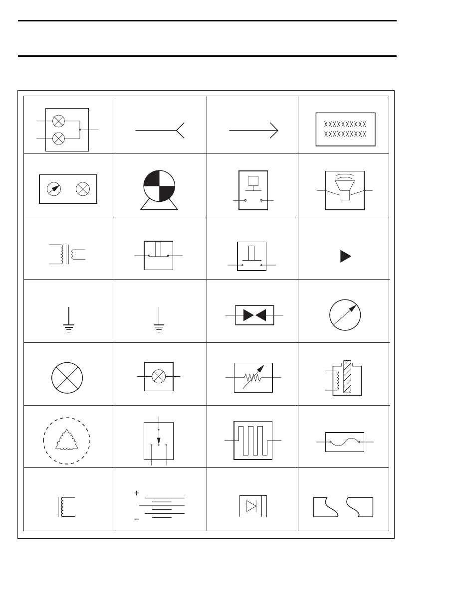
SYMBOLS DESCRIPTION
Beam and tail light
Female terminal
Male terminal
Electronic module
Meter
Electric motor
Low level sensor
Buzzer
Ignition coil
Normally close
switch
Male terminal
on instrument
Engine
ground
Spark plug
Meter movement
Bulb
PilotAnalog sensor
Solenoid valve
Magneto (Delta)
3 position switch
Heating element
Fuse
Normally open
switch
Frame
ground
Frame
Trigger coil
Battery
Diode
Partially illustrated
component
A00E9PS
488
mmr2005-102